

Page 1
pellenc s.a.
Route de Cavaillon
B.P. 47
84122 PERTUIS cedex
(France)
Tel : +33(0)4 90 09 47 00 Fax : +33(0)4 90 09 64 09
E-mail : [email protected]
www.pellenc.com
53_107869_C - 03/2015
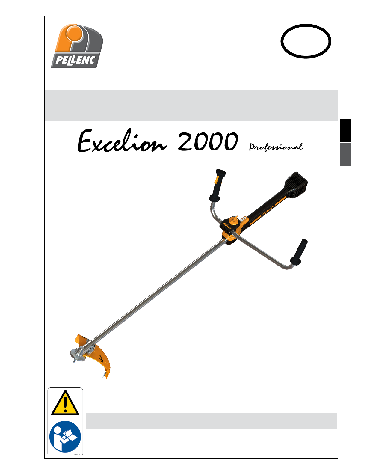
Brush cutter
READ THE USER GUIDE CAREFULLY BEFORE USING THE TOOL
USER GUIDE
Translation of the
original user guide
ENG
CONTENTS:
• Brush cutter with safety parts
• An adjusting key
• A harness
• A user guide
Page 2

Page 3

Table of contents
SAFETY INSTRUCTIONS .....................................................................3
GENERAL SAFETY INSTRUCTIONS FOR THE TOOL ..................................................................4
SAFETY WARNINGS FOR THE EXCELION BRUSH CUTTER AND GRASS TRIMMER ........................................5
SAFETY MEASURES FOR THE CHARGER AND THE BATTERY .........................................................6
SAFETY EQUIPMENT ...........................................................................................7
SAFETY INDICATIONS ..........................................................................................7
DESCRIPTION AND TECHNICAL CHARACTERISTICS .............................................8
TECHNICAL CHARACTERISTICS ..................................................................................9
PREPARING THE MACHINE FOR USE .........................................................10
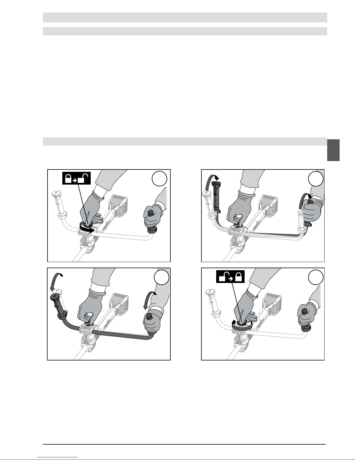
HANDLEBAR ASSEMBLY/DISMANTLING ...........................................................................10
ASSEMBLY/DISASSEMBLY OF THE STANDARD* SAFETY GUARD .....................................................10
ASSEMBLY/DISASSEMBLY OF THE MULCHING SAFETY GUARD ..................................................... 11
ASSEMBLY/DISASSEMBLY OF THE SAFETY GUARD OF THE CHISEL-TOOTH SAW BLADE ................................11
ADJUSTING THE WORKING POSITION ............................................................................12
ADJUSTING THE ORIENTATION OF THE HANDLEBAR ...............................................................12
ATTACH AND ADJUST THE LENGTH OF THE HARNESS, .............................................................13
THE HARNESS
(supplied with the tool)
. . . . . . . . . . . . . . . . . . . . . . . . . . . . . . . . . . . . . . . . . . . . . . . . . . . . . . . . . . . . . . . . . . . . . . . . . . . . . 13
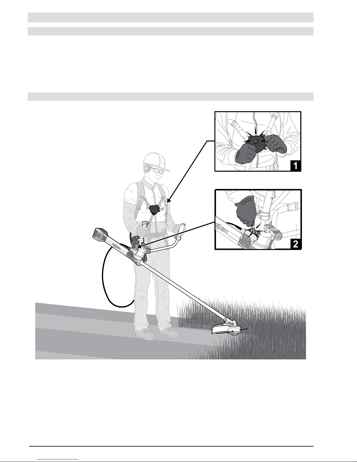
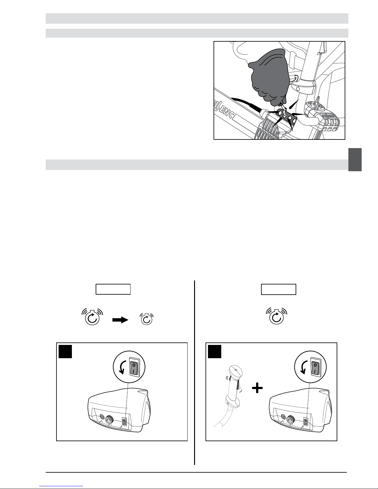
MACHINE BALANCING .........................................................................................14
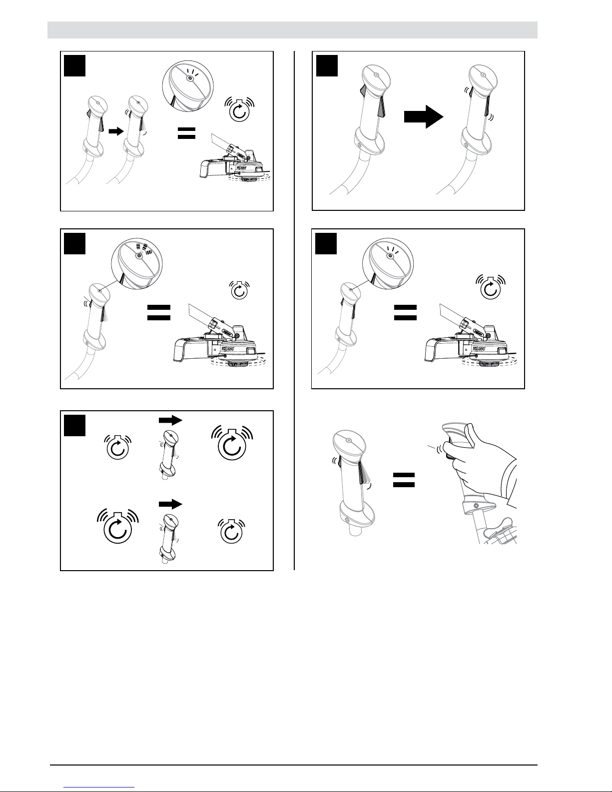
USAGE ...................................................................................14
BATTERY AUTONOMY AND WORKING EFFICIENCY .................................................................16
ROLL CUT CUTTING HEAD ......................................................................................18
TAP CUT CUTTING HEAD .......................................................................................20
MULTI-CUT CUTTING HEAD .....................................................................................22
BLADE CUT CUTTING HEAD ....................................................................................24
CITY CUT CUTTING HEAD ......................................................................................25
THE DIFFERENT WORK TECHNIQUES ............................................................................26
MAINTENANCE ............................................................................28
ANGLE TRANSMISSION LUBRICATION ............................................................................29
SPARE PARTS AND CONSUMABLES REFERENCES .................................................................29
INCIDENTS ................................................................................35
«PELLENC SA» TERMS OF WARRANTY AND NON-RESPONSIBILITY CLAUSE .......................38
‘‘CE’’ STATEMENT OF CONFORMITY ..........................................................40
Page 4

4
All through this user guide you will nd advisory notes and information entitled: REMARK, CAUTION / WARNING.
A REMARK provides additional information, claries a point or explains a step to be followed in detail.
The CAUTION and WARNING advisories are used to dene a procedure which, if neglected or incorrectly performed, may lead to
serious damage to the equipment and/or personal injury.
This advisory:
G
indicates that if the procedures or instructions are not complied with, any damage will not be covered by the
warranty and the owner will be responsible for the repair costs.
Safety indications are also given on the tool; they remind you of the safety precautions to be taken. Identify and read these
indications before using the tool. Immediately replace any indications that may become partially illegible or deteriorated.
Refer to the «SAFETY INDICATIONS» heading in order to identify the location of the safety indications on the tool.
No part of this manual may be reproduced without the written consent of PELLENC. The technical characteristics and the
illustrations given in this manual are for information purposes and are in no way contractual. PELLENC reserves the right to make
any modication or improvement to its products as deemed necessary without informing customers already in possession of a
similar model. This manual forms an integral part of the tool and must accompany the tool if it changes hands.
You must read THE WHOLE of this user guide before using the tool or before carrying out servicing operations.
Comply scrupulously with the instructions and illustrations given in this document.
KEEP THESE INSTRUCTIONS
This manual contains important information and operating instructions for the following tool. Excelion brush
cutter and grass trimmer
KEEP THESE INSTRUCTIONS
This manual contains important information and operating instructions for the following tool.
SAFETY INSTRUCTIONS
Page 5

5
• The Excelion 2000 Professional brush cutter is a professional tool to be used exclusively for cleaning green areas (grass, dense
grass, woody weeds, brambles and small shrubs).
• The PELLENC company declines responsibility in the event of damage caused by incorrect operation or use differing from that
intended.
• The PELLENC company also declines responsibility in the event of damage caused by the use of non-original parts or
accessories.
GENERAL SAFETY INSTRUCTIONS FOR THE TOOL
CAUTION Read all the safety measures and all the instructions.
Retain all the safety measures and instructions for later reading.
Work area safety
a. Keep the work area clean and well lit.
b. Do not use electric tools in an explosive atmosphere, for example in the presence of ammable liquids, gases or dust.
c. Keep children and persons present away when using the tool.
Electrical safety
a. The plugs of the electric tool must be adapted to the base. Never modify the plug in any way whatsoever. Do not use adaptors
with grounded tools.
b. Avoid any body contact with grounded surfaces such as pipes, radiators, cookers and refrigerators.
c. Do not expose tools to rain or damp conditions.
d. Do not misuse the power cord. Never use the power cord to carry, pull or disconnect the tool. Keep the power lead away from
heat, lubricant, sharp edges or moving parts.
e. When using a tool outdoors, use an extension adapted to outdoor use.
f. If you must use a tool in a damp place, use power supply protected by a residual current device (RCD).
Personal safety
a. Remain vigilant, watch what you are doing and use common sense when using the tool. Do not use a tool if you are tired or
under the inuence of drugs, alcohol or medication.
b. Wear safety equipment. Always wear eye protection.
c. Avoid any untimely starting of the device. Make sure the switch is in the off position before connecting the tool to the mains and/
or battery pack, picking it up or carrying it.
d. Remove any adjustment key before starting the tool.
e. Do not rush. Adopt a suitable position and remain balanced at all times.
f. Wear appropriate clothing. Do not wear loose clothing or jewellery.
g. Keep hair, clothing and gloves away from moving parts.
h. If systems are provided to connect dust extraction and recovery equipment, make sure these systems are connected and
properly used.
SAFETY INSTRUCTIONS
This appliance is not intended for use by persons (including children) with reduced physical, sensory or mental
capabilities, or lack of experience and knowledge, unless they have been given supervision or preliminary instructions by
a person responsible for their safety.
KEEP THESE INSTRUCTIONS
Page 6

6
SAFETY INSTRUCTIONS
SAFETY WARNINGS FOR THE EXCELION BRUSH CUTTER AND GRASS TRIMMER
1– Do not use the metal cutting tools near walls, fences, tree trunks, rocks or similar obstacles. Contact with these types of
elements can cause a rebound effect, increase the risk of ricochet and damage the cutting tool. Pellenc recommends using the
CITY CUT for such work conditions.
Clear the work zone of all obstacles (glass, stone, metal, waste, and other solid objects) as they can be projected when working
with the cutting tool.
Never use the Excelion 2000 Professional brush cutter with only one hand.
2– Always use the machine with the cutting head parallel to the ground. The safety guard no longer provides sufcient protection if
the angle of the cutting head is excessive, which is likely to increase the risk of injury.
3– Shut-off the Excelion 2000 Professional brush cutter immediately if the cutting tool starts responding differently (different noise,
increased vibrations). Check that the cutting tool is properly attached and verify its condition (no distortion, sufciently sharp).
Replace any damaged cutting tool as it can explode and cause serious, even fatal injuries.
4– CAUTION: The cutting tool continues rotating for a few seconds after the control trigger has been released.
Always keep your hands and feet clear of the rotating cutting tool.
5– Cutting wire
• Never remove the blade installed in the safety guard as it trims the wire to the appropriate length.
• Never use metal wire or any other material instead of the nylon cutting wire. Metal wire is likely to break and be projected,
causing serious injuries.
• Only use nylon cutting wire recommended by Pellenc with a max. diameter of 3 mm.
6– Cutting blades
Always use an original Pellenc cutting tool.
Tool usage and maintenance
a. Do not force the tool. Use the tool suited for the job.
b. Do not use the tool if the switch does not allow it to be switched on and off.
c. Disconnect the plug from the power source and/or battery pack prior to any adjustment, change of accessories, or before
putting the tool away.
d. When not in use, keep tools out of the reach of children and do not allow persons unfamiliar with the power tool or these
instructions to operate it.
e. Comply with the tool servicing instructions. Check that the moving parts are not out of alignment or jammed, that there are
no broken parts or that there is no other condition which could affect the operation of the tool. If damaged, have the tool
repaired before using it.
f. Keep the cutting components sharp and clean.
g. Use the tool, accessories and blades, etc. in accordance with these instructions, taking into account the working conditions
and the work to be done.
Use of battery-operated tools and usage precautions.
a. Only recharge using the charger specied by the manufacturer.
b. Only use the tools with specically designated battery packs.
c. When a battery pack is not used, store it away from other metal objects such as paper clips, coins, keys, nails, screws or
other small items which can form a connection from one terminal to another.
d. If in bad condition, a liquid may be ejected from the battery; avoid all contact. In the event of accidental contact, clean with
water. If the liquid gets into your eyes, seek medical help.
Maintenance and upkeep
a. Have the tool serviced by a qualied technician, using only identical spare parts.
Page 7
7
53_13_086A
53_13_087A
53_12_050B
53_13_070A
SAFETY MEASURES FOR THE CHARGER AND THE BATTERY
Refer to the Pellenc tools battery manual.
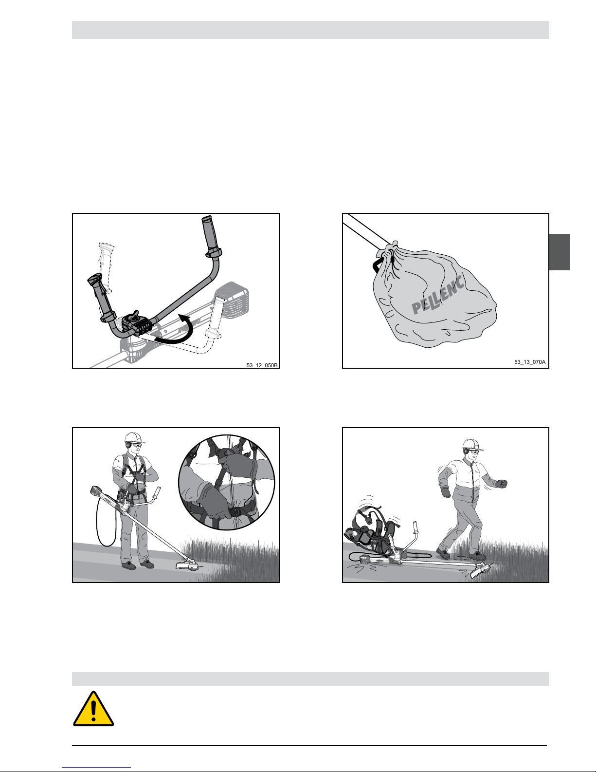
TRANSPORT OF THE EXCELION 2000 PROFESSIONAL BRUSH CUTTER
SAFETY INSTRUCTIONS
1– Keep the original packaging for storing the Excelion 2000 Professional brush cutter in the possible event of shipping the tool for
overhaul or repair.
2– Never carry the machine or the battery by the power cord.
3– Always release the control trigger to stop the electric motor and ensure the cutting tool is no longer moving before putting the
machine on the ground.
4– Place metal cutting tool(s) in their original packaging, or place them in their transport bag.
5– Put the battery back in its original packaging.
6– Turn the handlebar so that it is aligned with the pole to facilitate the transport of several tools.
7– Secure the packed machine and battery in the transport vehicle.
1– A rapid tool release system makes it possible for operators to get away quickly from the tool.
STORAGE OF THE EXCELION 2000 PROFESSIONAL BRUSH CUTTER
1– Keep the original packaging for storing the machine
2– Store the machine in a dry place out of children's reach.
3– Lubricate the output shaft angle during prolonged storage.
EMERGENCY RELEASE OF THE EXCELION 2000 PROFESSIONAL BRUSH CUTTER
Page 8
8
1 5
2 6
3
7
4
8
53_12_006C
1
3
2
4
5
6
7
8
9
10
SAFETY MEASURES
SAFETY EQUIPMENT
SAFETY INSTRUCTIONS
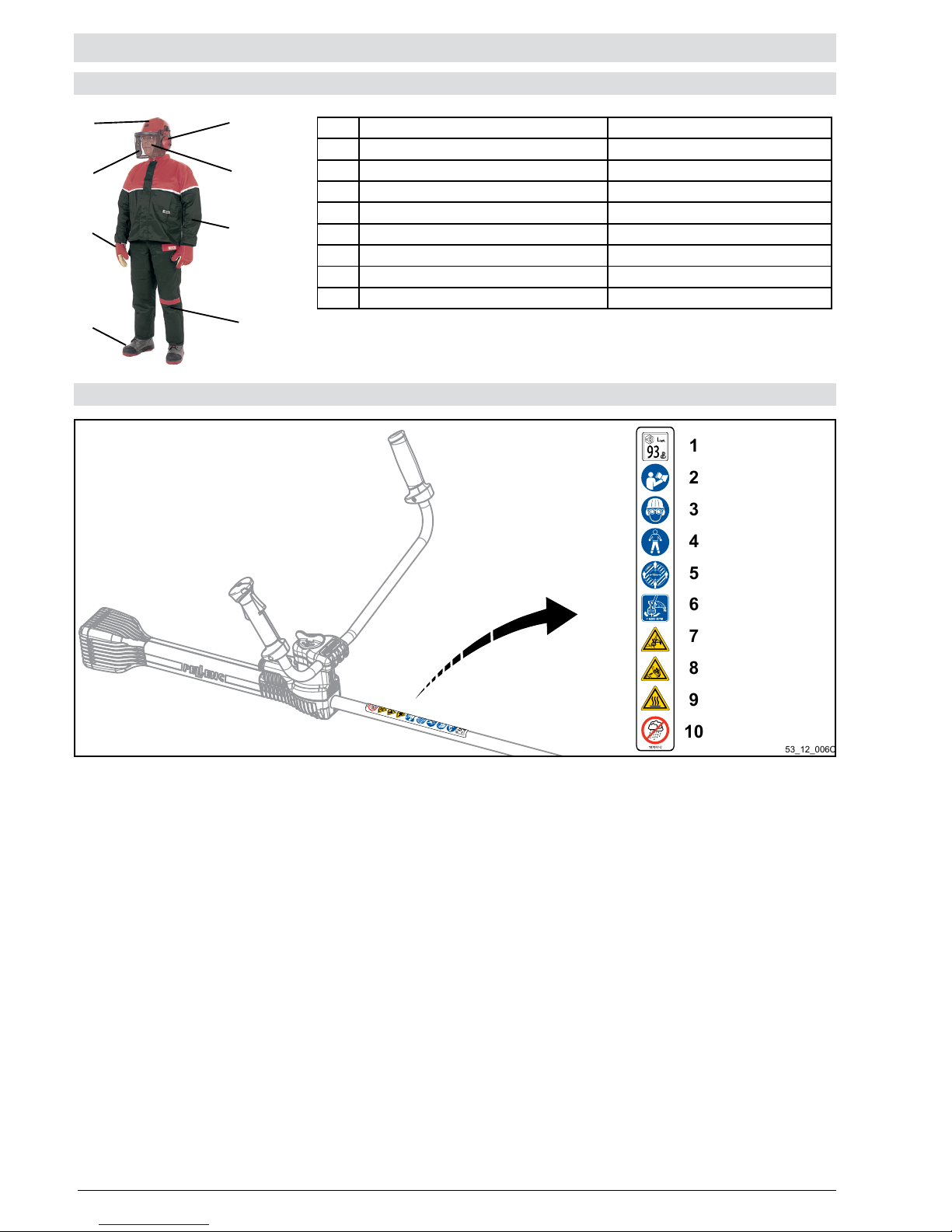
Protective equipment Wearing is
1 Helmet Mandatory
2 Visor Mandatory
3 Hard-wearing gloves Mandatory
4 Safety footwear Mandatory
5 Ear protection Mandatory
6 Safety goggles Mandatory
7 Safety jacket or over-sleeves Recommended/advised
8 Work trousers RMandatory
SAFETY INDICATIONS
1– Noise Levels
Sound power 93 dB
2– Read the user manual
Read the instructions carefully and observe the safety precautions.
3– It is mandatory to wear safety goggles.
Pellenc recommends wearing a protective visor for the face and an approved safety helmet.
4– Gloves, safety pants and safety shoes must be worn
5– Maintaining an adequate safety distance
Be sure to maintain an adequate safety distance of 15 m and ensure that there are no people (especially children) or animal in the
working area of the machine.
Stop the machine immediately if a person or animal approaches.
6– Direction of rotation and maximum speed (6200 rpm)
Pay attention to the direction of rotation of the Excelion 2000 Professional brush cutter. This is indicated on the safety guard.
7– Pay attention to projections
8– Beware of kickback
Avoid all contact between the blade and solid objects.
9– Risk of burns
Do not touch the engine crankcase and the radiator of the electronic motor control board either during or after use of the machine.
10– Do not expose to or work in the rain.
Page 9
9
56_10_016A
53_12_007B
1
2
3
4
5
6
7
8
9
10
11
12
DESCRIPTION AND TECHNICAL CHARACTERISTICS
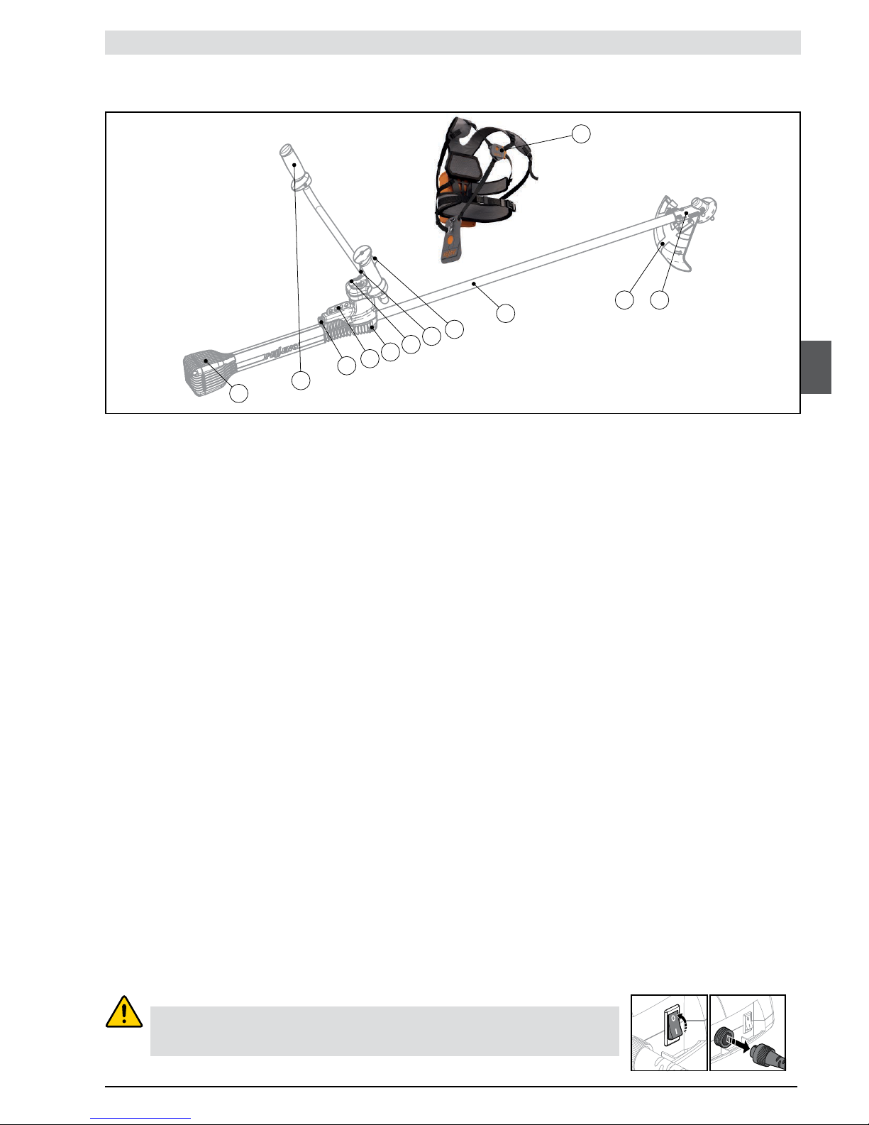
Description of the main elements:
WARNING:
Before working on the tool, check that the On / Off switch is in the off position «0»
and disconnect the battery power lead.
The Excelion 2000 Professional brush cutter is supplied without a cutting head:
They must be ordered independently.
1– Crankcase: Protects the electric motor and allows heat to dissipate.
2– Grip: Used to guide the Excelion 2000 Professional brush cutter
3– Power cord: Connects the machine to the Pellenc power tool battery.
4– Carrying plate: Used to hang the tool using a harness.
5– Electronic control board of the motor and its radiator: Protects the electronic control board and allows heat to dissipate.
6– Handlebar adjustment knob: Used to adjust the angle of the handlebar and put the tool in its transport position.
7– Safety trigger: Prevents inadvertent activation of the control trigger; the safety trigger must be activated prior to activating the
control trigger.
8– Control trigger: Activates the rotation of the cutting tool according to a progressively adjustable speed.
9– Drive tube
10– Safety guard: Limits the risk of the operator being hit by ying objects (stones, bits of metal). A blade attached to the safety
guard makes it possible to obtain the correct length for the cutting wires.
11– Angle transmission
12– Harness
Page 10

10
DESCRIPTION AND TECHNICAL CHARACTERISTICS
TECHNICAL CHARACTERISTICS
Determining the sound levels and vibration rates is based on the operating conditions at the maximum nominal rating.
Maximum A-weighted sound pressure level (ref. 20 µPa) at the position of the user LpA = 84 dB(A) K = 2,5 dB(A)
C-weighted peak sound pressure (ref. 20 µPa) at the position of the user L
pC
< 130 dB(C)
Values dened as per sound measurement standards NF EN ISO 11201 and NF EN ISO 3744.
Symbol Value Unit Reference Comment
L
WAm
92 dB(A) 1 pW Measured sound power level
L
WAg
93 dB(A) 1 pW Guaranteed sound power level
The recording of the measured sound power level and of the guaranteed sound power level has been performed according to a
procedure in accordance with directive 2000/14/CE appendix V.
Excelion 2000
Model Version
Cutting head: ROLL CUT
Power in Watts 2000
Weight (excluding cutting tool and safety guard) in kg 5.4
Dimensions (l x w x h) in mm 1,800 x 450 x 225
Cutting diameter in mm 340
Rotational speed in rpm 2000 to 6200
Battery life Depending on the use and type of battery
Values measured at maximum rated speed
a
h
value
of the
right wrist
measured
in m/s²
a
h
value
of the
left wrist
measured
in m/s²
MultiCut
Ø2.4 wire 1.7 2.1
Ø3 wire 1.7 2
Twin-blade 1.5 1.3
8 teeth 2.4 2
RollCut
Ø2.4 wire 1 1.3
Ø3 wire 1.9 2
TapCut
Ø2.4 wire 3.8 3.2
Ø3 wire 3.5 3.5
BladeCut
Twin-blade 3.5 4.5
Trident 3.5 4.5
Mulching 2.7 2.1
Saw 2.6 2.4
CityCut Blades 1.2 1
Values measured at maximum rated speed in eco
mode
a
h
value
of the
right wrist
measured
in m/s²
a
h
value
of the
left wrist
measured
in m/s²
MultiCut
Ø2.4 wire 1.4 1.3
Ø3 wire 1.5 1.2
Twin-blade 1 0.9
8 teeth 1.9 1.5
RollCut
Ø2.4 wire 1 0.8
Ø3 wire 1.6 1.8
TapCut
Ø2.4 wire 4.4 3.5
Ø3 wire 3.6 2.7
CityCut Blades 1.1 0.8
Vibration emission values according to EN 60745-1, EN ISO 22867:
Measurement uncertainty: K = 1.5 m/s²
Measurement uncertainty: K = 1.5 m/s²
Page 11

11
53_12_012B
53_12_013B
A
B
1
2
3
53_12_008A
53_12_009A
53_12_011B
3
21
1
53_12_010B
2
A
B
C
D
PREPARING THE MACHINE FOR USE
ASSEMBLY/DISASSEMBLY OF THE STANDARD* SAFETY GUARD
HANDLEBAR ASSEMBLY/DISMANTLING
*supplied with the tool
Page 12

12
53_14_023D
53_14_025A
53_14_024B
53_14_026A
A
A
B
B
PREPARING THE MACHINE FOR USE
ASSEMBLY/DISASSEMBLY OF THE MULCHING SAFETY GUARD
ASSEMBLY/DISASSEMBLY OF THE SAFETY GUARD OF THE CHISEL-TOOTH SAW BLADE
Page 13
13
53_12_014B
53_12_017B
53_12_015B
53_12_016B
A
B
C
D
PREPARING THE MACHINE FOR USE
ADJUSTING THE WORKING POSITION
Before using the Excelion 2000 Professional brush cutter, its working position must be adjusted to the operator's size. This makes
it easier for the operator to use and requires little effort.
Adjusting the machine's working position to the operator's size is a 3-step process:
- adjusting the orientation of the handlebar,
- installing and adjusting the harness,
- balancing the machine.
These various adjustments are repeated until the brush cutter is in a suitable working position.
These operations help adjust the position of the handlebar to the shape of the user. Users must not work with their arms stretched
out or completely bent.
ADJUSTING THE ORIENTATION OF THE HANDLEBAR
Take the time to properly adjust your harness and machine. This will guarantee your usage comfort and prevent any
discomfort.
Page 14
14
2
1
PREPARING THE MACHINE FOR USE
THE HARNESS
(supplied with the tool)
Adapting the length of the harness helps adjust the "vertical position" of the Excelion 2000 Professional brush cutter so that it is
within reach and the cutting head is pointing slightly downwards.
(This adjustment is made at the same time as the balance adjustment and the orientation of the handlebar).
ATTACH AND ADJUST THE LENGTH OF THE HARNESS,
Page 15
15
1
6200 rpm
A
53_14_007A
4200 rpm
6200 rpm
53_14_003A
A
PREPARING THE MACHINE FOR USE
1 - Position the harness equipped with its battery.
2- Attach the machine to the harness and make sure it is balanced and well adjusted.
4- Connect the power cord to the machine
5. Power up the tool to select one of the following operating modes:
3- Check that the cutting tool does not touch the ground. Make sure the work area is clear and there is nobody within a 15 metre
radius. Check your safety devices.
MACHINE BALANCING
Put the harness hook on one of the 4 attachment positions
available on the tool.
Use the attachment point which gives you the best tool balance.
USAGE
Mode 1
Mode 2
Page 16
16
53_14_008A
B
53_14_004A
B
6200 rpm
C
53_14_009A
6200 rpm
C
X2
4200 rpm
53_14_005A
X2
D
X2
X2
4200 rpm
4200 rpm
6200 rpm
6200 rpm
53_14_006A
USAGE
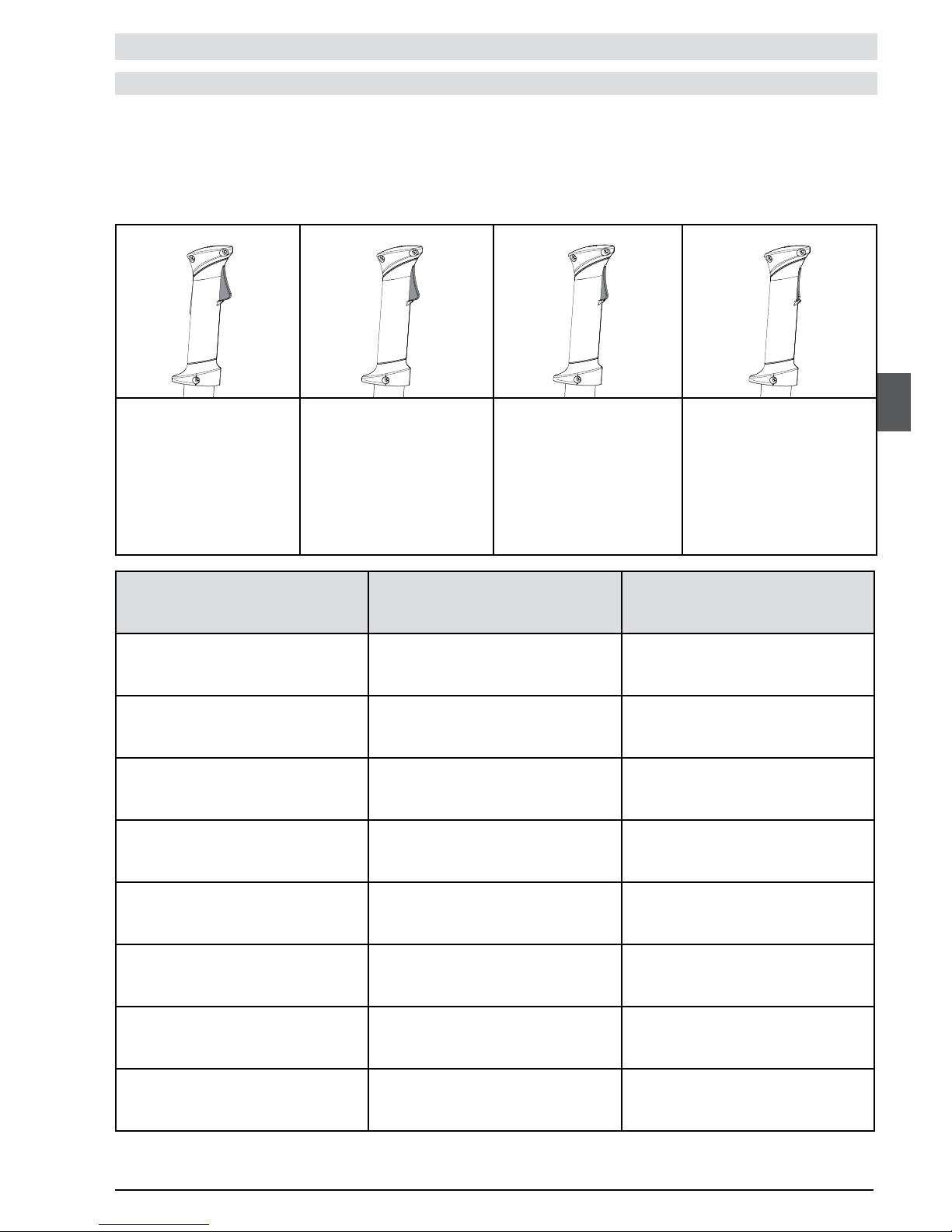
The pressure exerted on the trigger makes it possible to progressively increase the speed to its maximum value.
The tool is now powered up and ready to operate.
Page 17
17
53_12_054A
To optimise the autonomy of your PELLENC battery tool, the rotational speed of the cutting tool used must be adapted to the type
of mowing operation required.
The higher the rotational speed of the cutting tool is, the higher the energy consumption. Therefore the progressive nature of the
control trigger must be used to adjust the rotational speed of the cutting tool.
USAGE
BATTERY AUTONOMY AND WORKING EFFICIENCY
Type of Vegetation or operation Cutting tool recommended Rotational speed recommended
Edges PELLENC wire Ø 2.4 mm 2,000 rpm (eco mode)
Lawn PELLENC wire Ø 2.4 mm 2,000 rpm (eco mode)
Grass PELLENC wire Ø 3 mm 3000 rpm (eco mode)
Dense and tall grass PELLENC wire Ø 3 mm 6200 rpm
Tall and dense scrub brush Twin-blade 3000 rpm (eco mode)
Woody plants 8-toothed blade 3000 rpm (eco mode)
Brambles, plant regrowths, shrubs Mulching blade 6200 rpm
Thinning Chisel-tooth saw 3000 rpm (eco mode)
Minimum speed
Minimum stroke
2000 rpm
Stop
Trigger released
Average speed
50% of the stroke
3000 rpm
Maximum speed
100% of the stroke
6,200 rpm
Page 18

18
53_12_021B
53_12_022C
53_12_023B
53_12_024A
53_12_024A
53_12_024A
53_12_025B
53_13_067A
53_12_027B
53_14_048A
53_13_066A
53_12_029B
+
53_14_049A
53_12_028B
+
53_14_020B
USAGE
Choosing the adequate cutting head is important for the result of your mowing operation, regardless of whether you goal is cleaning and enhancing your green space, or eliminating tall grass and
wild vegetation, or even thickets or bushes obstructing the way.
Pellenc professional offers you a choice of 5 cutting heads:
1- Head: ROLL CUT 2- Head: TAP CUT 3- Head: MULTI-CUT 4- Head: BLADE CUT 5- Head: CITY CUT
For mowing large areas. The
diameter of the wire must be
adapted to the vegetation.
For mowing and clearing edges
Essentially used in cases of signicant
wear and tear of the wire. (along walls
or gratings).
For all types of mowing, requiring a
quick change of tools
Ø 320 mm
Mowing of dense
grass and scrub
brush
Ø 320 mm
Ø 320 mm
Ø 2.4 PELLENC =
lawn
Ø 3 PELLENC =
dense grass and
brush
Ø 240 mm
Grinding of woody
weeds, dense scrub
or thorny vegetation
Ø 2.4 PELLENC
(up to 9 m)=
lawn
Ø 3 PELLENC
(up to 6 m)=
dense grass and
scrub brush
Ø 2.4 PELLENC
(up to 5 m)= lawn
Ø 3 PELLENC (up
to 3.5 m)= dense
grass and scrub
brush
Ø 255 mm
For the mowing of
dense grass and
thick shrub brush
Cutting of shrubs,
plant regrowths
or coppices to be
used with a specic
safety guard
8-tooth blade
Page 19
19
53_13_062A
53_13_056A
53_13_063A
53_13_055B
= 3,5 M
X3
53_12_030C
53_12_031B
53_12_033B
1
2
53_12_032B
A1
A3
A2
A4
B1
B3
B2
B4
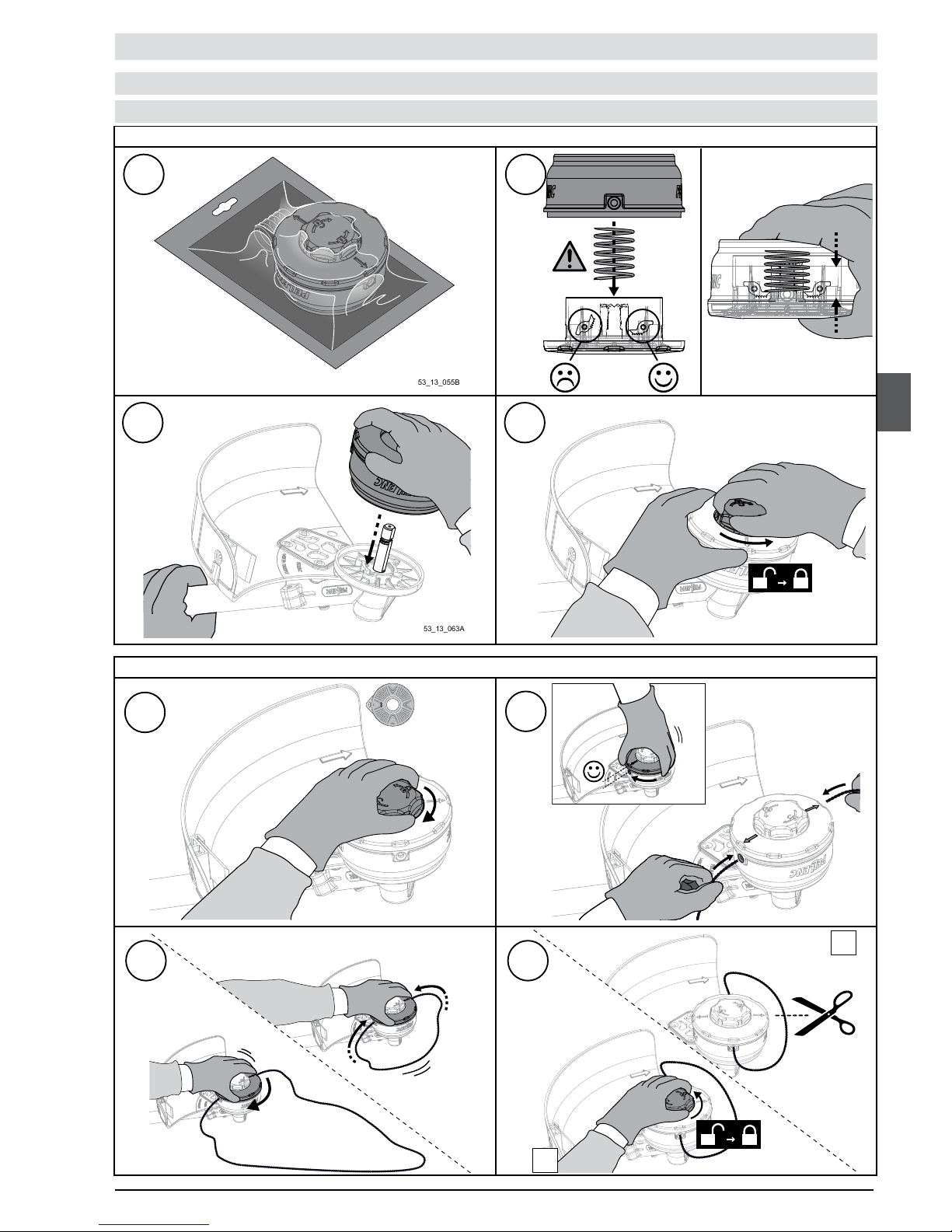
ROLL CUT CUTTING HEAD
USAGE
TECHNICAL DESCRIPTION AND OPERATION
ROLL CUT ASSEMBLY:
CUTTING WIRE ASSEMBLY:
Page 20
20
53_12_034B
x1
53_12_035B
2
1
53_12_037B
53_12_036B
53_13_059B
53_13_057B
53_13_061B
1
2
C1
C3
C2
C4
D1
D3
D2
D4 A2
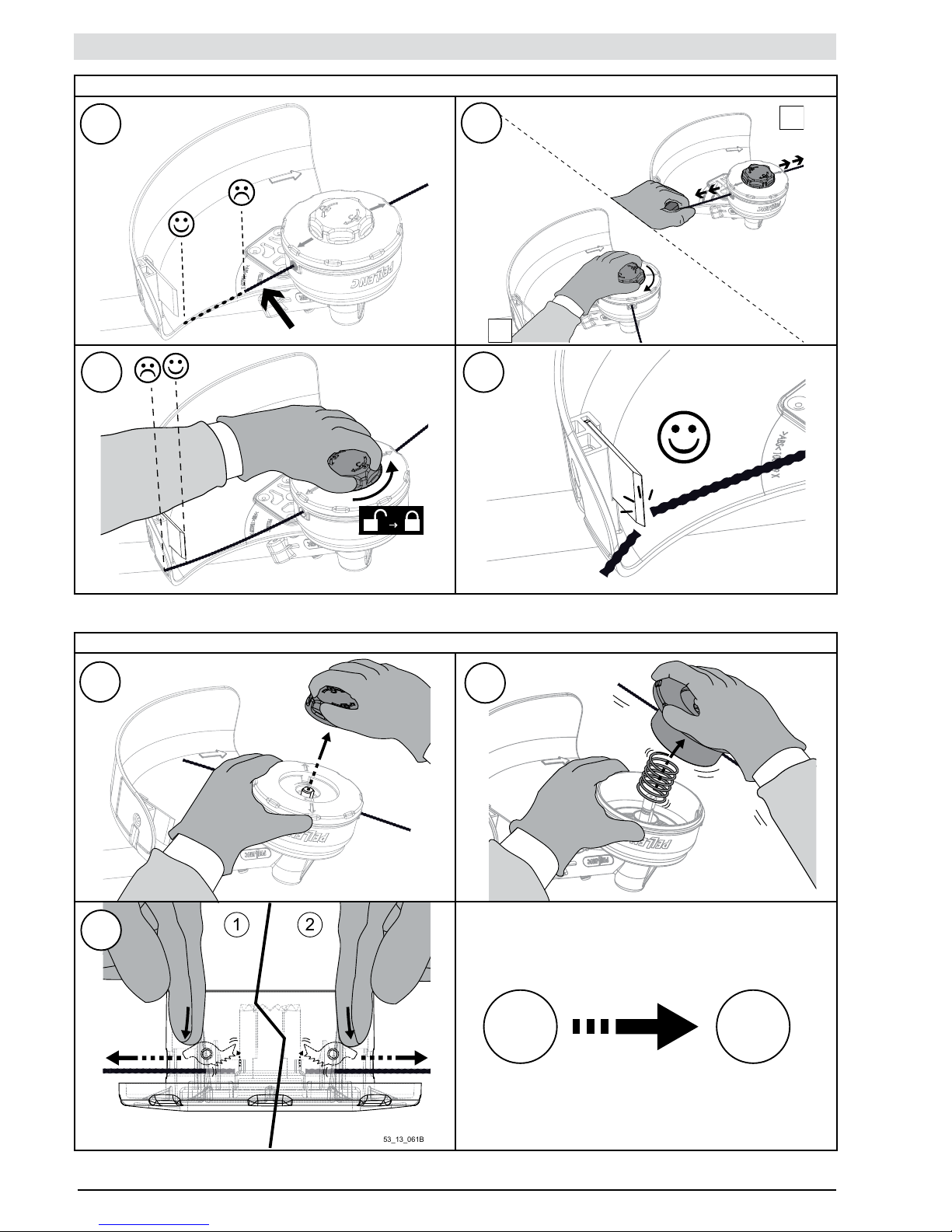
USAGE
ADJUSTMENT OF THE CUTTING WIRE'S POSITION:
ROLL CUT RECHARGING:
Page 21
21
53_13_075A
53_13_076B
= 3,5 M
53_13_078A
53_13_077A
B1
B3
B2
B4
53_13_072A
53_13_074A
53_13_085B
53_13_071A
A1
A3
A2
A4
53_13_073C
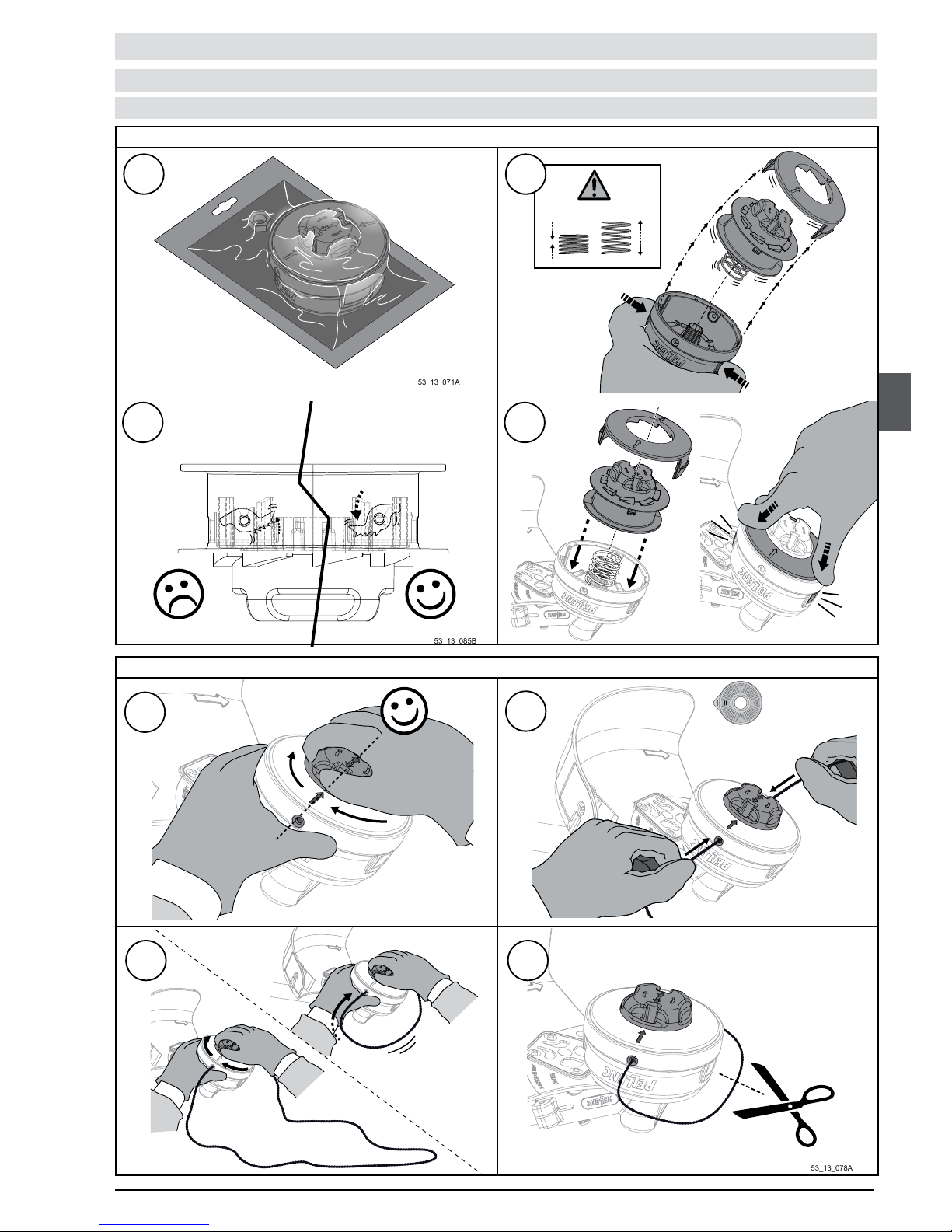
USAGE
TAP CUT CUTTING HEAD
TECHNICAL DESCRIPTION AND OPERATION
TAP CUT ASSEMBLY:
CUTTING WIRE ASSEMBLY:
Page 22
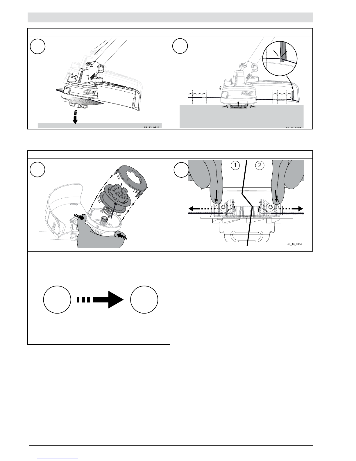
22
C1
C2
53_13_085A
1
2
53_13_083A
D1
D2
D2 A3
USAGE
RECHARGING TAP CUT:
ADJUSTMENT OF THE CUTTING WIRE'S POSITION:
Page 23
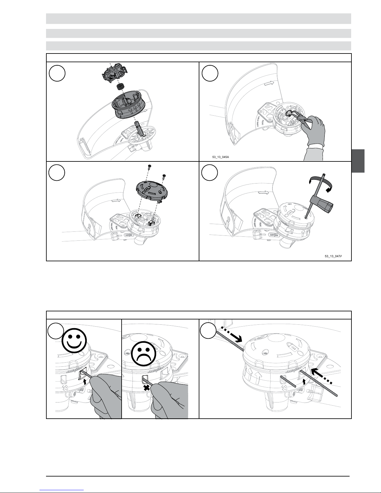
23
53_12_055B
53_13_044A
53_13_046A
53_12_056B
53_13_045A
53_13_047A
A1
A3
A2
A4
B1
B2
USAGE
TECHNICAL DESCRIPTION AND OPERATION
MULTI-CUT CUTTING HEAD
CUTTING WIRE ASSEMBLY:
MULTI-CUT ASSEMBLY:
Page 24
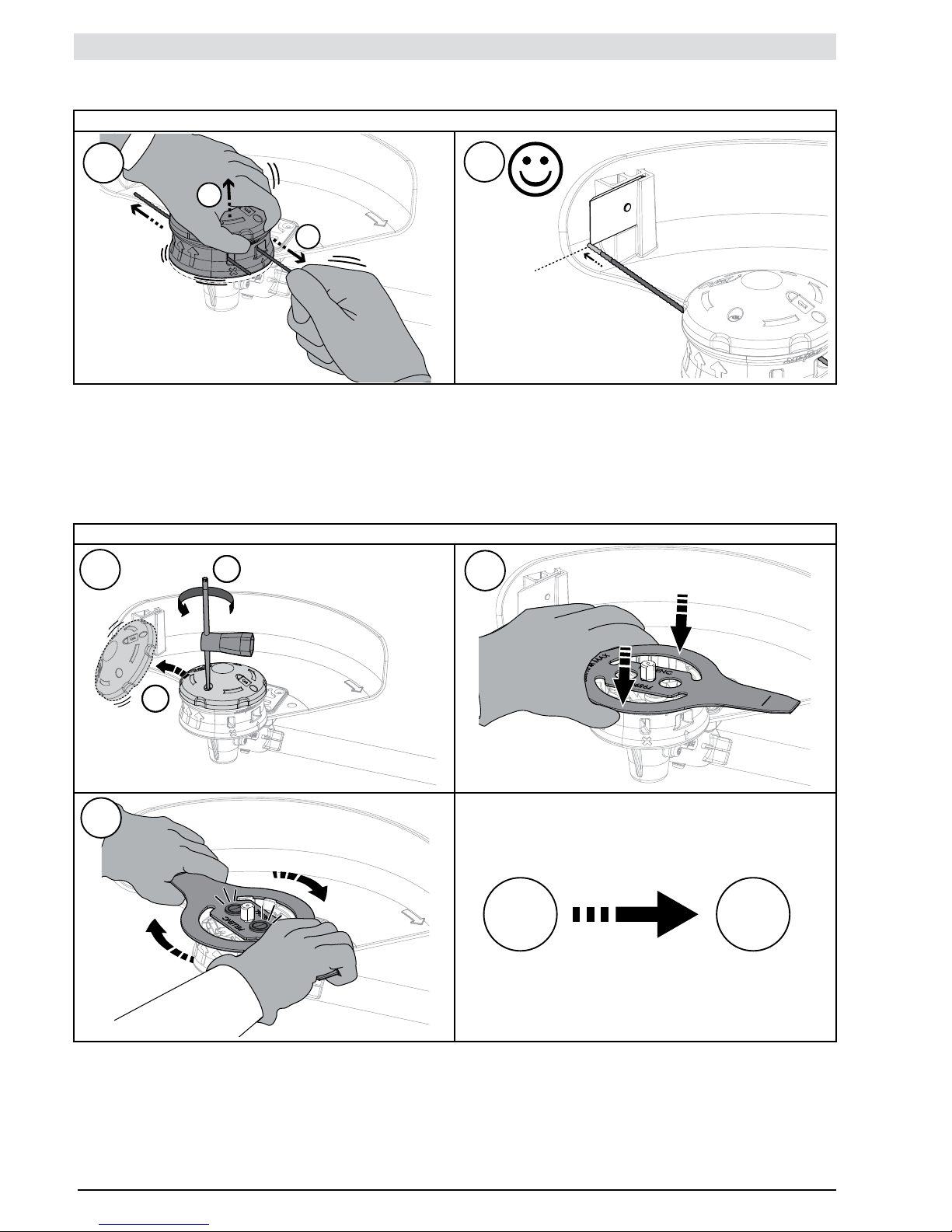
24
53_12_058B
53_12_057B
1
2
121
2
53_12_060B
53_12_061B
C1
C2
D1
D3
D2
D4
A2
USAGE
ADJUSTMENT OF THE CUTTING WIRE'S POSITION:
DOUBLE-TOOTHED BLADE ASSEMBLY
Page 25

25
53_13_089A
53_13_051A
53_13_088A
A1
A3
A5
A2
A4
A6
USAGE
BLADE CUT CUTTING HEAD
CUTTING TOOL ASSEMBLY:
TECHNICAL DESCRIPTION AND OPERATION
Page 26
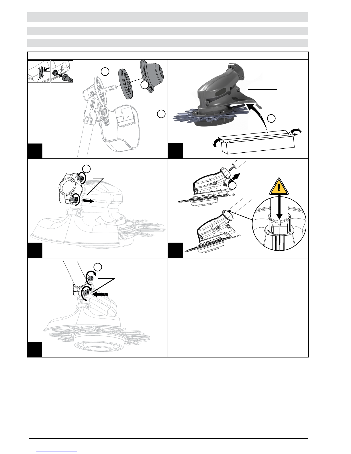
26
53_14_027A
53_14_030A
-360°
x3
53_14_033A
53_14_034A
360°
x3
A4A3
A5
A1
A2
1
2
3
4
57098
5
6
7
USAGE
CITY CUT CUTTING HEAD
CUTTING TOOL ASSEMBLY:
TECHNICAL DESCRIPTION AND OPERATION
Page 27
27
53_12_045A
53_12_046A
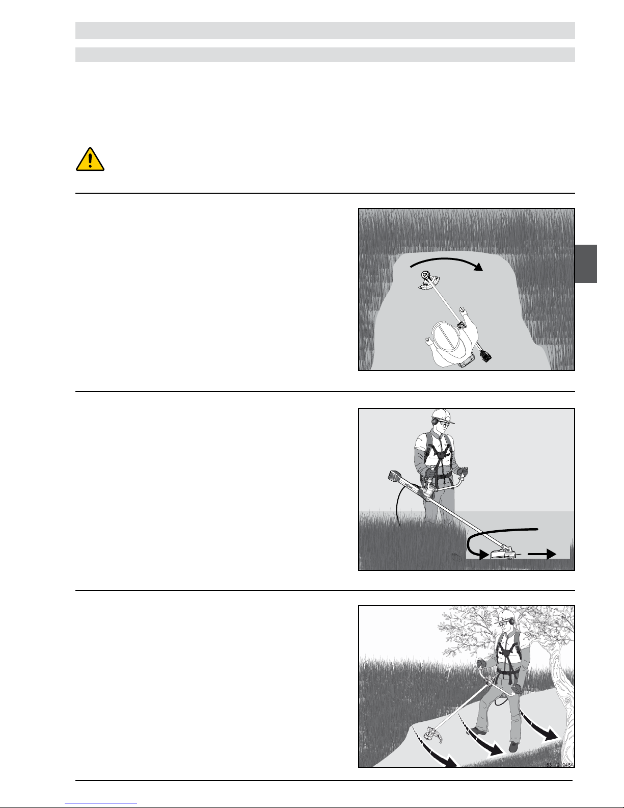
Simply move the tool in semi-circles from left to right while gradually
advancing. Keep the cutting tool parallel to the ground while weeding,
and make sure the cutting head does not touch the ground.
To mow tall and dense grass, start by mowing the upper part, followed
by the lower part of the grass. The mowing movement is from right to
left while left to right is the return movement. Mowing in one direction
only helps with the disposal of cut grass.
THE DIFFERENT WORK TECHNIQUES
Tall grass mowing
Simple mowing
USAGE
Before you start mowing, analyse the surface area to be cleared, the nature of the surface, the slope, the presence of obstacles
etc.
Also pay attention to the wind direction, which can have an impact, to facilitate the disposal of cut grass.
Always follow the slope. Avoid moving up and down the slope. Start at
the bottom, letting cut grass fall downwards, thus avoiding using the
cutting tool on already cut grass.
Work in one direction only, area by area.
Mowing on slopes
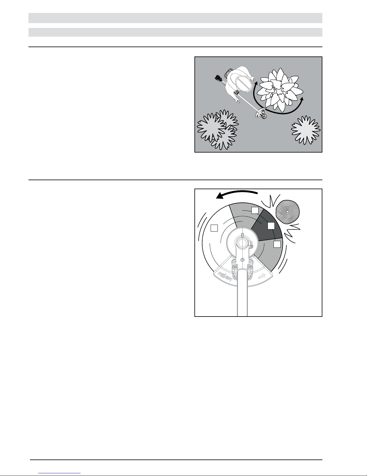
Always keep a minimum distance of 50mm between the cutting head and the obstacle to
avoid any risk of damage to the tool and "wires" (cutting wires).
Page 28
28
53_12_049A
53_13_054A
1
2
3
2
Use the cutting wire as it facilitates grass removal and prevents the
rebound effect when there is contact with a xed obstacle. Protect bark
and the edge of ower beds by using the guard as a shield between
the surface area to be cleared and the vegetation to be protected.
The clearing saw is used for all types of work: thinning, cutting
regrowth, shrubs, woody plants, etc.
Working with the clearing saw is carried out parallel to the ground
observing the direction of rotation of the blade to avoid kickback.
1– high risk of kickback zone
2– high-risk zone
3– work zone
Avoid all contact of the blade with the soil or stones.
THE DIFFERENT WORK TECHNIQUES
Mowing along walls, fences, around trees and ower beds
Working with the clearing saw
USAGE
Page 29

29
MAINTENANCE
REMARK:
Have the machine overhauled every 400 operating hours or once a year at least by an approved Pellenc dealer.
Always store the machine clean and in a dry enclosure with the battery charged.
Every year or as
necessary
X
X
X
X
X
After use
X
X
Monthly
X
X
Every two hours
X
X
X
After starting up
X
X
X
X
X
X
X
Maintenance task
Cleaning the Excelion 2000 Professional brush cutter (no high-pressure cleaner but by
blasting or brushing)
Visual verication of the machine's safety devices (carrying plate, safety guard, angle
transmission)
Verication of the functioning of the trigger safety
Sharpening verication and re-sharpening if necessary
Visual inspection of the cutting tool (absence of cracks or distortion)
Visual inspection of the cutting tool's attachment to the shaft (absence of distortion or
wear and tear)
Verication of the wear and tear of the notched cam teeth and sharpening if necessary or
replacement of the notched cam
Battery level verication
Machine check by an approved Pellenc dealer
Angle transmission lubrication
Page 30
30
1
2
3
4
53_12_038C
53_12_053B
MAINTENANCE
Safety elements:
SPARE PARTS AND CONSUMABLES REFERENCES
ANGLE TRANSMISSION LUBRICATION
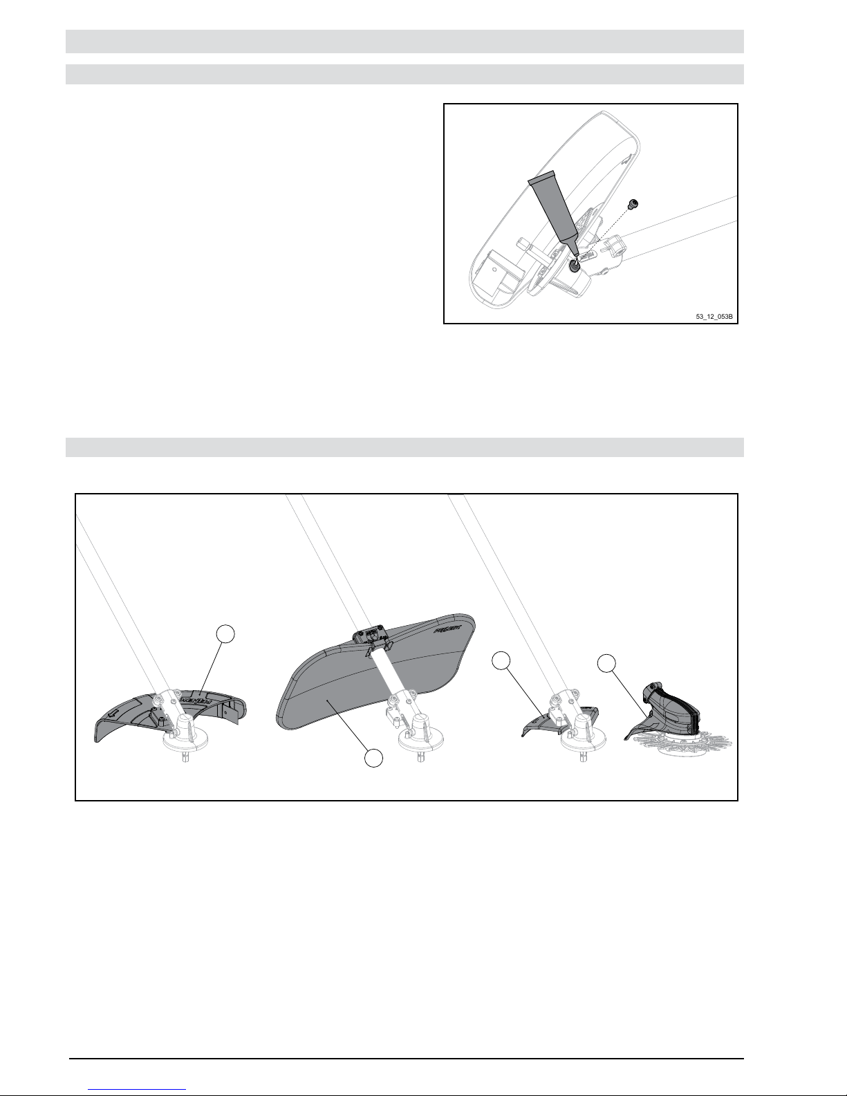
- Grease tube = 35749
- Loosen the screw located on the angle transmission using the
adjusting wrench.
- Open the tube of PELLENC grease
- Apply 4g of PELLENC grease, once a month or every 100 hours.
- Grease the threads of the shaft of the angle to facilitate the release
of the cutting head nuts.
1– Standard housing, ref. 107533
2– Grinding chamber, ref. 111600
3– Chisel-tooth saw housing, ref. 111500
4– CityCut housing, ref. 118267
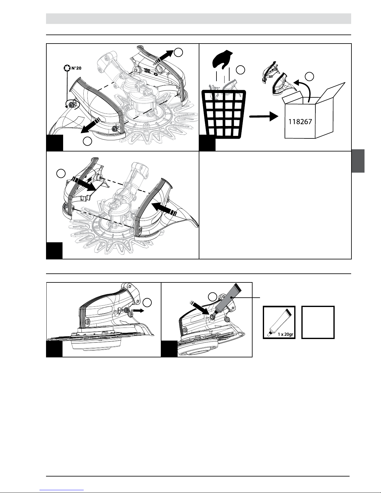
- For specic lubrication of the angle transmission of the CITY CUT
cutting head, refer to the heading "Greasing" on p. 37.
Page 31
31
35749
53_14_050A
53_14_029A
53_14_040A
C1
C3
C2
1
3
4
2
1
53_14_032A
53_14_039A
D1 D2
1
2
x50h
Changing the housing
Greasing
MAINTENANCE
Page 32

32
3
4
5
6
E5
E4
E2
E1
E3
53_14_035A
53_14_036A
53_14_037A
53_14_038A
E6
53_14_045A
2
1
N° 13
53_14_051A
Changing the blade kit
MAINTENANCE
Page 33
33
45°
3.7 mm
53_14_046A
1
2 3
4
5
6
7
8
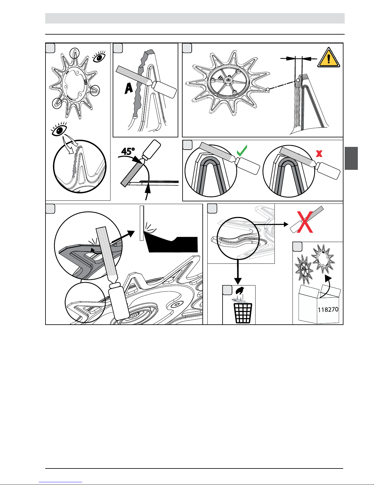
Sharpening the blades
MAINTENANCE
Page 34
34
53_12_039B
2
1
3
4
5
53_12_042B
1
2
3
53_12_040B
1
2
3
4
5
6
1
2
3
4
5
6
53_14_047A
53_12_041B
1
2
3
4
5
6
1– Réf. 118267
2– Réf. 118268
3– Réf. 118270
4– Réf. 118269
5– Réf. 118271
6– Réf. 57098
MAINTENANCE
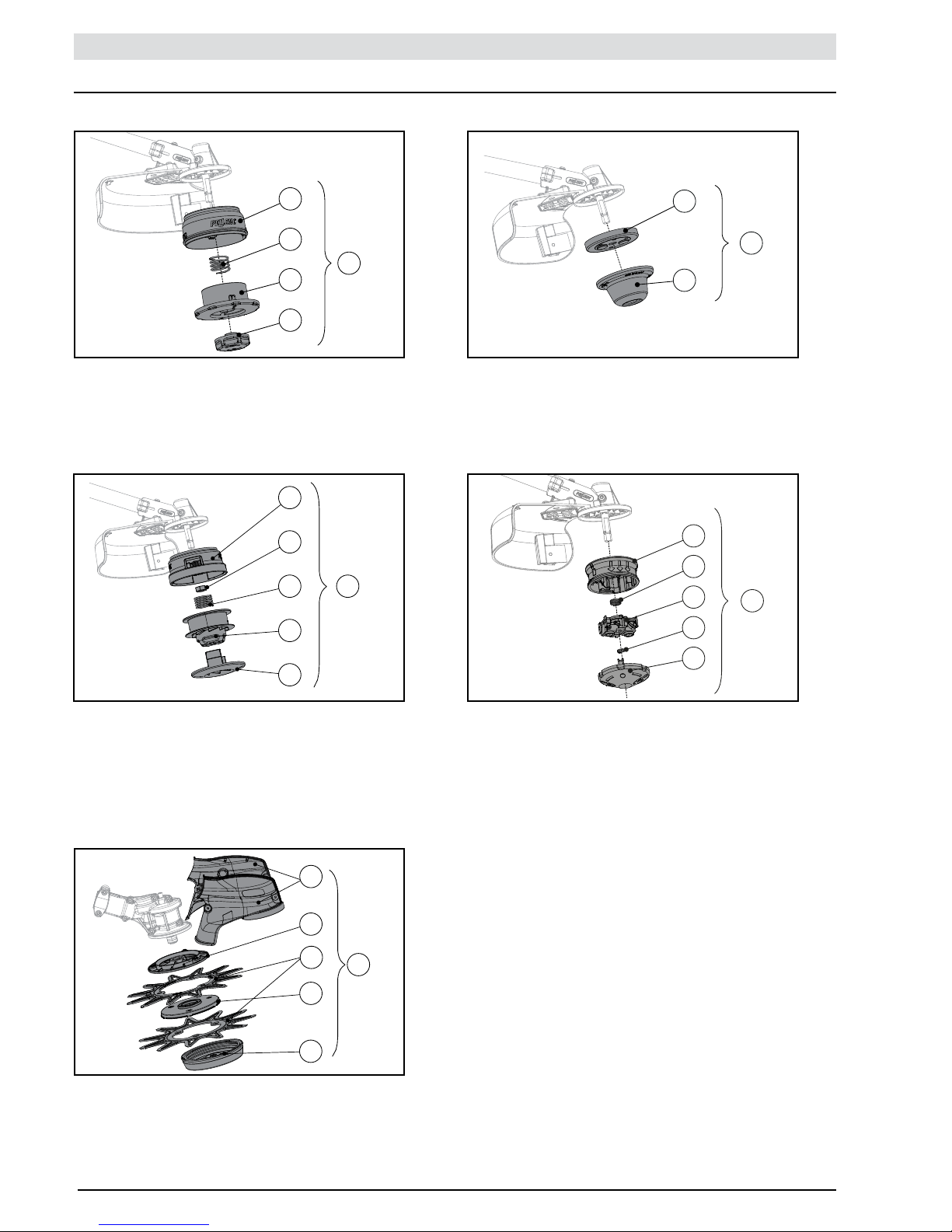
Cutting head parts:
CUTTING HEAD: BLADE CUTCUTTING HEAD: ROLL CUT
CUTTING HEAD: MULTI-CUTCUTTING HEAD: TAP CUT
CUTTING HEAD: CITY CUT
1– Ref. 107711
2– Ref. 107715
3– Ref. 107712
4– Ref. 106803
5– Ref. 57076
1– Ref. 107700
2– Ref. 106645
3– Ref. 57080
1– Ref. 80366
2– Ref. 79032
3– Ref. 80362
4– Ref. 76715
5– Ref. 81116
6– Ref. 57075
1– Ref. 113412
2– Ref. 113414
3– Ref. 107375
4– Ref. 113413
5– Ref. 107374
6– Ref. 57078
Page 35

35
53_12_043D
11
22
33
44
55
77
88
66
+
+
11
22
53_13_068A
MAINTENANCE
Cutting tools:
Accessories:
Consumable:
- PELLENC grease tube = 35749
1– Harness = 110283
2– Carrying bag = 111800
1– Nylon wire shell
Ø 2,4 mm (70 m with ±1%) = 79601
Ø 3 mm (56 m with ±1%) = 108911
2– Nylon wire tube Ø 2.4 mm (200 mm strands) = 79602
3– Bi-blade
Ø 255 mm = 79600 (only on MULTI-CUT)
Ø 320 mm = 110279 (only on BLADE CUT)
4– Tri-blade
Ø 320 mm = 114700
5– Mulching blade = 110281 (only on BLADE CUT)
With recommended mulching safety guard = 111600
6– Clearing saw = 111700
With mandatory housing = 111500
7– 8 tooth blade = 85176 (only for MULTI-CUT)
8– 11- and 12-tooth blades = 118270 (only CITY CUT )
Page 36

36
INCIDENTS
Repaired by
User
PELLENC
approved dealer
User
PELLENC
approved dealer
PELLENC
approved dealer
PELLENC
approved dealer
Solutions
Switch on the battery
switch
Change the cord
Recharge the battery
Change the electronic
board if the diodes remain
off after starting and
checking the previous
points
Change the trigger or
sensor
Change the electronics
board
Checks
Battery switch
Check the cord’s condition
Check that the battery is
not completey discharged
At PELLENC approved
dealer premises
At PELLENC approved
dealer premises
At PELLENC approved
dealer premises
Probable cause
Battery off
The power cord is
sectioned
Battery
Electronic board
A trigger no longer
functions
Electronic board
Condition of
diodes
Off
Off
On
Battery start/stop
switch position
0
I
Symptoms
The tool does not
start
Page 37

37
Repaired by
User
User
PELLENC
approved dealer
PELLENC
approved dealer
PELLENC
approved dealer
User
PELLENC
approved dealer
Solutions
Change the cutting blade
Change the crown
Change the metal blade
retaining element
Change the motor shaft
Change the blocking
device
Checks
Check the blade’s
condition (no cracks or
deformations)
Check there are no
deformations
Check there are no
deformations
Check the shaft’s condition
(no deformations)
Clean the cams
Check the condition of the
teeth
Probable cause
Damaged cutting blade
Damaged crown
Damaged cutting blade
retaining element
Damaged motor shaft
Fouled cutting head
Worn notched cam teeth
Condition of
diodes
On
On
Condition of battery
start/stop switch
I
I
Symptoms
The cutting head
(wire or metal blade)
makes an abnormal
noise or vibrates
heavily
Cutting wire ejected
during use
INCIDENTS
Page 38

38
INCIDENTS
Repaired by
PELLENC
approved dealer
PELLENC
approved dealer
User
User
Solutions
Change the trigger or
sensor
Change the cord
Allow tool to cool for
approximately 5 minutes
Recharge the battery (if
less than 10%)
Checks
At PELLENC approved
dealer premises
Check the condition of the
cord
4 beeps on the battery
When stopped, check
the battery charge level
indicated on the side
display
Probable cause
A trigger no longer
functions
The power cord is
sectioned
The tool has reached its
temperature limit
The battery is discharged
Condition of
diodes
On
Off
Condition of battery
start/stop switch
I
Symptoms
The tool stops during
use
Page 39

39
«PELLENC SA» TERMS OF WARRANTY AND NON-RESPONSIBILITY CLAUSE
MACHINE RANGE FOR OEP
In the event of failure of a mechanical part and subject to normal, rational use and maintenance in compliance with the
maintenance manual, PELLENC sa guarantees its products for a period of ONE YEAR as of delivery; this time shall not
exceed a period of 18 months following departure from the factory of the equipment under warranty : on one hand in accordance
with the conditions stipulated in the warranties of PELLENC sa and on the other hand subject to the delivery report indicating the
commissioning date was made known to PELLENC sa.
In the event of an accident and total or partial destruction of the product, PELLENC sa’s warranty can only be granted, and their
responsibility engaged, if the party claiming the warranty can provide technical proof specifying the origin of the accident, a defect
in materials or a structural defect and the product components which are the cause of it.
This contractual warranty excludes any other responsibility of PELLENC sa, whether implicit or explicit. For this reason, the
responsibility of PELLENC sa can not exceed the limits dened above and covers, to a limited extent, repair or replacement, as
chosen by PELLENC sa, of parts recognized to be defective and, when applicable, the labour required to perform the repair or
replacement on the basis of warranty time as dened by PELLENC sa.
Any maintenance or repair work whatsoever carried out during the warranty period shall mandatorily be performed by PELLENC sa
or by a PELLENC sa authorized dealer, under penalty of forfeiture of the warranty.
All costs arising from the immobilization, movement, approach and transport shall be, in all events, for the sole account of the
purchaser.
As concerns parts or equipment that are not manufactured by PELLENC sa, in particular ball screw, battery, etc., the warranty is
limited to that of the suppliers to PELLENC sa. Normal wear parts worn out as the result of use are never under warranty.
PELLENC sa and the authorized dealer shall not be liable in the following cases:
• Malfunctions due to faulty servicing, user inexperience or abnormal use.
• Failure to perform overhauls and checks in accordance with manufacturer’s instructions.
• Replacement of genuine parts or accessories with parts of accessories of another origin, or when the machine sold has been
transformed or modied.
This warranty is explicitly limited to the terms dened above. PELLENC sa shall not be liable, under any circumstances, for
payment of any indemnity for any reason whatsoever.
However, it is specied, in compliance with the provisions of decree No. 78.464 dated March 24th 1938, that this contractual
guarantee does not replace the legal guarantee which obliges the seller to guarantee the buyer against the consequences of
defects or hidden defects of the object sold.
Page 40

40
• Technical characteristics are given for information purposes only; under no circumstances are they contractual.
• PELLENC reserves the right to make design and and manufacturing modications with the aim of constant progress towards
PERFECTION.
Roger PELLENC
Chief Executive Ofcer
PATENTED EQUIPMENT
NEVER ATTEMPT TO OPEN THE GRASS CUTTING BRUSH-CUTTER OR BATTERY AS YOU RISK INVALIDATING THE
WARRANTY. REFER THE PROBLEM TO AN APPROVED REPAIRER.
Page 41
41
‘‘CE’’ STATEMENT OF CONFORMITY
(ONLY CONCERNS EUROPE)
MANUFACTURER PELLENC S.A.
ADDRESS QUARTIER NOTRE-DAME
ROUTE DE CAVAILLON - B.P. 47
84122 PERTUIS CEDEX (FRANCE)
PERSON/ENTITY AUTHORISED TO COMPILE THE TECHNICAL
DOSSIER
PELLENC S.A.
ADDRESS QUARTIER NOTRE-DAME
ROUTE DE CAVAILLON - B.P. 47
84122 PERTUIS CEDEX (FRANCE)
WE HEREBY DECLARE THAT, FOR THE MACHINE HEREINAFTER REFERRED TO AS:
- GENERIC DENOMINATION BRUSH CUTTER
- FUNCTION MAINTENANCE OF GREEN SPACES
- COMMERCIAL NAME EXCELION 2000
- TYPE EXCELION 2000
- MODEL EXCELION 2000
- SERIAL No.
53P00001 - 53P49999
53P50000 - 53P99999
COMPLIES WITH THE PERTINENT PROVISIONS OF THE MACHINES DIRECTIVE (2006/42/CE)
AND COMPLIES WITH THE PROVISIONS OF THE FOLLOWING OTHER EUROPEAN DIRECTIVES:
- ELECTROMAGNETIC COMPATIBILITY 2004/108/CE
Sound Level at the maximum operating rating
THE FOLLOWING HARMONIZED EUROPEAN STANDARDS WERE USED:
- EN 60745-1
- EN 11806
CONCLUDED AT PERTUIS, DATED 01/12/2014
ROGER PELLENC
CHIEF EXECUTIVE OFFICER
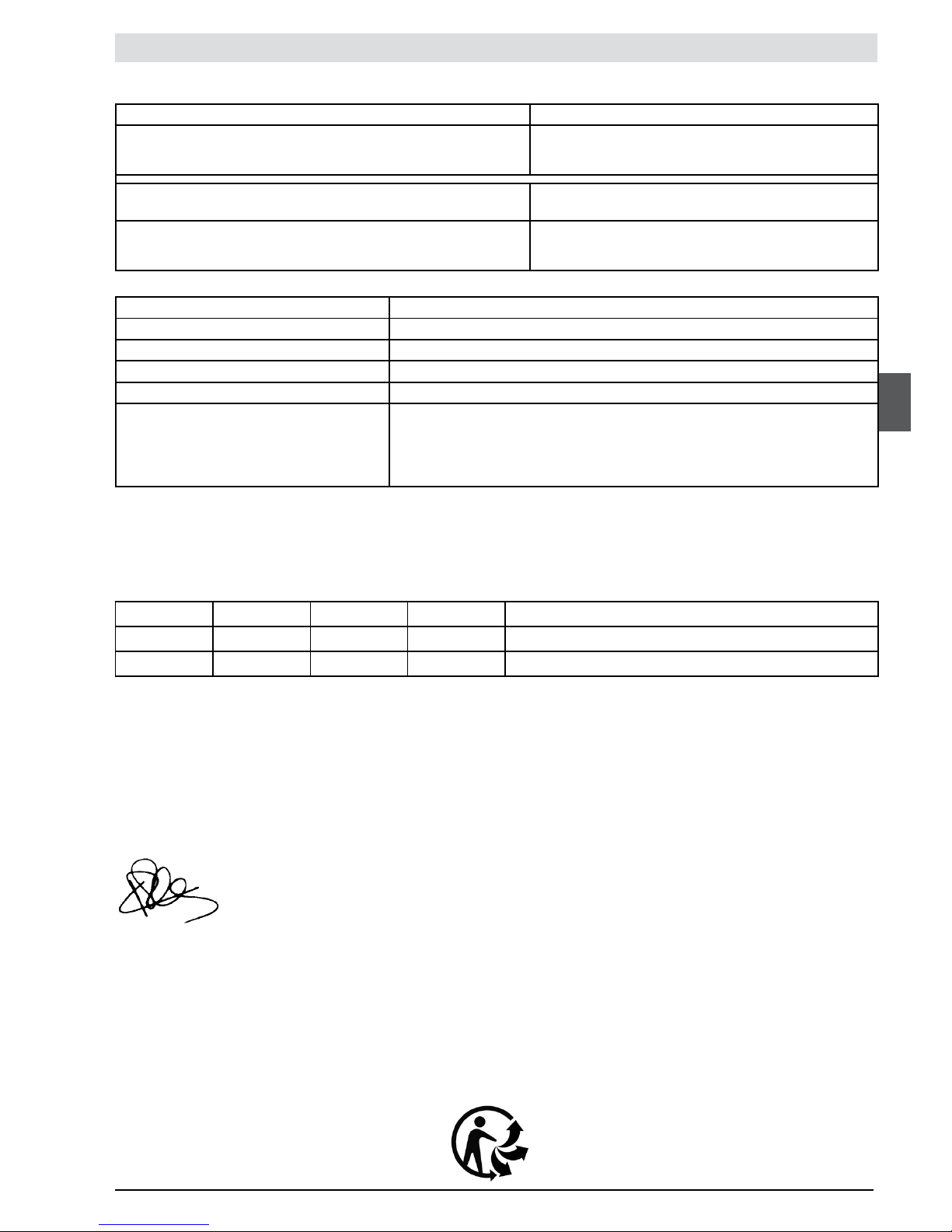
Symbol Value Unit Reference Comment
L
WAm
92 dB(A) 1 pW Measured sound power level
L
WAg
93 dB(A) 1 pW Guaranteed sound power level
The recording of the measured sound power level and of the guaranteed sound power level has been performed according to a
procedure in accordance with directive 2000/14/CE appendix V.
Page 42

 Loading...