

Page 1

USER GUIDE
ENGAIRION 3
Translation of the original
user guide
57_147010_A
06/2018
READ THE USER’S GUIDE CAREFULLY BEFORE USE
Contents:
A blower
A standard outlet blowing nozzle with diameter of 75mm
An Allen wrench
A user guide
Hanging hook (x2)
Quartier Notre-Dame
84120 Pertuis (FRANCE)
Tél : +33 (0)4 90 09 47 00
Fax : +33 (0)4 90 09 64 09
www.pellenc.com
Page 2

Page 3

USER GUIDE AIRIon 3 BLoWER
57_147010_A
TABLE OF CONTENTS
INTRODUCTION 5
SAFETY INSTRUCTIONS 6
GENERAL SAFETY INSTRUCTIONS FOR THE TOOL .................................................6
WORK AREA SAFETY ..................................................................................... 6
ELECTRICAL SAFETY ..................................................................................... 6
PERSONAL SAFETY ...................................................................................... 6
USE AND CARE OF THE POWER TOOL ....................................................................... 7
SAFETY INSTRUCTIONS FOR AIRION ...........................................................8
SAFETY INDICATIONS .......................................................................9
DESCRIPTION AND TECHNICAL CHARACTERISTICS 10
DESCRIPTION ........................................................................... 10
TECHNICAL CHARACTERISTICS .............................................................11
PUTTING THE TOOL INTO SERVICE 12
ASSEMBLY / DISASSEMBLY OF THE OUTLET BLOWING NOZZLE. . . . . . . . . . . . . . . . . . . . . . . . . . . . . . . . . . . . 12
ASSEMBLY ...........................................................................................12
REMOVAL ............................................................................................ 12
ADDING/REMOVING THE NOZZLE PLATE ..................................................... 13
ASSEMBLY ...........................................................................................13
REMOVAL ............................................................................................ 13
ASSEMBLY / DISASSEMBLY OF THE ERGONOMIC ELBOWED NOZZLE (OPTIONAL] ..................... 14
ASSEMBLY ...........................................................................................14
REMOVAL ............................................................................................ 14
ASSEMBLY / DISASSEMBLY OF THE BLOWER SCRAPER (OPTIONAL) ............................... 15
ASSEMBLY ...........................................................................................15
REMOVAL ............................................................................................ 16
CONNECTING THE EXTENSION .............................................................17
START-UP AND OPERATION 18
HOLDING THE TOOL ...................................................................... 18
PREPARING THE BATTERY FOR USE ......................................................... 18
STARTING .............................................................................. 18
SPEED SELECTOR ........................................................................ 19
"BOOSTER" MODE ....................................................................... 20
‘BATTERY LIFE READING’ MODE ............................................................ 20
CARRYING (OPTIONAL) ................................................................... 21
AFTER USE ............................................................................. 22
33333
Page 4

USER GUIDE AIRIon 3 BLoWER
57_147010_A
SERVICING 23
CLEANING .............................................................................23
SERVICING INTERVALS ................................................................... 23
INSTRUCTIONS FOR REPAIRING ............................................................ 23
SPARE PARTS ........................................................................... 24
PART NUMBERS FOR SPARE PARTS .......................................................................24
STORAGE .............................................................................. 24
INCIDENTS 25
PELLENC S.A. WARRANTY AND AFTER SALES SERVICE 27
"EC" DECLARATION OF CONFORMITY 28
444
4
Page 5

USER GUIDE AIRIon 3 BLoWER
57_147010_A
■ INTRODUCTION
ENVIRONMENTAL PROTECTION
Your equipment comprises numerous materials which can be valorised or recycled. Entrust these to
your reseller or to an approved service centre so that they can be processed.
Comply with the regulations in force in your country as concerns environmental protection associated
with your activity.
PLEASE KEEP THESE INSTRUCTIONS
This manual contains important information and operating instructions for the following tool:
AIRION.
It is IMPERATIVE that you read through the ENTIRE USER'S MANUAL before using or servicing the tool.
Always comply with the instructions and illustrations in the manual.
All through this user guide you will nd advisory notes and information entitled: REMARK, CAUTION / WARNING.
A REMARK provides additional information, claries a point or explains a step to be followed in detail.
The CAUTION and WARNING advisories are used to dene a procedure which, if neglected or incorrectly performed,
may lead to serious damage to the equipment and/or personal injury.
This advisory: G indicates that if the procedures or instructions are not complied with, any damage will not be covered
by the warranty and the owner will be responsible for the repair costs.
Safety indications are also given on the tool; they remind you of the safety precautions to be taken. Identify and read
these indications before using the tool. Immediately replace any indications that may become partially illegible or
deteriorated.
Refer to the «SAFETY INDICATIONS» heading in order to identify the location of the safety indications on
the tool.
No part of this manual may be reproduced without the written consent of PELLENC. The illustrations given in this manual
are for information purposes and are in no way contractual. PELLENC reserves the right to make any modication
or improvement to its products as deemed necessary without informing customers already in possession of a similar
model. This manual forms an integral part of the tool and must accompany the tool if it changes hands.
555
5
Page 6

USER GUIDE AIRIon 3 BLoWER
57_147010_A
■ SAFETY INSTRUCTIONS
ʚ GENERAL SAFETY INSTRUCTIONS FOR THE TOOL
This device is not intended for use by individuals (including children) with reduced physical,
sensory or mental capabilities, nor by anyone lacking in experience or knowledge, except if they
are supervised or have received prior instructions from a person responsible for their safety.
• The PELLENC company accepts no responsibility for any damage caused by improper or unspecied use different
from its original intention.
• The PELLENC company accepts no responsibility for any damage caused by the use of non-original parts or
accessories.
WORK AREA SAFETY
Keep the work area clean and well lit. Cluttered or dark areas invite accidents.
Do not operate power tools in an explosive atmosphere, for example in the presence of ammable
liquids, gases, or dust. Power tools create sparks, which can ignite dust or fumes.
Keep children and bystanders away while operating the power tool. Distractions can cause you to lose
control of the tool.
ELECTRICAL SAFETY
The power tool connector must be adapted to the socket. Never modify the connector in any way
whatsoever. Do not use adapter plugs with earthed (grounded) power tools. Unmodied plugs and
suitable sockets reduce the risk of electric shock.
Avoid contact with earthed surfaces such as pipes, radiators, cookers, and refrigerators. There is an
increased risk of electric shock if your body is in direct contact with the ground.
Do not expose power tools to rain or damp conditions. The entry of water into a power tool increases the
risk of electric shock.
Do not mishandle the power cord. Never use the cord for carrying, pulling or unplugging the power tool.
Keep cord away from heat, oil, sharp edges, and moving parts. Damaged or entangled cords increase the
risk of electric shock.
Use an extension cord suitable for outdoor use when operating power tools outdoors. Use a cord
suitable for outdoor to reduce the risk of electric shock.
Use a power supply protected by a residual current device (RCD) when the power
tool is operated in a damp location. Use of a RCD reduces the risk of electric shock.
NOTE: The term “Residual Current Device” (RCD) can be replaced by “Ground Fault Circuit Interrupter” (GFCI)
or “Earth Leakage Circuit Breaker” (ELCB).
PERSONAL SAFETY
Stay alert, watch what you are doing, and use common sense when operating the power tool. Do not
use a power tool when you are tired or under the inuence of drugs, alcohol, or medication. A moment
of inattention when using a power tool can result in serious personal injury.
Use personal protective equipment. Always wear eye protection. Safety equipment such as dust masks,
non-slip safety shoes, helmets, or ear protection used at the appropriate times reduces injuries.
Avoid accidental starting of the tool. Make sure the switch is in the off position before you connect the
tool to the power source and/or battery pack, pick it up, or carry it. Carrying a power tool with your nger
on the switch or connecting a power tool with the switch in the ‘on’ position can cause accidents.
Remove any adjusting wrench before switching the electric tool on. A wrench left attached to a rotating
part can cause injury.
666
6
Page 7

USER GUIDE AIRIon 3 BLoWER
57_147010_A
■ SAFETY INSTRUCTIONS
Do not rush. Keep proper footing and balance at all times. This provides better control of the power tool
in unexpected situations.
Dress appropriately. Do not wear loose clothing or jewellery. Keep hair and clothing away from moving
parts. Loose clothing, jewellery or long hair can get caught in moving parts.
If devices are provided for connecting dust extraction and collection equipment, ensure that these are
connected and properly used. Use dust collectors to reduce the risk caused by dust.
Be vigilant and do not neglect the safety principles of the tool under the pretext that you are used to
using it. A split second of inattention can lead to serious injury.
USE AND CARE OF THE POWER TOOL
Do not force the power tool. Use the power tool suited for the job. The adapted power tool does the work
better and more safely at the speed it was built to operate at.
Do not use the power tool if the switch does not allow it to be switched on and off. Power tools that
cannot be controlled by a switch are dangerous and must be repaired.
Unplug the tool from the socket or remove the battery (if possible) before any adjustment, change of
accessory or storage. These preventive safety measures reduce the risk of accidentally starting the power
tool.
When not in use, keep power tools out of the reach of children and do not allow persons unfamiliar
with the power tool or these instructions to operate it. Power tools are dangerous when operated by
inexperienced users.
Maintenance of the power tool and its accessories is mandatory. Check that the moving parts are not
out of alignment or jammed, that there are no broken parts or that there is no other condition which
could affect the operation of the power tool. If damaged, repair the power tool before using it. Many
accidents are due to poorly maintained power tools.
Keep the cutting elements sharp and clean. Properly maintained cutting tools with sharp cutting elements
are less likely to jam and are easier to control.
Use the power tool, accessories, blades, etc. in accordance with these instructions, taking into account
the working conditions and the work to be done. Using the power tool for operations other than those
specied can result in hazardous situations.
Keep the handles and gripping surfaces must dry, clean and free of oil and grease. Slippery handles and
gripping surfaces make it impossible to safely handle and control the tool in unexpected situations.
777
7
Page 8

USER GUIDE AIRIon 3 BLoWER
57_147010_A
■ SAFETY INSTRUCTIONS
ʚ SAFETY INSTRUCTIONS FOR AIRION
Do not misuse the power lead. Never use the power lead to carry, pull or disconnect the tool. Keep the
power lead away from heat, lubricant, sharp edges and moving parts.
Never modify the connector in any way whatsoever.
Wear safety equipment. Always wear eye protection.
The dust raised during operation can be harmful to health. In case of liberation of dust, wear a dust
mask.
Comply with the tool servicing instructions. Check that the moving parts are not misaligned or jammed,
that there are no broken parts or that there is no other condition which could affect the operation of the
tool. If there is damage, have the tool repaired before using it.
Inspect the work area prior to starting. Remove all debris and hard object such as stones, glass, wires,
etc. which could y and cause serious injuries or damage when the blower is in use.
Use the blower to blow out grass, straw or leaf waste, urban garbage.
Never blow towards people or animals - the blower can lift up small objects and throw them out at high
speed - risk of injury.
While using the blower, be careful not to endanger small animals.
Stop the blower, turn off the battery, disconnect the power cord and wait for the rotor to stop before
opening the air intake grille: risk of serious injuries (moving part).
Do not obstruct, part or all of the air intake.
Ensure air intake grille maintenance.
Inspect the blower before each use, check that the parts are not worn, loose, damaged or missing. Do
not use the blower if it is not in perfect condition.
To avoid re spreading, do not use the blower near wood res or barbecues, etc.
Do not draw up solids or liquids through the intake duct - risk of damaging rotating components and
intake grille.
88888
Page 9

■ SAFETY INSTRUCTIONS
ʚ SAFETY INDICATIONS
USER GUIDE AIRIon 3 BLoWER
57_147010_A
4
5
6
1
Protective equipment Wearing is
1 Visor Optional
2 Gloves Recommended
3 Non-slip safety boots Optional
2
4 Ear protection Recommended
5 Safety goggles Mandatory
6 Protective trousers Recommended
3
57_11_010A
LwA sound power level guaranteed.
Read the user guide.
It is mandatory to wear safety goggles.
Nobody must stand within 5 m (16 ft) of the tool in operation.
Never put your ngers or insert objects in the air intake grille. When air intake grilles are not mounted, there is a risk
of impact with rotating parts - risk of injuries ! - risk of damaging rotating components.When the air intake grille is
not mounted, there is a risk of impact with rotating parts - risk of injuries ! - risk of damaging rotating components.
The IP54 protection concerns only the tool, not the battery . This means that it is protected against dust and
against water spray from all directions.
99999
Page 10

USER GUIDE AIRIon 3 BLoWER
57_147010_A
■ DESCRIPTION AND TECHNICAL CHARACTERISTICS
ʚ DESCRIPTION
Control handle
Speed / mode selection button
Power and speed indicator lights
Gradual control trigger
Protective casing
Tool power cord
Air intake elbow (Pellenc innovation)
Air intake screen (Pellenc innovation)
Electronic maintenance hatch
Axial-ow turbine (Pellenc innovation)
With standard exhaust pipe dia. 75mm
Allen wrench
Hanging hook (x2)
101010
10
Optional accessories:
Carrying strap
Flat nozzle accessory
Snap hook to carry accessories
Ergonomic elbow pipe accessory
Exhaust pipe dia. 65mm
Scraping wire accessory
Carrying hook (see page 15)
Page 11

USER GUIDE AIRIon 3 BLoWER
57_147010_A
■ DESCRIPTION AND TECHNICAL CHARACTERISTICS
ʚ TECHNICAL CHARACTERISTICS
Effective thrust* (N) 17.5 (boost)/13.5 (speed 4)
Max. power (W) 940
Weight of the tool with cable (kg) 2.7
Weight of the tool without the cable (kg) 2.45
Actual weight of the tool in use (kg) 2.55
Dimensions (l x w x h) (mm) 1022 x 232 x 318
Real air ow rate from the standard outlet blower nozzle with a diameter
of 75 mm* (m3/h)
Maximum air speed with the standard outlet blowing nozzle, with
a diameter of 75 mm (m/s)
Maximum air speed the outlet blowing nozzle with a diameter of
65 mm (m/s)
920 (boost)/815 (speed 4)
63
69
Maximum airow speed with nozzle plate (m/s) 69
Maximum airow speed with the ergonomic angled nozzle (m/s) 64
Sound pressure at 15 meters* (dB (A)) < 65
Battery life**** with ULiB 1100, Up to 5 hours
* Values determined according to ANSI/OPEI B175.2-2012
** Values determined according to the acoustic measurement standards NF EN ISO 11203, NF EN ISO 3744 and
NF EN ISO 4871.
*** Vibration emission value following DIN EN 60745-1:2009 - Kd uncertainty = 1.5 m/s²
**** For information: the times were observed in actual working time, without taking breaks into consideration. Battery
life is inuenced by the nature of the work carried out.
WARNING
Blowers manufactured prior to July 2013 are not compatible with ULIB batteries with grey
connectors.
Determining the sound levels and vibration rates is based on the operating conditions at the maximum nominal rating.
Vibration rate
Vibration emission value as per EN 60745-1:2010
handle
a
= 0,25 m/s²
h
uncertainty
Kd = 1,5 m/s²
Sound emission
Maximum A-weighted sound pressure level (ref. 20 µPa) at the position of the user L
C-weighted peak sound pressure (ref. 20 µPa) at the position of the user L
= 79 dB(A) K = 2,5 dB(A)
pA
< 130 dB(C)
pC
111111
11
Page 12
USER GUIDE AIRIon 3 BLoWER
57_147010_A
■ DESCRIPTION AND TECHNICAL CHARACTERISTICS
Symbol Value Unit Reference Comment
L
L
WAm
WAg
90 dB(A) 1 pW Measured sound power level
92 dB(A) 1 pW Guaranteed sound power level
The recording of the measured sound power level and of the guaranteed sound power level has been performed
according to a procedure in accordance with directive 2000/14/EC appendix V.
■ PUTTING THE TOOL INTO SERVICE
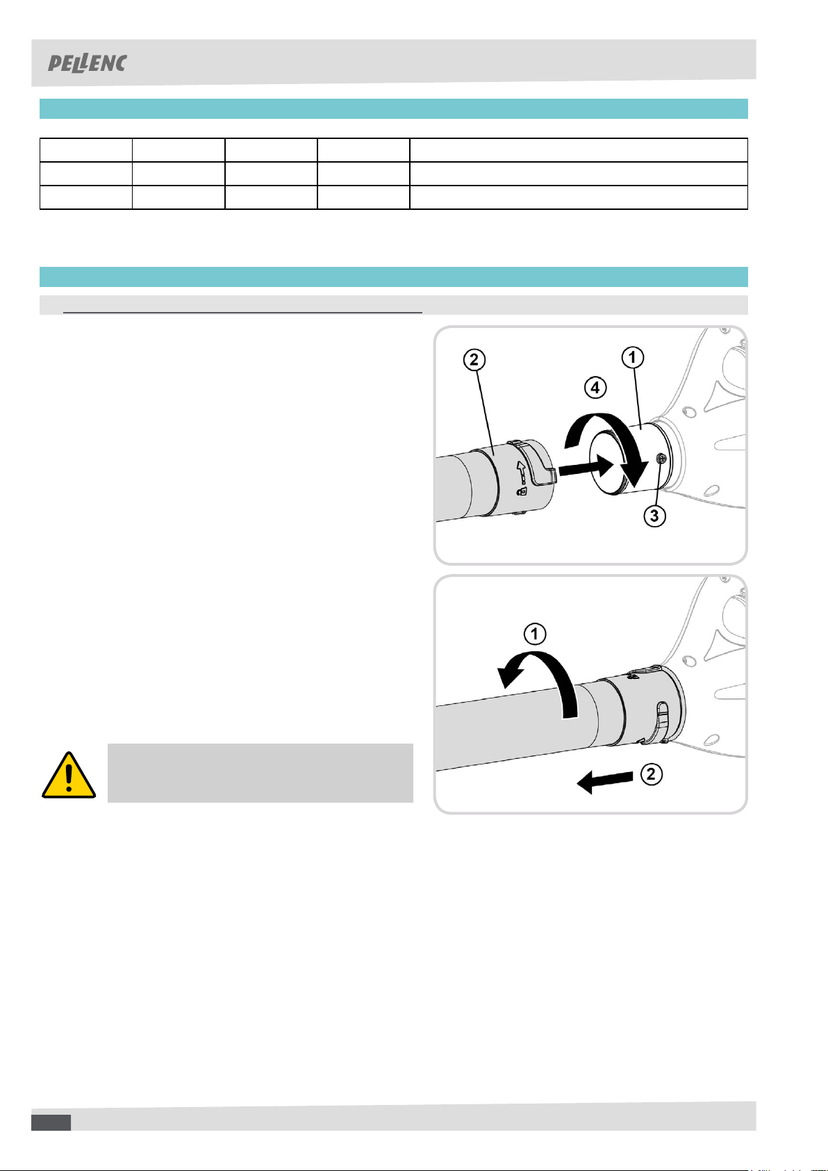
ʚ ASSEMBLY / DISASSEMBLY OF THE OUTLET BLOWING NOZZLE
ASSEMBLY
Fit the blowing tube (1) in outlet blowing nozzle (2) up
to the locking stud (3).
Make a quarter turn in the direction shown (4) to lock the
outlet nozzle (2).
REMOVAL
Make a quarter turn in the direction shown (1) to unlock
the outlet nozzle.
Remove the blowing tube from the outlet blowing nozzle in
the direction indicated (2).
WARNING
Never operate the tool unless the outlet
nozzle is fully assembled and locked.
121212
12
Page 13
USER GUIDE AIRIon 3 BLoWER
57_147010_A
■ PUTTING THE TOOL INTO SERVICE
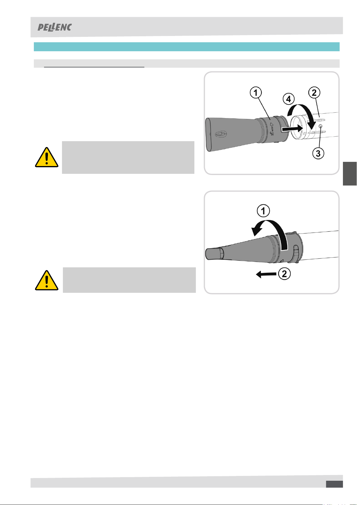
ʚ ADDING/REMOVING THE NOZZLE PLATE
ASSEMBLY
Push the at nozzle (1) onto the end of the outlet blowing
nozzle (2) as far as the stud (3).
Make a quarter turn in the direction shown (4) to lock
the at nozzle.
REMARK
The flat nozzle can only be fitted on the
standard outlet nozzle with a diameter of 75
mm.
REMOVAL
Make a quarter turn in the direction shown (1) to unlock
the at nozzle.
Remove the at nozzle from the outlet blowing nozzle (2).
There is hole on the at nozzle so that it can
be hooked on the snap hook accessory carrier
(see page 8).
131313
13
Page 14
USER GUIDE AIRIon 3 BLoWER
57_147010_A
■ PUTTING THE TOOL INTO SERVICE
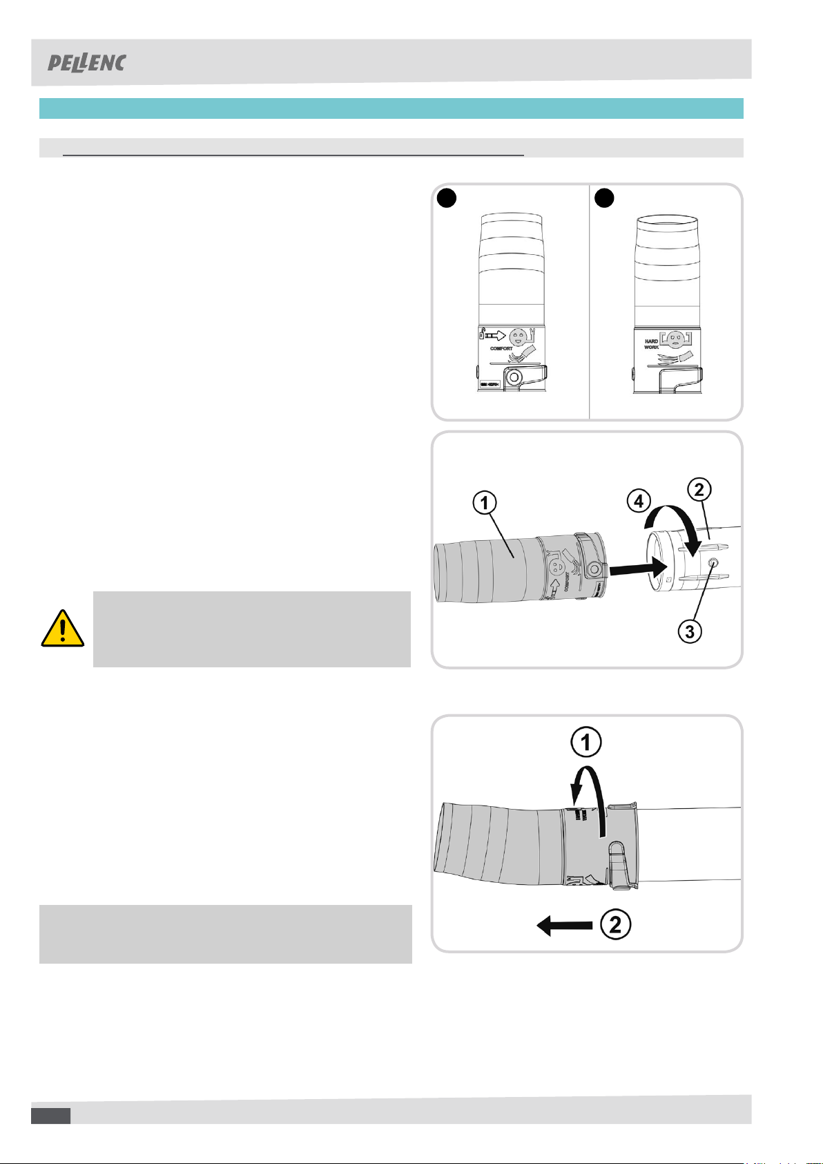
ʚ ASSEMBLY / DISASSEMBLY OF THE ERGONOMIC ELBOWED NOZZLE (OPTIONAL]
ASSEMBLY
Choose the working position for the ergonomic elbowed
nozzle according to the blowing work to be performed:
- Detail A: 'COMFORT' position.
- Detail B: 'HARD WORK' position.
Push the ergonomic elbowed nozzle (1) onto the end of
the outlet blowing nozzle (2) as far as the stud (3).
Make a quarter turn in the direction shown (4) to lock the
ergonomic elbowed nozzle (1).
A B
REMARK
The ergonomic elbowed nozzle can only be
fitted on the standard outlet nozzle with a
diameter of 75 mm.
REMOVAL
Make a quarter turn in the direction shown (1) to unlock
the ergonomic elbowed nozzle.
Remove the ergonomic elbowed nozzle from the outlet
blowing nozzle (2).
There is hole on the ergonomic elbowed nozzle so that
it can be hooked on the snap hook accessory carrier
(see page 8).
141414
14
Page 15
USER GUIDE AIRIon 3 BLoWER
57_147010_A
■ PUTTING THE TOOL INTO SERVICE
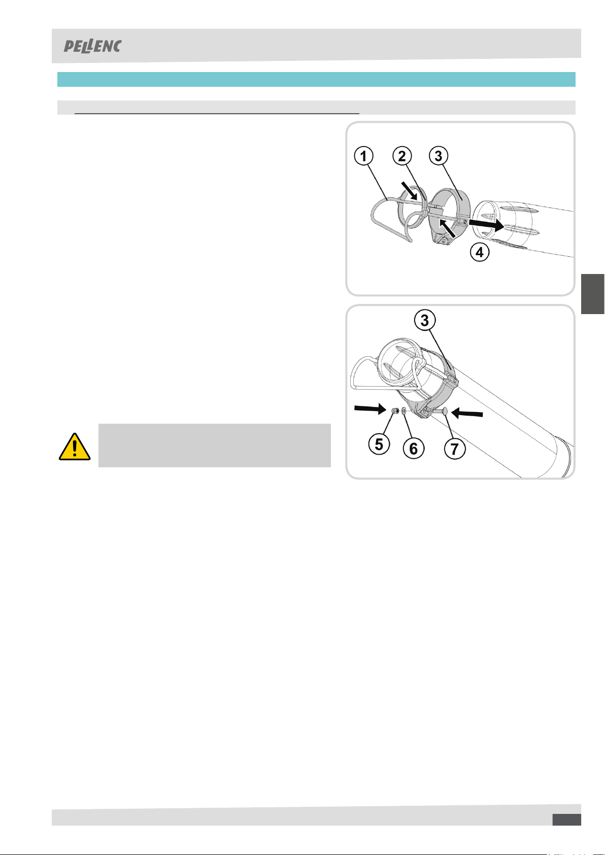
ʚ ASSEMBLY / DISASSEMBLY OF THE BLOWER SCRAPER (OPTIONAL)
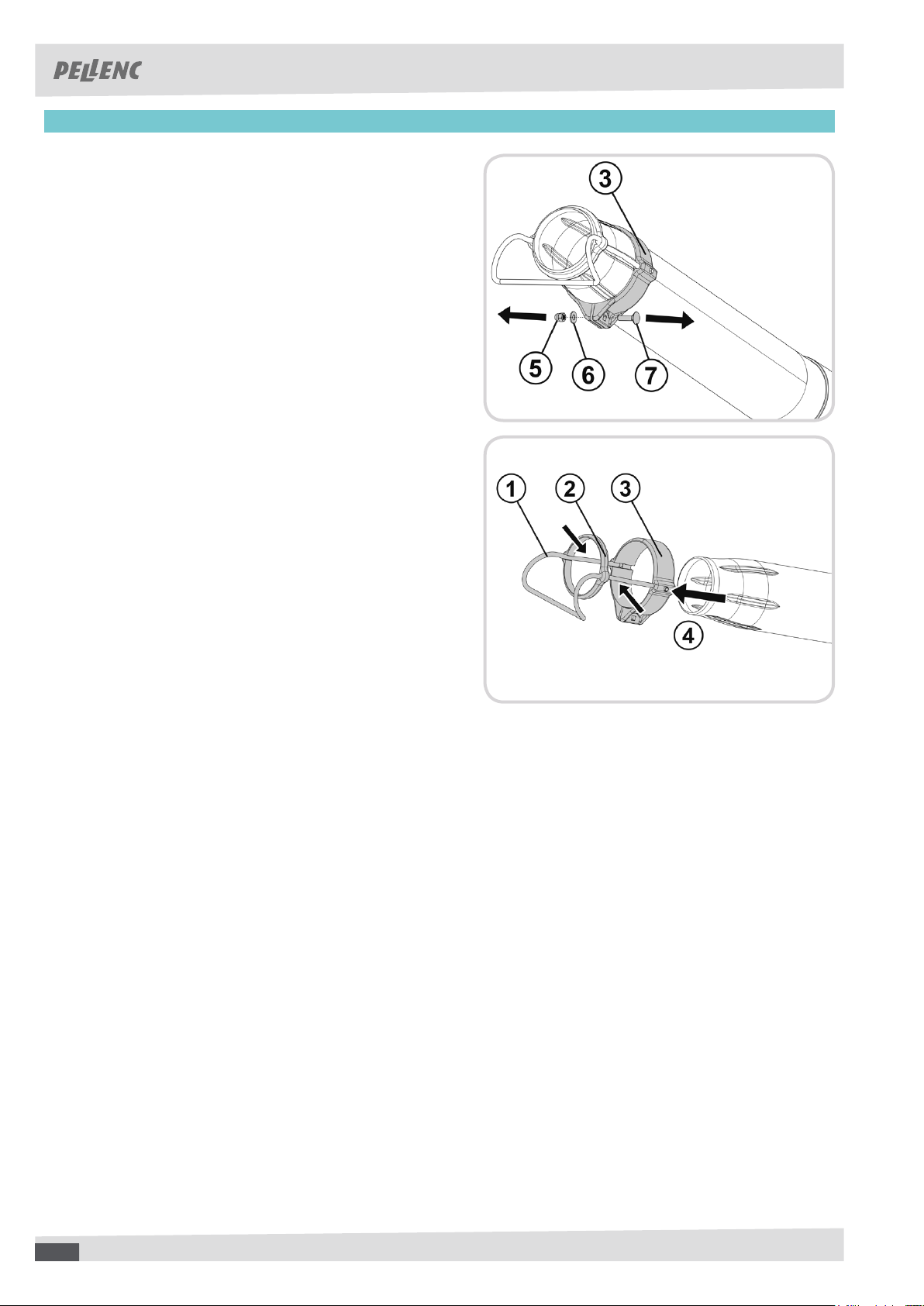
ASSEMBLY
Set up the wire scraper (1) in the guide ring (2) and the
support ring (3) by pressing on the rods.
Align the rods on the wire scraper (1) with the notches
and clip the unit into the outlet blowing nozzle (4).
Install the bolt (7), the washer (6) and the nut (5) in the
support ring (3).
Tighten the nut (5) to hold the support ring (3).
REMARK
The blower scraper can only be tted on the
outlet nozzle with a diameter of 65 mm.
151515
15
Page 16
USER GUIDE AIRIon 3 BLoWER
57_147010_A
■ PUTTING THE TOOL INTO SERVICE
REMOVAL
Remove the nut (5), the washer (6) and the bolt (7) from
the support ring (3).
Remove the assembly from the outlet blowing nozzle (4).
Disassemble the wire scraper (1) from the support ring
(3) and the guide ring (2) by pressing on the rods.
161616
16
Page 17
USER GUIDE AIRIon 3 BLoWER
57_147010_A
■ PUTTING THE TOOL INTO SERVICE
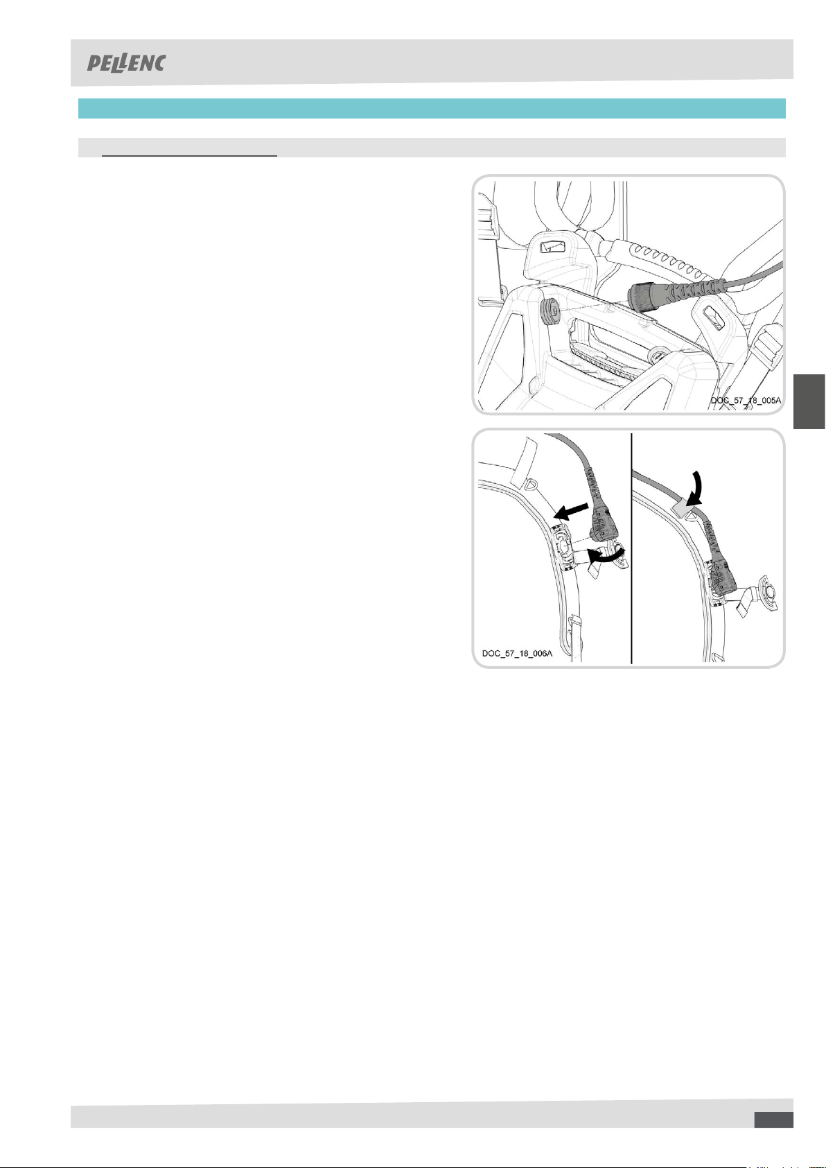
ʚ CONNECTING THE EXTENSION
The extension makes it easy to connect the AIRION 3 using
its quick connector. There are 2 types of extension, depending
on the battery used:
• 700, 1100 Battery: 5-pin connector
• 1200, 1500 Battery: 9-pin connector
Connect the connector (5- or 9-pin) for the extension
on the battery.
Lock the connector by screwing the safety ring
Depending on the battery model and the connector's
position on it, pass the extension through one of the straps
or the belt.
Insert the pin of the quick connector into the harness
buckle
Give the quick connector one quarter of a turn to keep
it in position.
171717
17
Page 18
USER GUIDE AIRIon 3 BLoWER
57_147010_A
■ START-UP AND OPERATION
ʚ HOLDING THE TOOL
The blower is designed to be operated with one hand.
The user can carry it holding the control handle with the left or right hand.
Always walk slowly while working.
Always check the blowing nozzle outlet area.
ʚ PREPARING THE BATTERY FOR USE
Refer to the notice for the Pellenc tools battery.
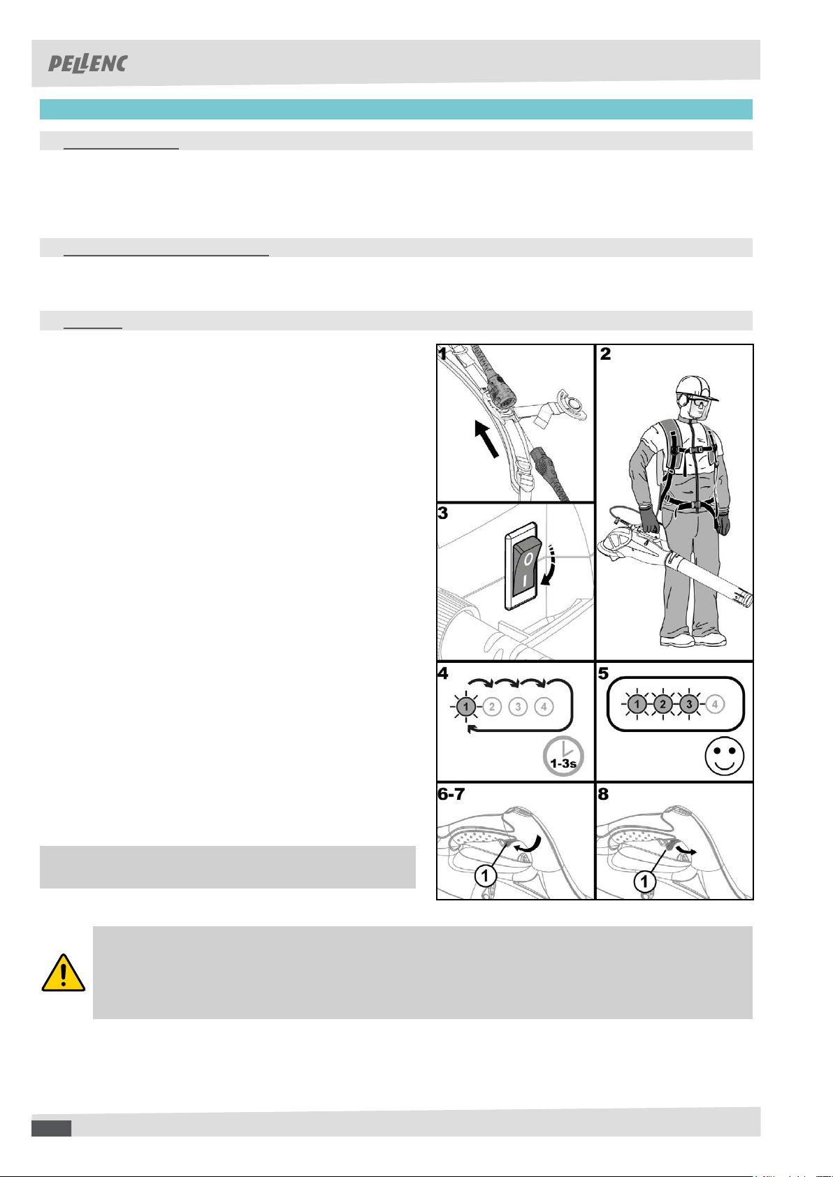
ʚ STARTING
Before start-up, make sure that the blower is in perfect condition
to guarantee safe operation.
Connect the tool power supply cable to the extension
attached to the harness and connected to the battery.
Hold the tool in its operating position, with the outlet
blowing nozzle pointing to the ground.
Turn the on-off switch on the Pellenc tool battery to "I".
The battery beeps 3 times to say that the tool has been
recognised.
The LEDs on the handle light up in sequence for one
to three seconds.
As soon as one or more LEDs are no longer blinking, the
battery is recognised and the tool is ready to work.
Press the control trigger (1) to start the blower. Walk
slowly while blowing the leaves, green waste or urban
garbage from one side to another.
The blower speed varies according to the pressure on
the trigger.
Release the trigger (1) to stop the blower.
The progressiveness of the control trigger allows
precise and instantaneous control of the air ow.
CAUTION
Make sure you keep sufcient distance (at least 30 cm) between the air intake and any volatile
source (grounds, walls, roofs, etc.), such as sand, gravels, liquids, etc.
These objects are likely to be drawn, pass through the air intake grille, damage your equipment
and be high-speed projected.
181818
18
Page 19
USER GUIDE AIRIon 3 BLoWER
57_147010_A
■ START-UP AND OPERATION
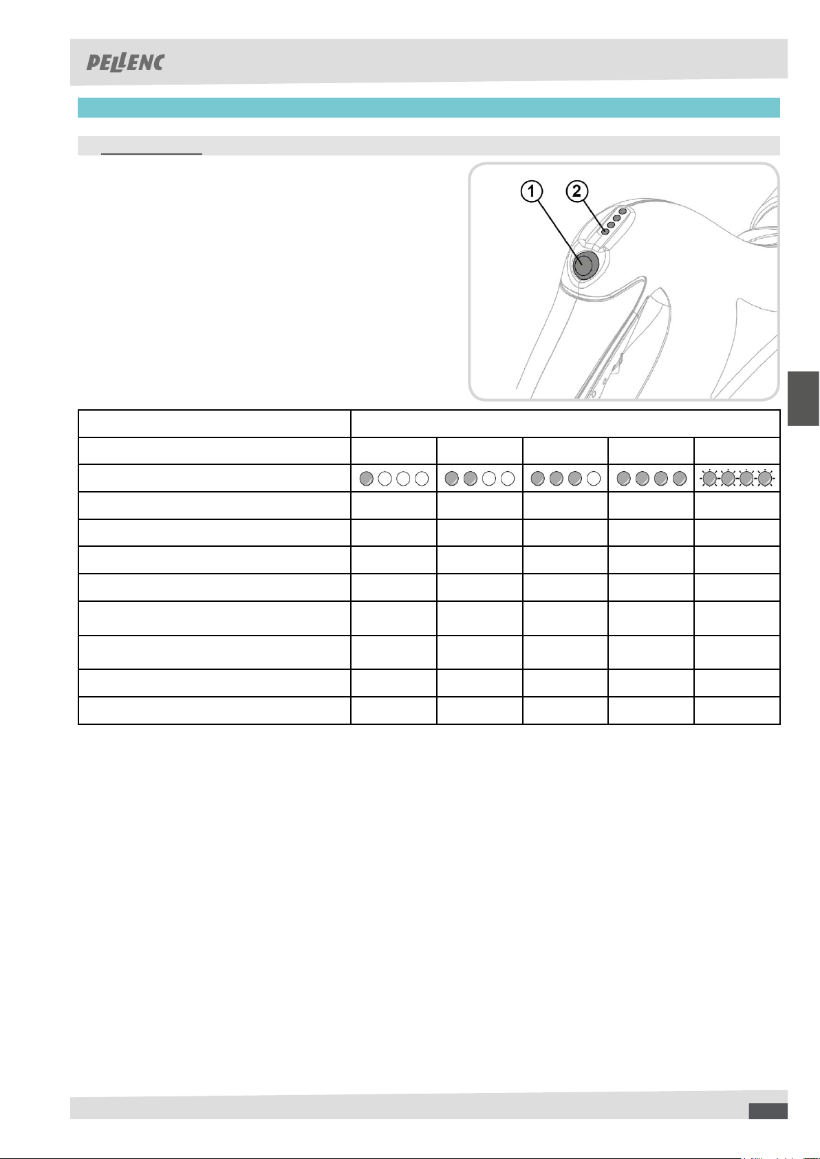
ʚ SPEED SELECTOR
Your blower is equipped with a speed change system. This
system is used to optimize and vary the air ow power using
the selector (1) on the handle.
When the blower is energized, the four indicator lights on the
handle (2) indicate the selected speed.
TOOL + STANDARD NOZZLE
Selected speed Speed 1 Speed 2 Speed 3 Speed 4 Boost
Indicator light status
Power (W) 150 380 500 600 940
Battery life (min) * 395 160 120 100 63
Max. airow speed (m/s) ** 33 47 52 55 63
Max. airow speed (m/s) *** 37 52 56 60 69
Max. airow speed with accessories (m/s)
****
Max. airow speed with accessories (m/s)
*****
Actual ow rate (m3/h) ** 490 690 760 815 920
Effective thrust (N) ** 5 10 12 13,5 18
* With a 1100 battery
** with a standard outlet blower nozzle with a diameter of 75 mm
** with an outlet blower nozzle with a diameter of 65 mm
**** with a at nozzle attachment
***** with an ergonomic angled nozzle accessory
37 52 57 60 69
34 48 51 57 64
191919
19
Page 20
USER GUIDE AIRIon 3 BLoWER
57_147010_A
■ START-UP AND OPERATION
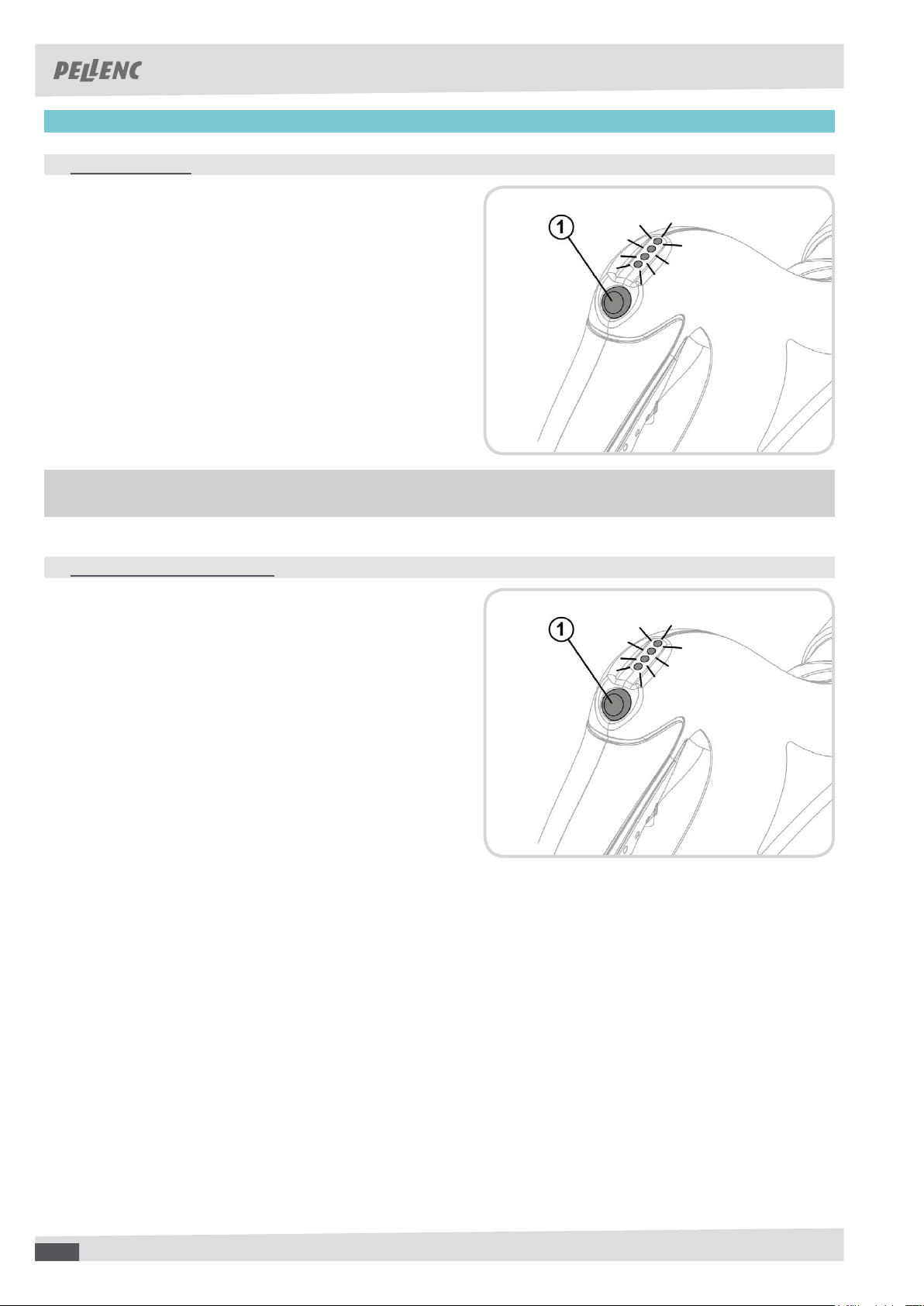
ʚ "BOOSTER" MODE
The blower has a "booster" mode which gives the maximum
power (940W) instantly. The airow speed and rate is then at
a maximum with the standard nozzle.
This mode is available for each speed.
Hold the selector button down (1) to switch to the "booster"
mode. The mode is activated instantly, 4 LEDs flash
simultaneously.
Release the button, the tool stays in "booster" mode.
A second press causes it to return to the initial speed.
Only use the "booster" mode temporarily and in case you need it (stuck debris, etc.) in order to limit the
blower power consumption.
ʚ ‘BATTERY LIFE READING’ MODE
For identifying the charging level of the battery, the tool has a
‘battery life reading’ mode
To activate the ‘battery status display’ mode:
Press the selector button for 2 seconds
The LEDs then indicate the charging level of the battery:
4 LEDs: battery is 75-100% charged
3 LEDs: battery is 50-75% charged
2 LEDs: battery is 25-50% charged
1 LEDs: battery is 0-25% charged
2020202020
Page 21
57_11_008B
USER GUIDE AIRIon 3 BLoWER
57_147010_A
■ START-UP AND OPERATION
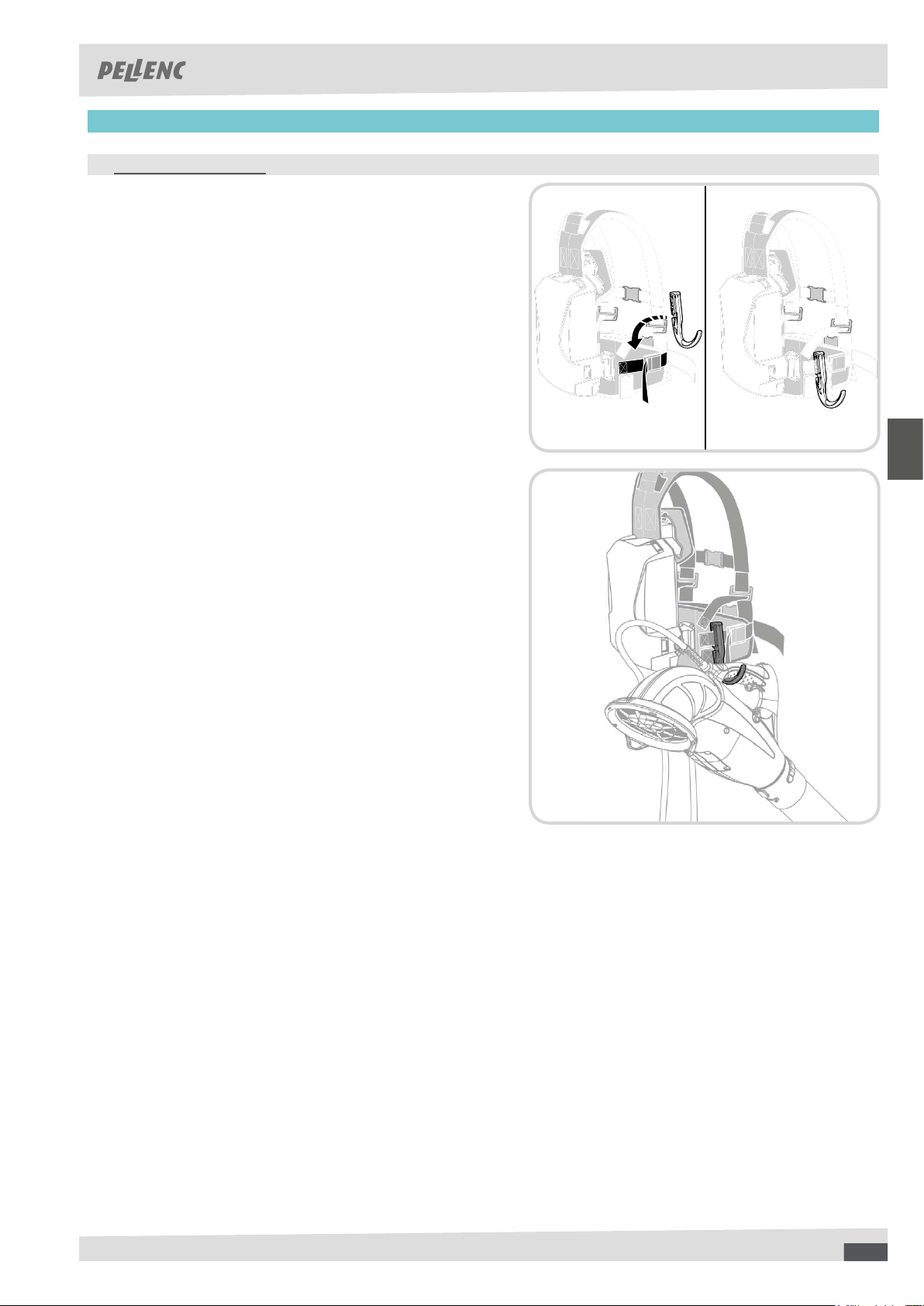
ʚ CARRYING (OPTIONAL)
Install the carrying hook on the lateral strap of the equipment
carrier vest.
Attach the blower to the carrying hook.
212121
21
Page 22
USER GUIDE AIRIon 3 BLoWER
57_147010_A
■ START-UP AND OPERATION
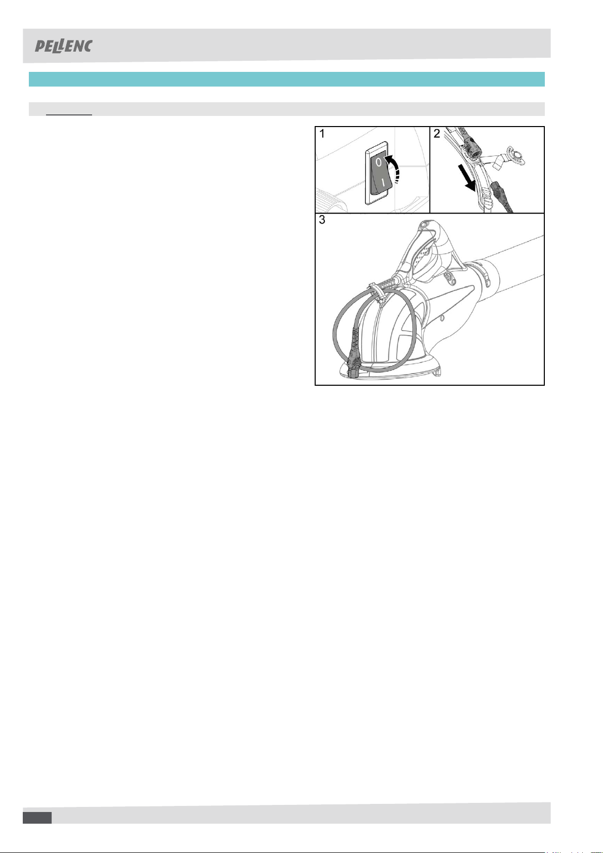
ʚ AFTER USE
Flip the ON/OFF switch of the Pellenc power tool battery
to OFF ‘0’
Disconnect the quick connector
Make 2 loops with the cord and attach it at the rear of
the handle with the carrying hook (see picture).
222222
22
Page 23
56_10_016A
USER GUIDE AIRIon 3 BLoWER
57_147010_A
■ SERVICING
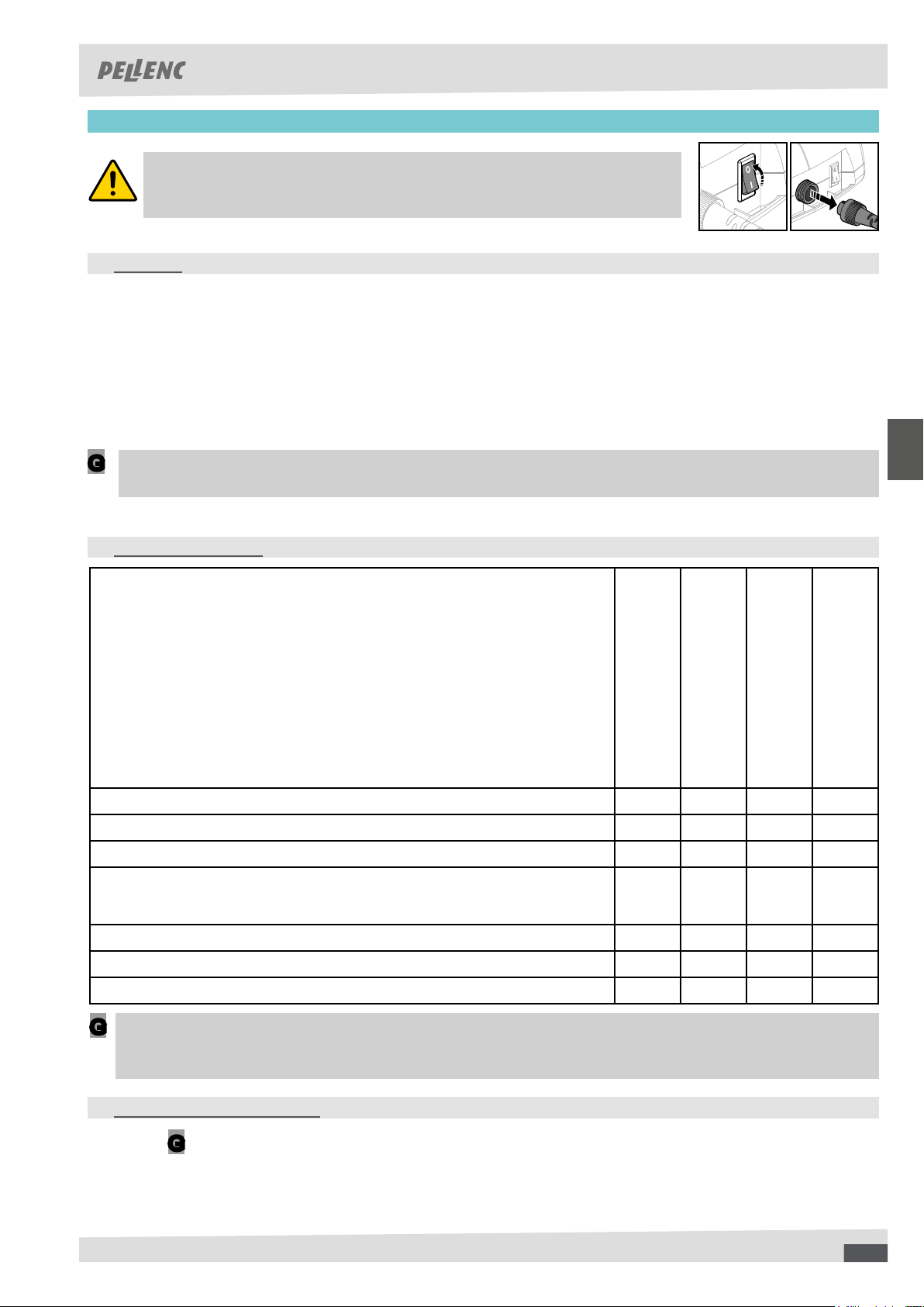
WARNING:
Before working on the tool, check that the On / Off switch is in the off
position «0» and disconnect the battery power lead.
ʚ CLEANING
Keep your blower clean by wiping it regularly with a soft moist cloth.
Using an air compressor, (10 bars), blow the tool, the grille and the propeller on a regular basis to limit fouling.
Check that the whole air duct (from the intake to the outlet) is not obstructed.
Ensure that air intake grille holes are not obstructed.
Replace the inlet screen in case of damage, even if it is partial.
Check the condition of the rotor. If a replacement is necessary contact your PELLENC distributor.
CAUTION:
G
Never use solvents (Trichlorethylene, White Spirit, gasoline, etc) to clean the tool.
ʚ SERVICING INTERVALS
After use
Each time the tool is used
Clean the tool X
Visually inspect the tool X
Check for clogging of the grid; clean if necessary X X
Check the rotor:
• clean if necessary
• replace if necessary (by an authorised PELLENC distributor)
Check the battery charge level X
Safety label replacement X
Send the tool to an approved dealer for inspection X
X
Each year or when necessary
REMARK:
G
Have your blower overhauled every 400 hours or at least once a year.
When the tool is stored, it must be clean and the battery must be charged.
ʚ INSTRUCTIONS FOR REPAIRING
CAUTION!
Only perform the maintenance and servicing interventions described in this manual.
More important repairs can only be carried out by an approved Pellenc dealer.
G
2323232323
Page 24

USER GUIDE AIRIon 3 BLoWER
57_147010_A
■ SERVICING
ʚ ACCESSORIES:
Air intake grille: 127757
Snap hook to carry accessories: 131701
Carrying strap: 110002
Flat nozzle: 122865
Carrying hook: 86708
Extension for the battery: 136892
Extension for the 1500 battery: 133179
ʚ STORAGE
- Always make sure the tool is clean and its battery is charged before storing it.
- Store the tool away from humidity and dust.
- Store the tool in a safe place, out of reach of children and unauthorized persons.
242424
24
Page 25

■ INCIDENTS
Repaired by
Solutions
Checks
User
Switch on the battery switch
Battery switch
dealer
PELLENC approved
Change the cord
Check the cord’s condition
User
Recharge the battery
completey discharged
Check that the battery is not
dealer
PELLENC approved
points
Change the electronic
board if the LEDs remain
verication of the previous
off after commissioning and
dealer premises
At PELLENC approved
dealer
PELLENC approved
Change the trigger or sensor
dealer premises
At PELLENC approved
dealer
PELLENC approved
Change the electronics board
dealer premises
At PELLENC approved
User
distributor
PELLENC
authorised
procedure.
Repeat the starting
cord to the battery,
Check the connection of the
Change the cord
cord
Check the condition of the
distributor
PELLENC
authorised
Change the electronic board
distributor
At an authorised PELLENC
Battery off
Probable cause
status
Indicator light
switch position
Battery start/stop
Symptoms
Out
0
Battery
The power cord is sectioned
Out
Electronic board
A trigger no longer functions
I
start
The tool does not
Electronic board
On
Battery not recognized
Faulty power cord
off
Flashing then
Electronic board defect
Page 26

■ INCIDENTS
Repaired by
PELLENC approved
Solutions
Change the trigger or
Checks
At PELLENC approved dealer
dealer
sensor
premises
dealer
PELLENC approved
Change the cord
cord
Check the condition of the
User
Allow tool to cool for
approximately 5 minutes
4 beeps on the battery
Recharge the battery (if less
When stopped, check the
User
than 10%)
on the side display
battery charge level indicated
User
Clean the duct
Check the condition of the duct
User
Clean or replace the rotor
Check the condition of the
rotor
User
Clean or replace the grille
grille
Check the condition of the
User
Clean the rotor
Check the condition of the
dealer
PELLENC approved
Replace the rotor
rotor
User
Clean the grill
Allow the tool to cool down
grille
Check the condition of the
Probable cause
A trigger no longer functions
status
Indicator light
start/stop switch
Condition of battery
On
limit
The power cord is sectioned
The tool has reached its temperature
Out
I
The battery is discharged
Dirty or damaged rotor
Air ow duct obstructed or blocked (air
intake elbow, blowing tube, nozzle, etc.)
On
I
Blocked air intake grille
On
I
The tool is hot
Dirty or damaged rotor
Cooling mode in operation
On
and
convergent
I
Symptoms
during use
The tool stops
The blower makes
vibrates abnormally
an unusual noise or
the air ow
Loss of efciency of
unavailable
The tool works, the
boost is temporarily
Page 27

■ PELLENC S.A. WARRANTY AND AFTER SALES SERVICE
Legal warranty
Warranty against latent defects
Apart from the commercial warranty provided for under Article II, Article 1641 of the Civil Code provides that "the seller is bound to a warranty on account of latent defects
of the object sold which render it unt for the use for which it was intended, or which would impair said use to the extent that the buyer would not have acquired it, or would
only have given a lesser price for it, had he known of them".
Article 1648 of the Civil Code "The action resulting from latent defects must be brought by the purchaser within two years after the discovery of the defect. "
Legal warranty of conformity
Article L.217-4 of the Consumer Code "The seller delivers goods in conformity with the contract and is liable for defects of conformity existing upon delivery.
The seller is also liable for any lack of compliance resulting from the packaging, assembly or installation instructions whenever its contractual liability is engaged in this
regard or the latter are carried out under its responsibility
Article L.217-5 of the Consumer Code "The goods are comply with the contract:
1) If they are suitable for the purpose usually expected of similar goods and, where applicable:
- If it matches the description given by the seller and possess the qualities that were presented to the buyer in the form of a sample or model;
- If it has the qualities that a buyer can reasonably expect given the public statements made by the seller, the producer or its representative, especially in advertising or labelling;
2. Or, if it has the characteristics dened by mutual agreement of the parties or is t for any particular purpose that the buyer made known to the seller and that the latter
accepted.
Article L.217-12 of the Consumer Code "legal action resulting from lack of conformity lapses two years after delivery of the goods".
Pellenc Commercial Warranty
Contents
General Information
In addition to legal warranties, client users benet from the commercial warranty on PELLENC products covering the exchange and replacement of parts recognised out
of use, caused by machining defects, assembly defects or material defects, whatever the cause.
The warranty forms an inseparable whole with the product sold by PELLENC.
Spare Parts
The commercial warranty also covers original PELLENC spare parts, excluding labour and to the exclusion of certain parts of each product provided at delivery.
Duration of the warranty
General Information
PELLENC products are guaranteed under the commercial warranty as from delivery to the customer for a period of two (2) years for products connected to a PELLENC
battery, and for a period of one (1) year for other PELLENC products.
Spare Parts
PELLENC spare parts replaced under the product warranty are guaranteed under the commercial warranty as from delivery of he PELLENC product to the customer for
a period of two (2) years for products connected to a PELLENC battery, and for a period of one (1) year for other PELLENC products.
In the case of products connected to a Pellenc battery, parts that are replaced in the under the product warranty after the 12th month of use, are covered for a period of
one (1) year.
Warranty exclusions
Excluded from the commercial warranty are products that have been subject to abnormal use, or were used under conditions and for purposes other than those for which
they were manufactured, especially in the case of non-compliance with conditions stipulated in this user manual.
It does not apply in case of shock, fall, neglect, lack of supervision or maintenance or in case of transformation of the product. Also excluded from the warranty are products
that have been subject to tampering, alteration or modication by the client user.
Wear parts and/or consumables cannot be covered by the warranty.
Implementation of the commercial warranty
Product commissioning and commissioning declaration
The DISTRIBUTOR undertakes to complete the computer commissioning declaration form, no later than eight days after the delivery of the property to the user customer,
in order to activate the latter on the www.pellenc.com website under "warranties and training" in the "extranet" menu, using the identier previously provided to them by
PELLENC.
Failing that, commissioning declaration will not be effective and implementation of the PELLENC commercial warranty will not occur. As a consequence thereof, the
DISTRIBUTOR must ensure the nancial burden of its intervention under the warranty without being able to pass on the cost to the client user.
The DISTRIBUTOR shall also undertake to complete the warranty card or the certicate of warranty and commissioning for self-propelled equipment provided with the
product after having the client user sign and date it.
Paid after-sales service
General Information
Malfunctions, breakdowns, breakages resulting from misuse, neglect or improper maintenance by the client user as well as malfunctions resulting from normal wear of the
product are subject to the payment of after-sales service, even during the period of the legal and commercial warranty. After-sales service repairs that fall outside of the
legal and commercial warranty also include maintenance, adjustments, diagnostics of all types, and cleaning without the present list being exhaustive.
Wear parts and consumables
Wear parts and consumables also fall within the after-sales service.
Spare Parts
Paid after-sales service also covers original PELLENC spare parts, excluding labour and outside the legal and commercial warranty period.
In case of replacement of original PELLENC spare parts in the context of after-sales service, said latter are covered by a warranty of one year as from the installation date.
Page 28

■ "EC" DECLARATION OF CONFORMITY
MANUFACTURER PELLENC
ADRESS Quartier Notre Dame
84120 Pertuis (FRANCE)
PERSON/ENTITY AUTHORISED TO COMPILE THE
PELLENC
TECHNICAL DOSSIER
ADRESS Quartier Notre Dame
84120 Pertuis (FRANCE)
WE HEREBY DECLARE THAT THE MACHINE HEREINAFTER REFERRED TO AS :
GENERIC DENOMINATION HAND-HELD BLOWER
FUNCTION MAINTENANCE WORK IN GREEN SPACES AND ON PUBLIC ROADS
COMMERCIAL NAME AIRION 3
TYPE AIRION 3
MODEL AIRION 3
57R00001 - 57R49999
SERIAL No.
57S00001 - 57S49999
57T00001 - 57T49999
COMPLIES WITH THE RELEVANT PROVISIONS OF THE MACHINERY DIRECTIVE (2006/42/EC)
IS IN CONFORMITY WITH THE FOLLOWING OTHER DIRECTIVES AND/OR RELEVANT PROVISIONS :
- 2014/30/EU EMC Directive
- 2003/10/EC Noise Directive
- 2002/44/EC Vibrations Directive
- 2011/65/EU ROHS Directive
- 1907/2006 REACH Regulation
- 2012/19/EU WEEE Directive
THE FOLLOWING HARMONIZED EUROPEAN STANDARDS WERE USED :
- EN 60335-1 :2013
- EN 50636-2-100 : 2018
- EN 60529 :1991+A1 :2000+A2 :2013
- EN 55014-1 : 2012
- EN 55014-2 :2009
LES AUTRES NORMES ET SPECIFICATIONS TECHNIQUES SUIVANTES ONT ÉTÉ UTILISÉES :
- EN 61000-4-2 :2009
- EN 61000-4-3 :2011
Sound Level at the maximum operating rating
Symbol Value Unit Reference Comment
L
L
WAm
WAg
90 dB(A) 1 pW Measured sound power level
92 dB(A) 1 pW Guaranteed sound power level
The recording of the measured sound power level and of the guaranteed sound power level has been
performed according to a procedure in accordance with directive 2000/14/EC appendix V.
CONCLUDED AT PERTUIS, DATED 29/06/2018
JEAN MARC GIALIS
Deputy Managing Director
Page 29

 Loading...