

Page 1

USER’S MANUAL
9CH/16CH MPEG4
PS Series Digital Video Recorder
Ver. 2.0
555-AWest Lambert Rd. Brea, CA 92821
Tel: 714-672-0333, Fax: 714-672-0360
www.PelikanCam.com
About this user guide
Before installing and using this unit, please read this user guide carefully.
Be sure to keep it handy for later reference.
The specification and information are subject to change without notice for quality improvement.
Page 2
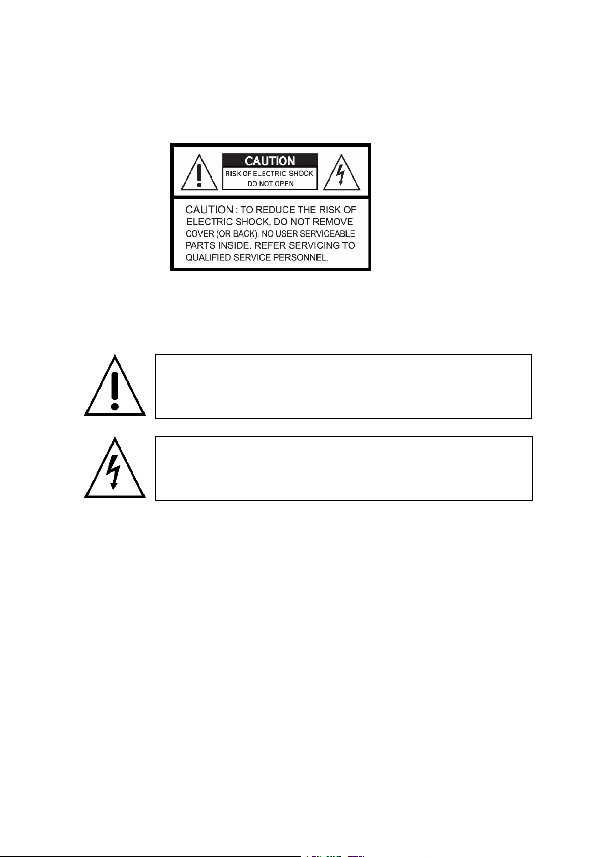
Safety Precautions
Explanation of Graphical Symbols
This symbol indicates the presence of important operating and
maintenance (servicing) instruction in the literature accompanying the
product.
This symbol indicates the presence of un-protected ”dangerous voltage”
within the product’s enclosure that may be of sufficient magnitude to
constitute a risk of electric shock to persons.
Cautions
This product has multiple-rated voltages (110v and 220v).
See installation instructions before connecting to the power supply.
This product uses a Lithium battery.
To avoid of risk of explosion, do not replace the battery on the main board by anything other
than a Lithium battery. Dispose of used batteries according to the manufacturer’s instructions.
This equipment and all communication wirings are intended for indoor use only.
To reduce the risk of fire or electric shock, do not expose the unit to rain or moisture.
2
Page 3

Warnings
Installation and servicing should be performed only by qualified and experienced personnel.
Power off the DVR when connecting cameras, audio or sensor cables.
The manufacturer is not responsible for any damage caused by improper use of the product or
failure to follow instructions for the product.
The manufacturer is not responsible for any problems caused by or resulting from the user
physically opening the DVR for examination or attempting to fix the unit. The manufacturer may
not be held liable for any issues with the unit if the warranty seal is removed.
3
Page 4

Rack Mount Instructions
The following or similar rack-mount instructions are included with the installation instructions:
A) Elevated Operating Ambient - If installed in a closed or multi-unit rack assembly, the operating ambient
temperature of the rack environment may be greater than room ambient. Therefore, consideration should
be given to installing the equipment in an environment compatible with the maximum ambient
temperature (Tma) specified by the manufacturer.
B) Reduced Air Flow - Installation of the equipment in a rack should be such that the amount of air flow
required for safe operation of the equipment is not compromised.
C) Mechanical Loading - Mounting of the equipment in the rack should be such that a hazardous
condition is not achieved due to uneven mechanical loading.
D) Circuit Overloading - Consideration should be given to the connection of the equipment to the supply
circuit and the effect that overloading of the circuits might have on over current protection and supply
wiring. Appropriate consideration of equipment nameplate ratings should be used when addressing this
concern.
E) Reliable Earthing - Reliable earthing of rack-mounted equipment should be maintained. Particular
attention should be given to supply connections other than direct connections to the branch circuit (e.g.
use of power strips)."
4
Page 5
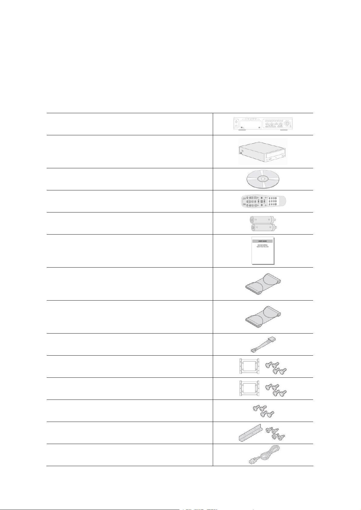
Product Components
The package contains the main unit and its components as specified below. When you purchase
the unit, please check to ensure the components specified below are included.
DVR Set
CDRW (Option)
Client Software CD
Remote Control
Battery1.5V (AAA x 2EA)
User Guide
IDE HDD Cable 80pin (1EA)
IDE CDRW Cable 40pin(1EA)-(Option)
Power Cable
HDD Brackets (2EA) & Screw (8EA)
CDRW Bracket(1EA) & CDRW Screw (8EA)
HDD & CDRW Bracket Screw (12EA)
Rack Mount (2EA)-(Option) & Screw (6EA)
Power Cord (110V or 220V)
5
Page 6
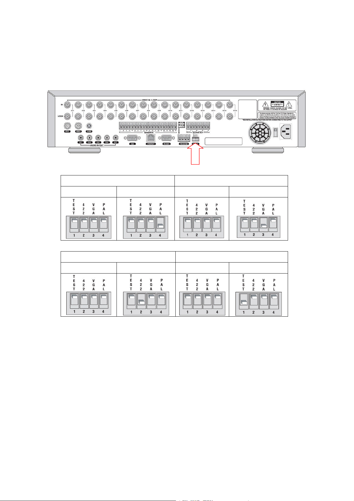
Video Signal Select & RS-422/485 Settings
Video mode Video output
NTSC PAL BNC VGA
RS-422/485 Select RS-485 Termination
485 422 ON OFF
NOTICE
1. Do not change the setting when the power is on. When the switch is changed, the DVR
should be rebooted to apply the new setting.
2. RS-485 Termination ON/OFF function is available on specific hardware version of the
system. Please inquiry the manufacturer.
6
Page 7

Compatible HDD Models
Company Capacity RPM Buffer Interface
80 GB 7200 RPM 2 M E-IDE
HITACHI
MAXTOR
SAMSUNG
Western Digital
160 GB 7200 RPM 8 M E-IDE
250 GB 7200 RPM 8 M E-IDE
500 GB 7200 RPM 8 M E-IDE
80 GB 7200 RPM 2 M E-IDE
200 GB 7200 RPM 2 M E-IDE
250 GB 7200 RPM 8 M E-IDE
300 GB 7200 RPM 16 M E-IDE
80 GB 7200 RPM 2 M E-IDE
160 GB 7200 RPM 2 M E-IDE
250 GB 7200 RPM 8 M E-IDE
300 GB 7200 RPM 8 M E-IDE
160 GB 7200 RPM 2 M E-IDE
200 GB 7200 RPM 8 M E-IDE
250 GB 7200 RPM 8 M E-IDE
80 GB 7200 RPM 2 M E-IDE
120 GB 7200 RPM 2 M E-IDE
160 GB 7200 RPM 2 M E-IDE
250 GB 7200 RPM 8 M E-IDE
SEAGATE
300 GB 7200 RPM 8 M E-IDE
400 GB 7200 RPM 8 M / 16M E-IDE
500 GB 7200 RPM 8 M / 16M E-IDE
750 GB 7200 RPM 8 M / 16M E-IDE
NOTICE
The brands and models of all HDD should be the same. If the brands and models of each HDD
are different with others, the DVR could not recognize HDD.
7
Page 8
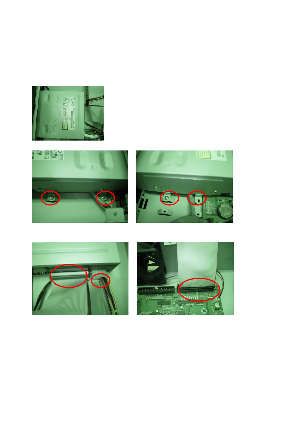
CDRW or DVD-Combo Installation Guide
1. Open the top cover of DVR set and Install the CDRW inside the DVR.
2. Fasten the screws on both side of CDRW as indicated in red circle below.
3. Connect the IDE CDRW 40pin cable and Power cable to the point on both CDRW and Main
board as indicated in red circle below.
4. CDRW JUMPER SETTING = MASTER
Compatible CD-RW model
LG GCE-8525B / GCE-8526B / GCE-8527B
Compatible DVD-Combo model
LG GCC-H23N
8
Page 9
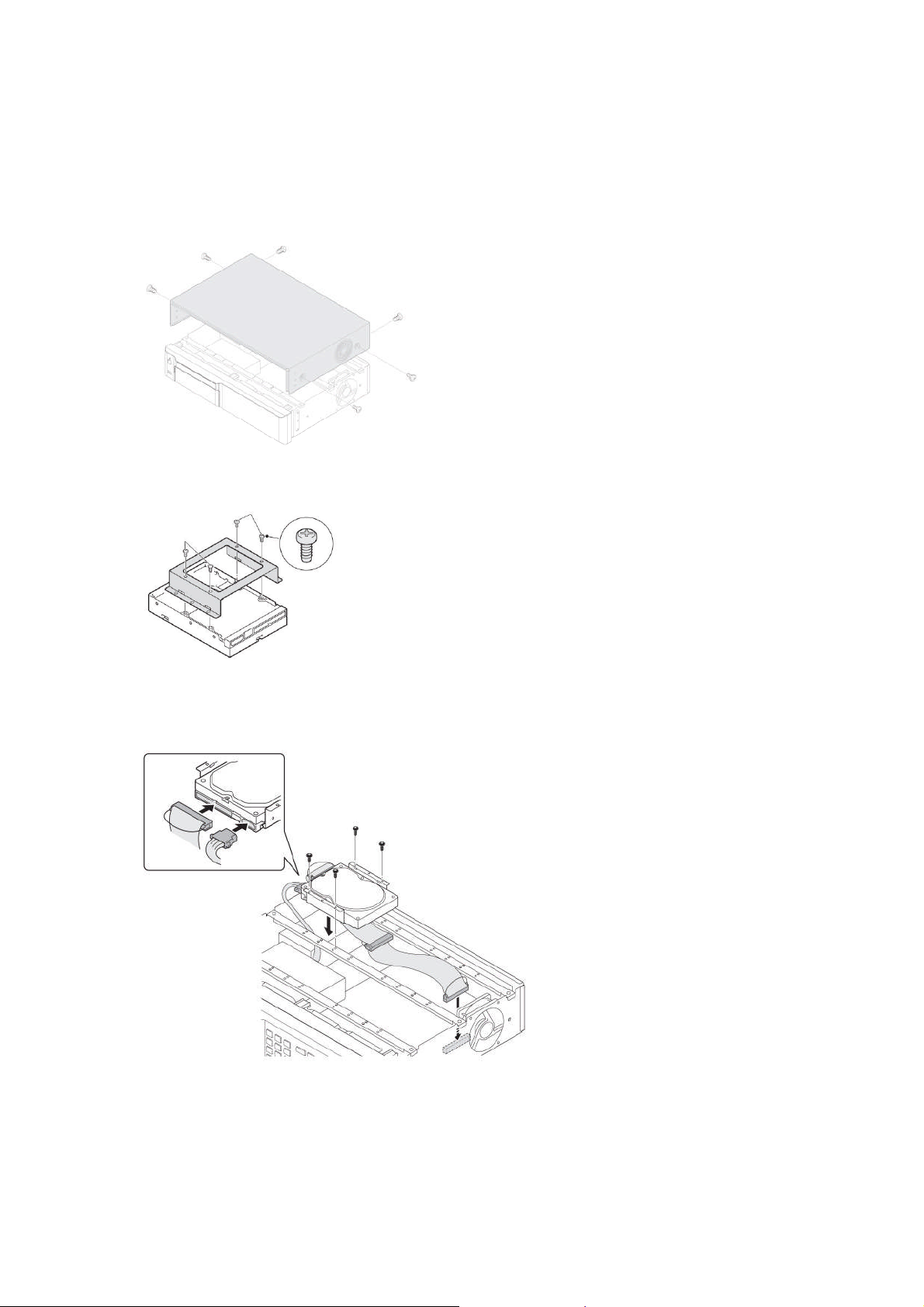
HDD Installation Guide
1. Unfasten the cover of the unit.
2. Fix the bracket to the hard disk using the supplied HDD mounting bracket screws.
3. Connect the supplied IDE HDD 80pin cable and Power cable to the hard disk and fix the
hard disk to the unit the supplied HDD fixing screws.
4. HDD JUMPER SETTING
1STHDD = MASTER
2ndHDD = SLAVE
9
Page 10
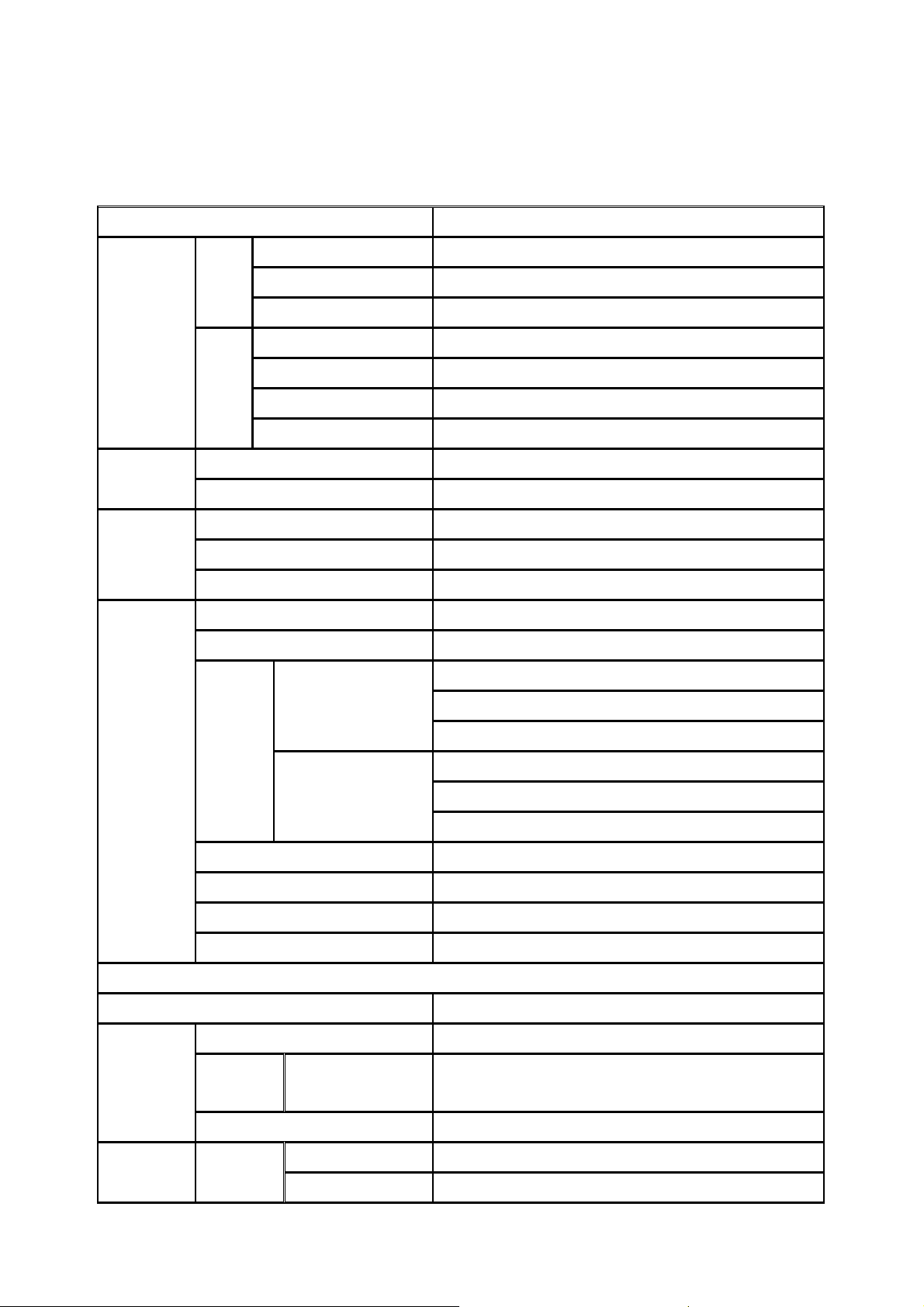
Specifications
ITEM DVR-9CH/16CH
Channel, Input Level 9/16CH, Composite 1.0Vp-p, 75 Ohm
Video
Audio
Alarm
Input
Output
Signal Format NTSC/PAL
Video Loss Check Yes
Main Monitor Output 1 CH BNC, 1 CH S-VIDEO, 1CH VGA
Output Level Composite 1.0Vp-p +_0.2, 75 Ohm
Signal Format NTSC/PAL & VGA
Etc Output 9/16CH Loop-back , 1CH SPOT
Input & Output 4 CH Line input & 1 CH Line output
Audio Codec G.711
Sensor Input 9/16 (NC/NO Selectable)
Alarm Output 4
Alarm Output By Alarm, Motion, Video Loss
Compression MPEG-4
Multi-operation TRIPLEX (Playback/Record/Network)
352x240
NTSC
704x240
Recording
Playback
Resolution
PAL
Recording quality grade 5 grades
Recording Mode Continuous / Schedule / Motion/ Sensor/ Manual
Motion Detection Motion detection setup by Grid
Pre & Post Recording Yes
Display
Frame Rate ( /Sec) NTSC: 30fps/ch, 60 fields / PAL: 25fps/ch, 50 fields
Multi-Decoding 1, 4, 9, 16
Playback
Speed
HDD
Fast Forward /
Reverse
Search Mode Event, Archive, Log
Interface Type EIDE/ATA133Storage Internal
Capacity of 1 HDD 1000GB
704x480
352x288
704x288
704x576
× 2, 4, 8
10
Page 11
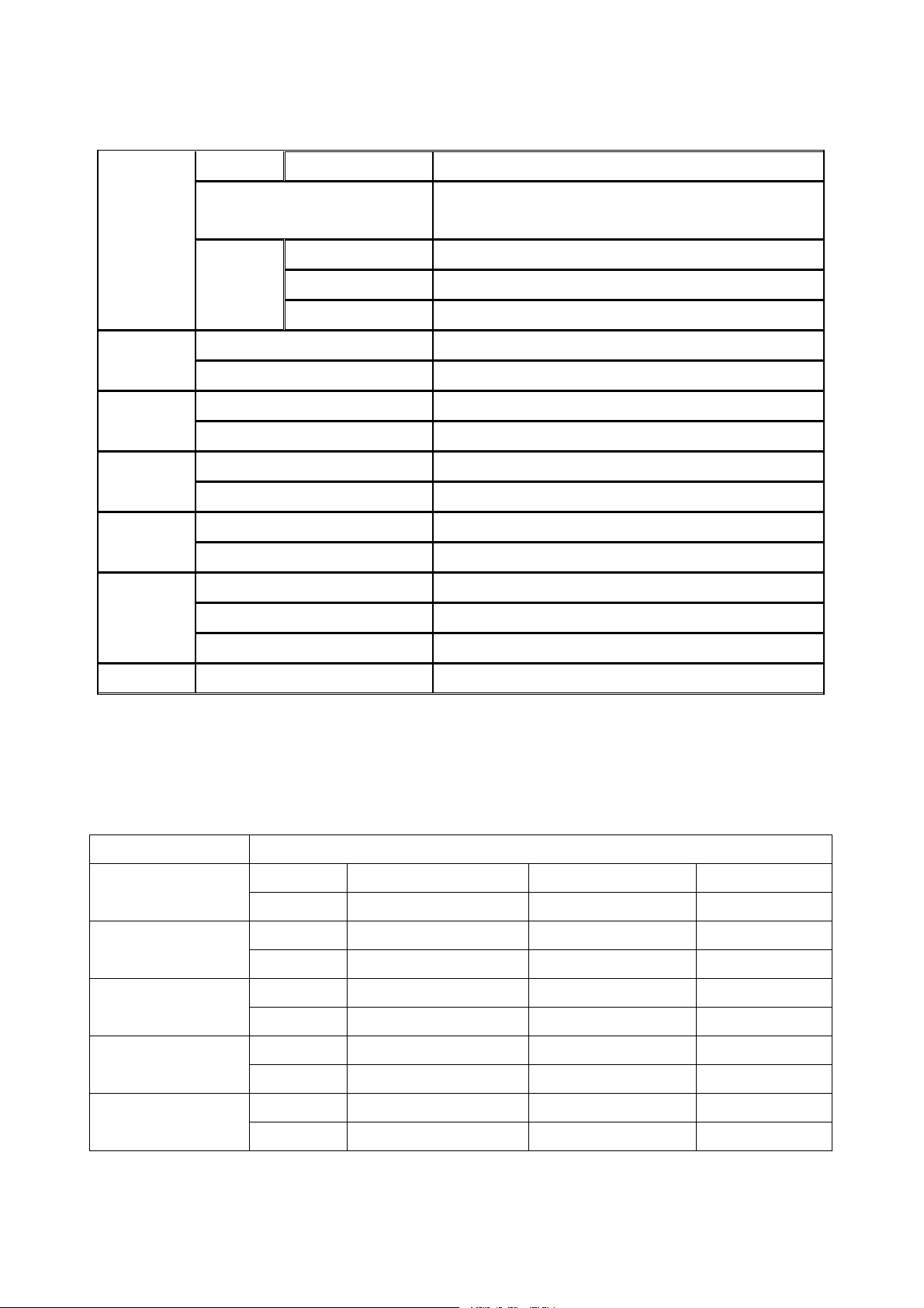
Max HDD Number 4
User I/F
Serial port
Network
Network
Client S/W
Additional
Functions
File system
USB 2.0 flash stick Still Image & AVI
Backup
Menu Display GUI
Input Method Front Keypad, Remote controller
Console & External Modem 1 RS-232C (9pin D-SUB connector)
Camera control 1 RS-485/422 (4 Terminal Block)
Dynamic IP support Yes
Network Interface 10/100 base-T Ethernet (RJ-45)
Functions Live, Search, Backup, PTZF Camera Control
Central Monitoring System Yes
DLS (Day Light Saving) Yes
Multi-Language Yes
S/W Upgrade USB 2.0 memory stick
CDRW Still Image & AVI
Network Moving picture & Still Image
NaFS: Own developed & Designed for never broken
by any power failure
Power Power Source 100~127V/200~240V, 50-60Hz
Recording performances and resolutions per models
MODEL Recoding performance (Max.)
PS-0912
PS-0924
PS-1612
PS-1624
PS-1648
NTSC
PAL
NTSC
PAL
NTSC
PAL
NTSC
PAL
NTSC
352x240: 120fps 704x240: 60fps 704x480: 30fps
352x288: 100fps 704x288: 50fps 704x576: 25fps
352x240: 240fps 704x240: 120fps 704x480: 60fps
352x288: 200fps 704x288: 100fps 704x576: 50fps
352x240: 120fps 704x240: 60fps 704x480: 30fps
352x288: 100fps 704x288: 50fps 704x576: 25fps
352x240: 240fps 704x240: 120fps 704x480: 60fps
352x288: 200fps 704x288: 100fps 704x576: 50fps
352x240: 480fps 704x240: 240fps 704x480: 120fps
PAL
352x288: 400fps 704x288: 200fps 704x576: 100fps
11
Page 12

Table of Contents
1. Features...............................................................................................................................14
2. Name, Function and Connection .......................................................................................15
2-1. Front Panel.................................................................................................................15
2-2. Rear Panel..................................................................................................................17
2-3 Remote controller ........................................................................................................18
3. Setting up the DVR .............................................................................................................19
3-1. Setup – Main Screen ..................................................................................................19
3-2. Setup – Display Mode.................................................................................................21
3-3. Setup – Recording Mode ............................................................................................22
3-3-1. Quick record setting.................................................................................................23
3-3-2 Recording Schedules................................................................................................24
3-4. Setup – Device Mode..................................................................................................25
3-4-1. ALARM-OUT............................................................................................................26
3-4-2. SPOT – OUT...........................................................................................................27
3-4-3 PTZ Setup ................................................................................................................27
3-4-4. Motion Zone Setup ..................................................................................................28
3-5. Setup – Storage Mode ................................................................................................29
3-6. Setup – System Mode.................................................................................................30
3-7. Setup – PASSWORD Mode........................................................................................33
3-8. Setup – Network Mode ...............................................................................................35
3-8-1. Ports........................................................................................................................36
3-8-2. Network Types.........................................................................................................37
3-8-2-1. LAN......................................................................................................................37
3-8-2-2. DHCP...................................................................................................................38
3-8-2-3. ADSL (PPPoE) .....................................................................................................38
3-8-3. Saving Setup of Network setup................................................................................39
3-9. Setup - CONFIG Mode ...............................................................................................39
4. Saving Setup.......................................................................................................................41
5. Live, Search, and Playback ................................................................................................42
5-1. Live Viewing Screen ...................................................................................................42
5-2. SEARCH Screen ........................................................................................................44
5-2-1. TIME-LINE Search...................................................................................................44
5-2-2. Event Search...........................................................................................................45
5-2-3. Go To First Time ......................................................................................................46
5-2-4. Go To Last Time ......................................................................................................46
12
Page 13

5-2-5. Go To Specific Time.................................................................................................46
5-2-6. Log List Search........................................................................................................46
5-2-7. Archive Search ........................................................................................................47
5-3. Play mode...................................................................................................................47
6. PTZ Control .........................................................................................................................48
7. Backup.................................................................................................................................49
7-1. Still Image backup onto USB flash memory or CD media............................................49
7-2. Video backup onto USB flash memory or CD media...................................................50
7-3. Transferring still images or video from the ARCHIVE list.............................................50
7-4. Playback of Backup Video ..........................................................................................51
7-4-1. Playback of backup video in AVI format...................................................................51
7-4-2. Playback of backup video in exclusive (NaFs) format..............................................51
8. Upgrading Firmware...........................................................................................................52
9. Network – By an exclusive viewer.....................................................................................53
9-1. Overview.....................................................................................................................53
9-2. Minimum PC requirements..........................................................................................54
9-3. Installing the program .................................................................................................54
9-4. Live viewer..................................................................................................................55
9-5. Search and Playback Viewer......................................................................................57
9-5-1. Backup ....................................................................................................................58
9-6. PC System configuration ............................................................................................58
9-6-1. General....................................................................................................................58
9-6-2. Site..........................................................................................................................59
9-6-3. Event.......................................................................................................................60
9-6-4. Record.....................................................................................................................60
9-6-5. Disk.........................................................................................................................61
10. Network – By an web-browser viewer .............................................................................63
10-1. Download Web Brower Viewer and Connection........................................................63
10-2. Main Features...........................................................................................................64
10-2-1. Live........................................................................................................................64
10-2-2. Search and Playback.............................................................................................65
APPENDIX ...............................................................................................................................66
A. How to open TCP port on Router?..........................................................................66
B. How to access DVR from Remote PC? ..................................................................66
B-1. How to access DVR from Remote PC in the same local network? ......................66
B-2. How to access DVR from Remote PC with IP address?......................................67
B-3. How to access DVR from Remote PC with DDNS service when DVR is linked on
Dynamic IP?...............................................................................................................67
13
Page 14

1. Features
● 9/16 channels real-time live display and 9/16 channels simultaneous playback.
● MPEG-4 - Unbeatable recording picture quality and compression ratio. Best format for minimizing
recording space and bandwidth requirements for network transmission.
● TRIPLEX - Simultaneous recording, playback and transmission via network
● NaFS (File System) - Designed to prevent data loss or corruption in the event of a power failure.
● Multiplexing operation
● Reliability - Real Time Operating System and simplified hardware as well as watchdog timer ensure
reliability.
● Individual channel recording and playback with different frame rate.
● High-quality live and playback resolution.
● Multi-site management - Supported by CMS application.
● Network features - remote live, playback, PTZF control, and backup.
● Network via LAN, DHCP,ADSL (Dynamic and Static IP address).
● 4 channels audio recording.
● User-friendly setup menu with graphic user interface.
● Easy to schedule complicated weekly recording plans.
● Motion detection – Use the 30x24 gridto definemotion zones for each camera.
● USB ports for JPEG, MPEG data backup and software upgrade using USB flash memory stick.
● Still image capture and review as JPEG format.
● Internal Pan/Tilt/Zoom/Focus controller.
● Easy operation with buttons on the front panel and an optional remote control.
● User verification by password certification.
● Video loss detection.
● Backup - Still-images or AVI data into USB flash memory stick, internal CDRW, and Network.
● Variety of Hard Drive Sizes - up to internally 3TB (750GB X 4 HDD) for long-term recording.
● Multi-Languages -User can easily select language from Setup menu.
● Various Video Output - VGA(800x600 24 Bit Color), S-VHS, SPOT
14
Page 15
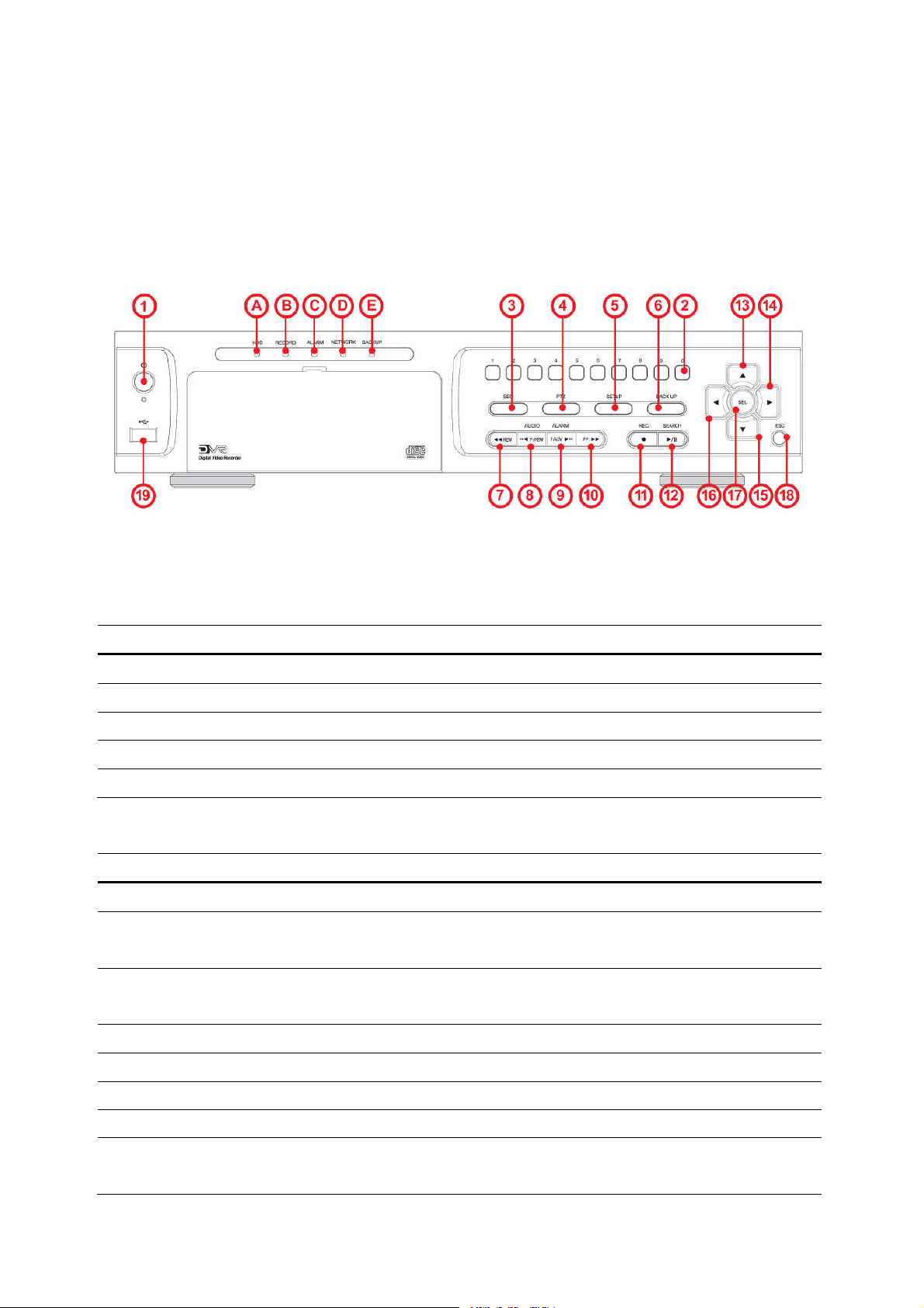
2. Name, Function and Connection
2-1. Front Panel
The following information will help you to operate the front panel controls.
Figure 2.1.1. Front panel
Table2.1.1. Indication lamps
NO. Name Description
A
B
C
D
E
NO Name Description
1
2
3
4
5
HDD
RECORD
ALARM
NETWORK
BACKUP
POWER
NUMBER
SEQ
PTZ
SETUP
Indicating that the system is accessing the hard disk.
Indicating that the system is recording video data.
Indicating that when sensor(s) is/are triggered or motion is detected.
Indicating that when Network client connects through the network.
Indicating that USB or CDRW storage device is stored images or video.
Table 2.1.2. Front panel buttons
POWER ON/ OFF
Channel keys. For channel 10, press the 0 key. For channel 11, press
the +10 and 1 key. For channel 16, press the +10 and 6 key.
Enable/disable the automatic sequence of display of channels in full
screen, quad, 9-split display mode.
Press to control Pan/Tilt/Zoom operations.
Press to enter SETUP menu.
6
7
8
BACKUP
REW
AUDIO
Press to capture video in jpeg format in live or playback mode.
Press to rewind the footage in playback mode.
Press to select audio mode such as SINGLE, MIX and MUTE.
MUTE- All of 4 channels.
15
Page 16

SINGLE- Highlighted channel only.
MIX- All of 4 channels.
8
9
9
10
11
12
13
14
15
16
F/REW
ALARM
F/ADV
FF
REC
SEARCH
PLAY/PAUSE
UP
RIGHT
DOWN
LEFT
Jump/Step backward. In playback mode, the playback position moves
60 seconds backward.
Press to enable/disable ALARM operation.
Jump/Step forward. In playback mode, the playback position moves
60 seconds forward.
Press to fast forward the footage in playback mode.
Press to start or stop manual recording.
Press to go to SEARCH menu in live display mode.
Press to play and pause the footage in playback mode.
Press to move up the menu in Setup mode.
It is also used as the number 1 when entering password.
Press to move right or to change the values in Setup mode.
It is also used as the number 2 when entering password.
Press to move down the menu in Setup mode.
It is also used as the number 3 when entering password.
Press to move left or to change the values in Setup mode.
17
18
19
SEL
ESC
USB Port
It is also used as the number 4 when entering password.
Press to select desired menu item or to store the setup value.
Press for temporary storage of the changed value or to return to the
previous menu screen.
To archive still-image or video into a USB memory and USB CDW or
upgrade firmware with USB memory stick.
16
Page 17
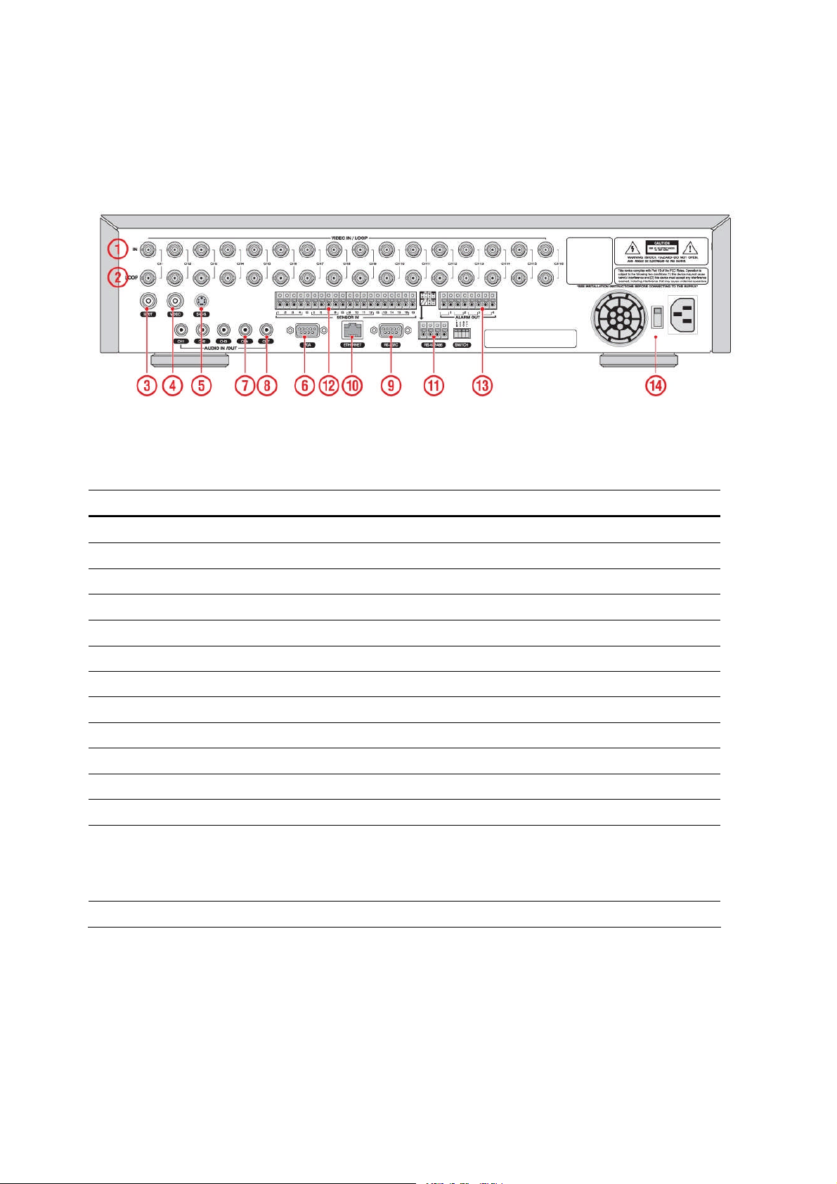
2-2. Rear Panel
Figure 2.2.1. Rear Panel
Table 2.2.1. Rear panel connections
NO Connection Purpose
1
2
3
4
5
6
7
8
9
10
11
12
13
14
VIDEO IN
VIDEO OUT
SPOT
VIDEO
S-VHS
VGA
AUDIO IN
AUDIO OUT
RS-232
LAN
RS-485/422
SENSOR IN
ALARM OUT
POWER
9/16 connectors for video input. (NTSC/PAL)
9/16 connectors for video output. (Loop Back)
Composite video output for spot monitoring.
Composite video output in NTSC or PALformat.
S-VHS output.
Connector for VGA monitor.
4 connectors for audio input.
1 connector for audio output.
For engineering use only.
RJ-45 connector for LAN connection.
For camera control use.
8/16 connectors for sensor device connection.
4 connectors for alarm device connection.
Provides simple On/Off switching by using relay. 0.5A/125V,
1A/30V
Connect AC115/230V power cable.
17
Page 18

2-3 Remote controller
POWER
DISPLAY
F/REW
PLAY
F/ADV
BACK UP
FF
ALARM
SETUP
AUDIO
LOCK
SEQ
RECORD
SEARCH
Power On/Off
Display of Full, Quad or 9 split view
Jump 60 seconds backward
Play/Pause
Jump 60 seconds forward
Back up
Fast Forward
Disable alarm operation
Setup menu screen
Disable, Mute or Highlighted
channel only
Locks functions
Sequence of Full or Quad view
Manual recording
Search menu screen
DIRECTION
SELECT
ID
ESC
PTZ
NUMBER
CHANNEL
Direction or number 1 to 4
Enter
DVR ID
(ID Button + DVR ID number)
Esc
PTZ menu screen
Channel 1 to 9
Channel 10 to Channel 16
10CH->press number 1 and 0
11CH-> press number 1 and 1
12CH-> press number 1 and 2
13CH-> press number 1 and 3
14CH-> press number 1 and 4
15CH-> press number 1 and 5
16CH-> press number 1 and 6
18
Page 19
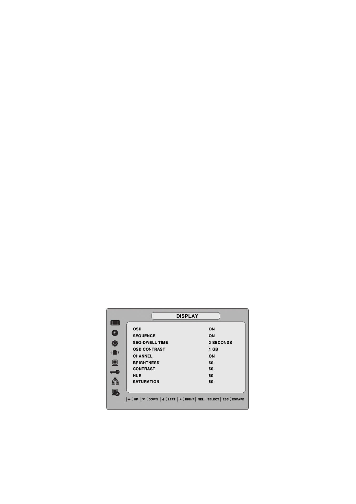
3. Setting up the DVR
The following sections detail the initial setup of the DVR
3-1. Setup – Main Screen
When the SETUP button is pressed, the DVR will ask for a password. The default password is
1111, which can be entered by pressing the up button 4 times and then pressing the SEL button.
It is recommended that a new password be assigned to protect the system. The procedure for
assigning a password is found in section 3.7. After a password has been assigned, enter the
password by using the direction keys (representing 1, 2, 3, & 4) and press the SEL button for
the password validation. Once the password is entered the Setup screen as shown in Figure
3.1.1. will appear. Navigate through the menu items and press the SEL button to enter the subcategory menu.
Figure 3.1.1. Setup screen
Table 3.1.1. Setup menu configuration
19
Page 20

DISPLAY OSD
SEQUENCE
SEQ-DWELL TIME
OSD CONTRAST
CHANNEL DISPLAY, BRIGHTNESS, CONTRAST, HUE, SATURATION
RECORD RESOLUTION
CHANNEL FRAME RATE, QUALITY, RECORDING, SENSOR RECORDING,
DEVICE ALARM OUT
SPOT -OUT
PTZ
CHANNEL MOTION ZONE, MOTION SENSITIVITY
KEY TONE
REMOTE CONTROL ID
SENSOR TYPE
STORAGE OVERWRITE
DISK FORMAT
PRE RECORD, POST EVENT RECORD, AUDIO, SCHEDULE
DISK INFO
RECORDING LIMIT
RECORDING LIMIT DAYS
SYSTEM DVR-ID
DESCRIPTION
LANGUAGE
DATE FORMAT
SET DATE & TIME
SEND EMAIL
PASSWORD ADMIN PASSWORD
USER PASSWORD
NETWORK PASSWORD
NETWORK PORT
CLIENT ACCESS
BANDWIDTH SAVING
NETWORK TYPE IP, GATEWAY, SUBNET MASK, DNS
DDNS
CONFIG SAVE CONFIG
LOAD CONFIG
LOAD DEFAULT
LOAD FACTORY DEFAULT
20
Page 21
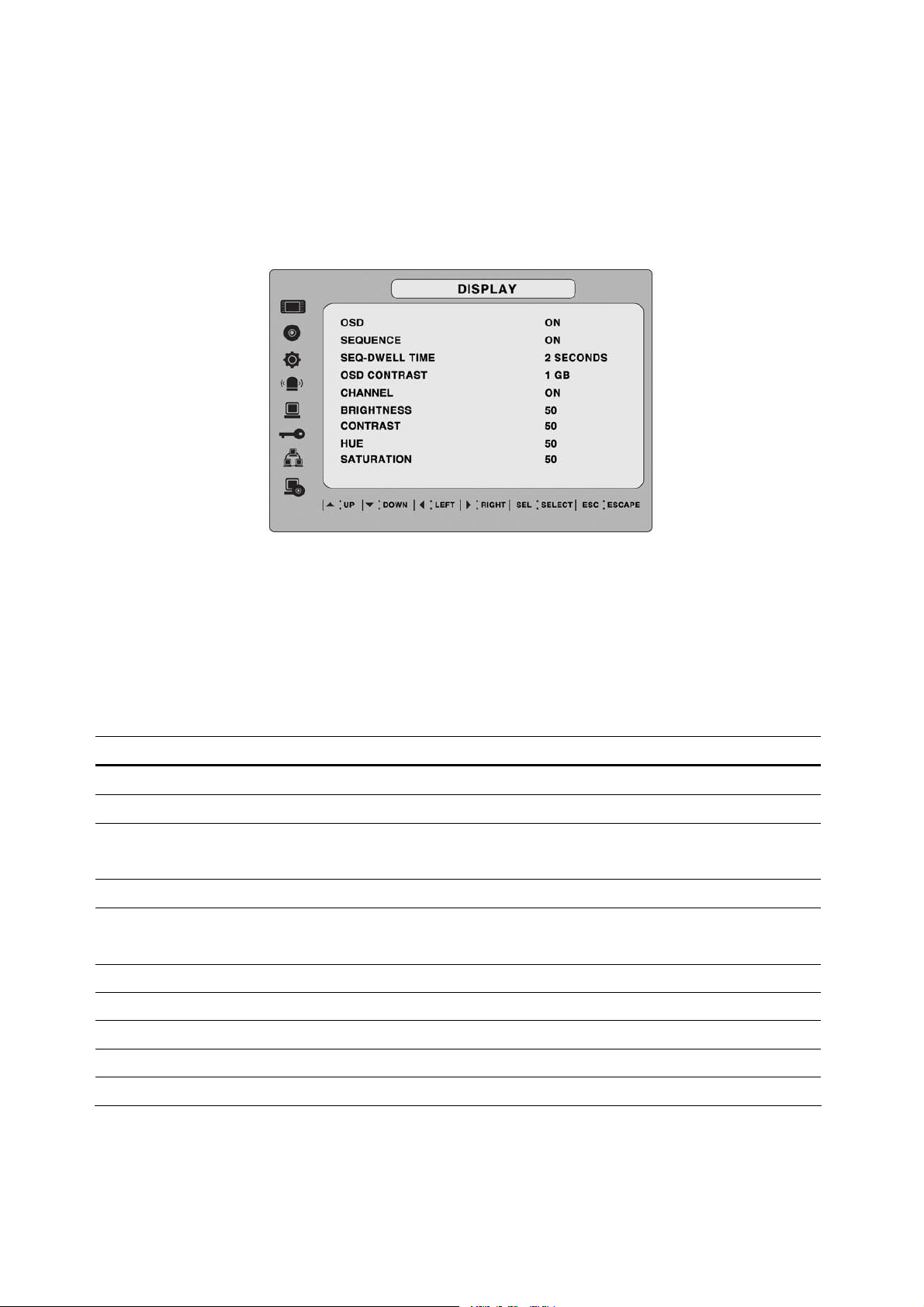
3-2. Setup – Display Mode
To set values for live display, use the UP and DOWN controls to navigate through the menu
items. Change the value of the menu item using the LEFT and RIGHT controls.
Figure 3.2.1. Display mode setup screen
Item Description
OSD
SEQUENCE
SEQ-DWELL TIME
OSD CONTRAST
CHANNEL
DISPLAY
BRIGHTNESS
CONTRAST
HUE
SATURATION
Table 3.2.1. Menu items in DISPLAY mode setup
Enable/disable on-screen-display.
Enable/disable sequential display of video in Full Screen mode.
Set the dwell time for each, 4 or 9 channels display in sequential
display mode.
Set the visibility level of the On Screen Display (OSD).
Select the channel for applying the following settings.
Presses SELECT to change channel name.
Enable/disable display of the video channel in live display mode
Change the brightness value for the specified channel.
Change the contrast value for the specified channel.
Change the hue value for the specified channel.
Change the saturation value for the specified channel.
21
Page 22
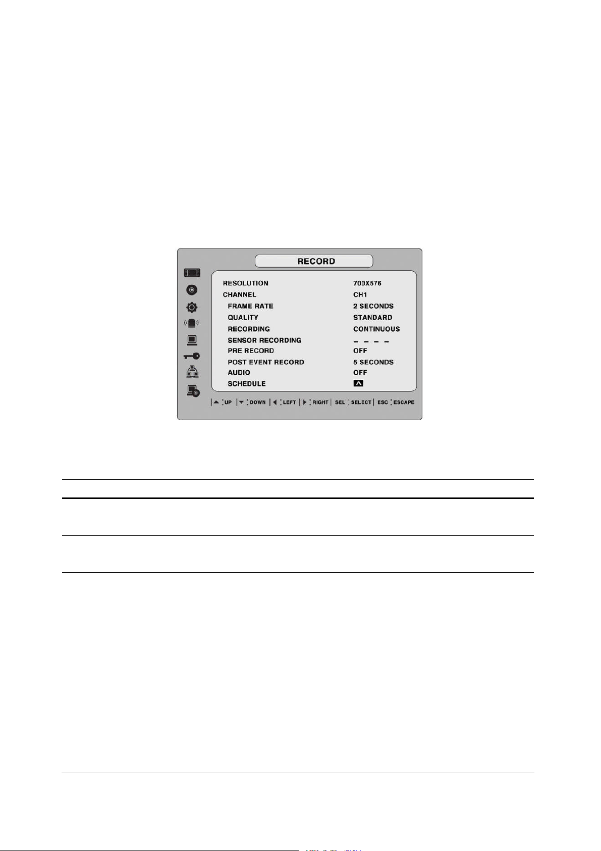
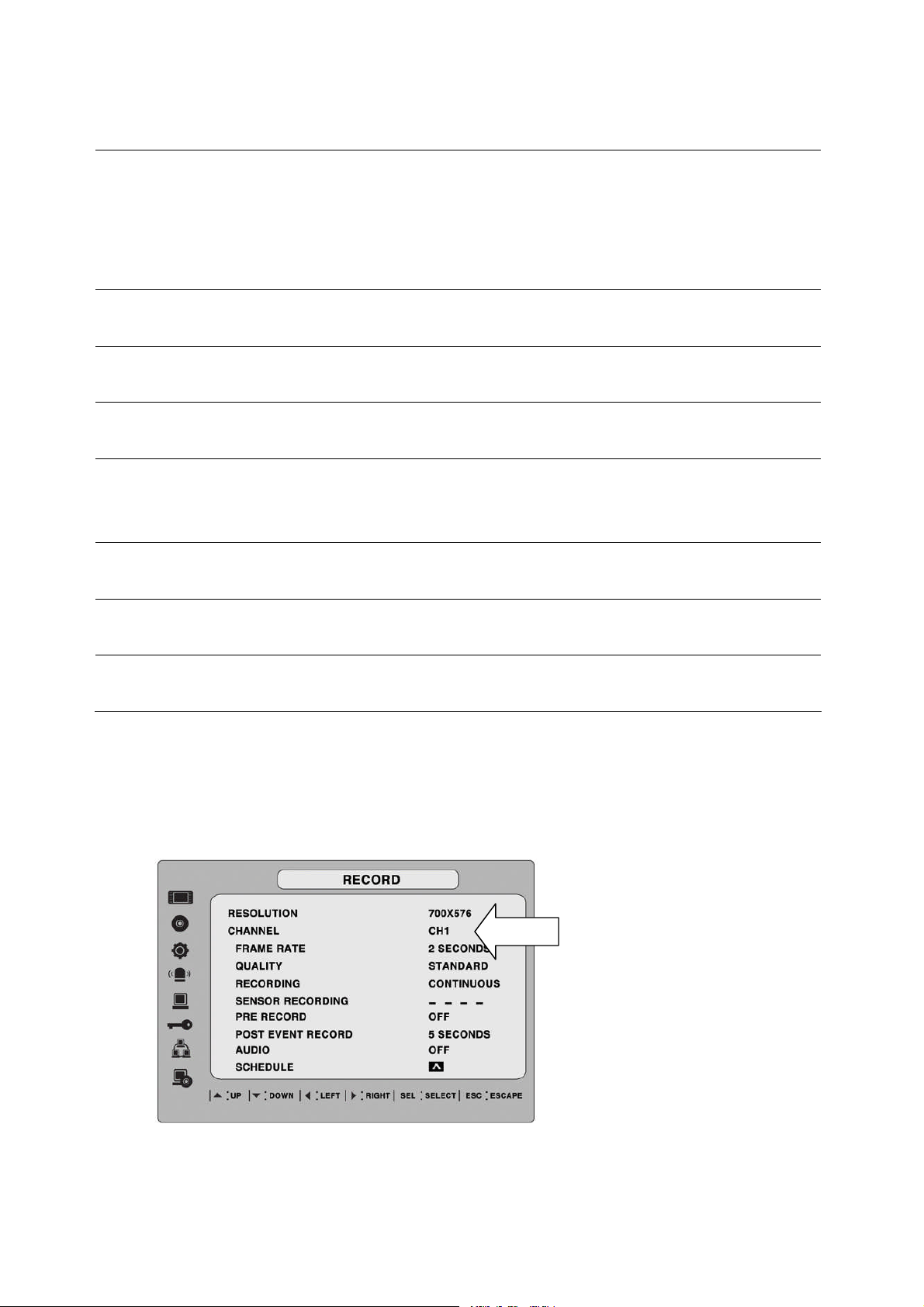
3-3. Setup – Recording Mode
To set values for recording video, use the UP and DOWN controls to navigate through the menu
items. Change the value of the menu item using the LEFT and RIGHT controls.
Figure 3.3.1. Recording mode setup screen
Table 3.3.1. Menu items in Recording mode setup
Menu item Description
RESOLUTION
CHANNEL
FRAME RATE
Set the resolution to either 704x480, 704x240, or 352x240 for
NTSC. (PAL: 704*576/ 704*288/ 352*288)
Select the channel to apply the following settings on. Changes you
make will immediately take effect with the selected channel.
Set the frame rate for the specified channel. The sum of the frame
rate values from each channel cannot exceed the maximum frame
rates for a specific recording resolution.
Typical values of the maximum frame rate for video are
120/100 fps version:
120/100fps: 352*240(NTSC)/352*288(PAL)
60/50fps: 704*240(NTSC)/704*288(PAL)
30/25 fps: 704*480(NTSC)/704*576(PAL)
240/200 fps version:
240/200fps: 352*240(NTSC)/352*288(PAL)
120/100fps: 704*240(NTSC)/704*288(PAL)
22
Page 23
60/50 fps: 704*480(NTSC)/704*576(PAL)
480/400fps version:
480/400fps: 352*240(NTSC)/352*288(PAL)
240/200fps: 704*240(NTSC)/704*288(PAL)
120/100 fps: 704*480(NTSC)/704*576(PAL)
QUALITY
RECORDING
SENSOR
RECORDING
PRE RECORD
POST EVENT
RECORD
AUDIO
SCHEDULE
Select the recording quality for the specified channel. Options are:
Network, Standard, High, Super or Ultra.
Assign the recording mode for each channel. Options are:
Continuous, By Motion, By Sensor, By Schedule or Disable.
Enable setting up to 4 sensors of 9 sensors for the specified
channel.
Enable/disable pre-event recording. Pre-event recording time is 5
seconds and only intra-frames are recorded for pre-event
recording.
Set the post event recording time duration for the specified channel
from 1 to 30 seconds.
Enable/disable audio recording for the specified channel.(Available
from 1CH to 4 CH-Fixed)
Set the recording schedule. This menu item takes you to the
Schedule Setup screen.
3-3-1. Quick record setting
User can setup all the values related with record such as Frame rate, quality, recording type,
Pre-recording, and Post-recording on one page of setup screen.
1. Go to Record>Channel and press SEL button.
2. Then the bellow setup screen will pop up.
23
Page 24
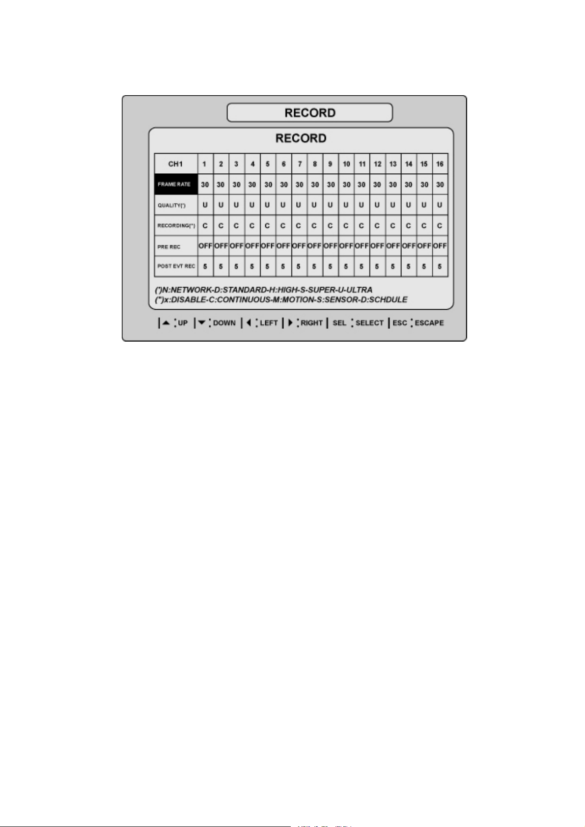
Figure 3.3.2. QUICK RECORD setup screen
3-3-2 Recording Schedules
To set up a recording schedule, select SCHEDULE in the RECORD menu.
Use the arrow buttons to navigate through the items and set the recording.
[ALL]: Selected recording mode using the SEL button is applied to the entire time zone and all
channels.
[SUN to SAT]: Selected recording mode using the SEL button is applied to the entire time zone
for the specified channel.
[Vertical Bar “ | “]: Selected recording mode using the SEL button is applied to the entire
channel for the selected time zone. Each vertical bar “| “corresponds to one hour.
[- Individual Block of Time]: Selected recording mode using the SEL button is applied to the
selected 1-hour increment for the selected channel.
[SEL]: The recording mode can be selected using the SEL button.
[COPY FROM to COPY TO]: Setup values of recording mode for the selected channel can be
copied for another channel setup.
24
Page 25
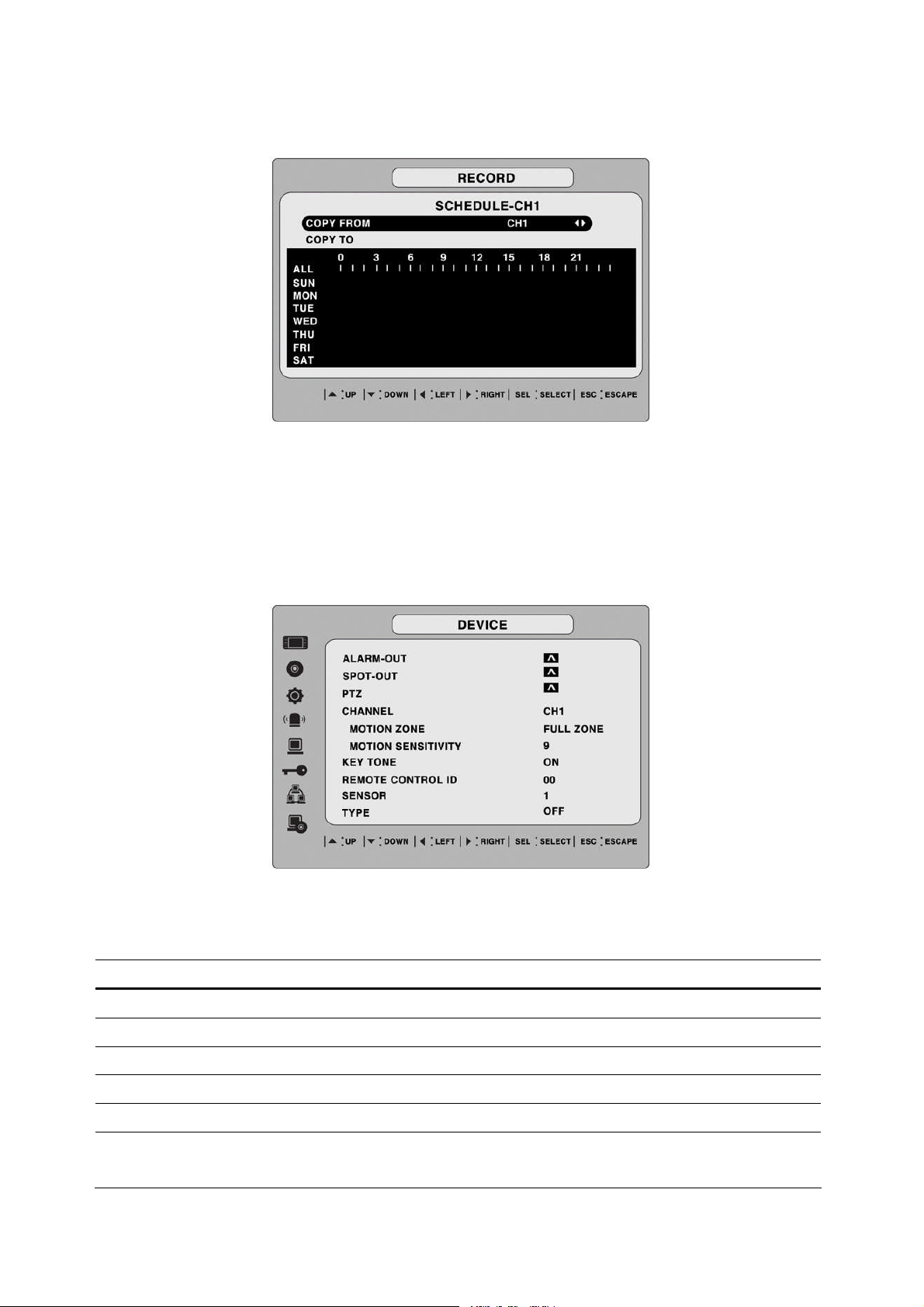
Figure 3.3.2. Schedule recording setup screen
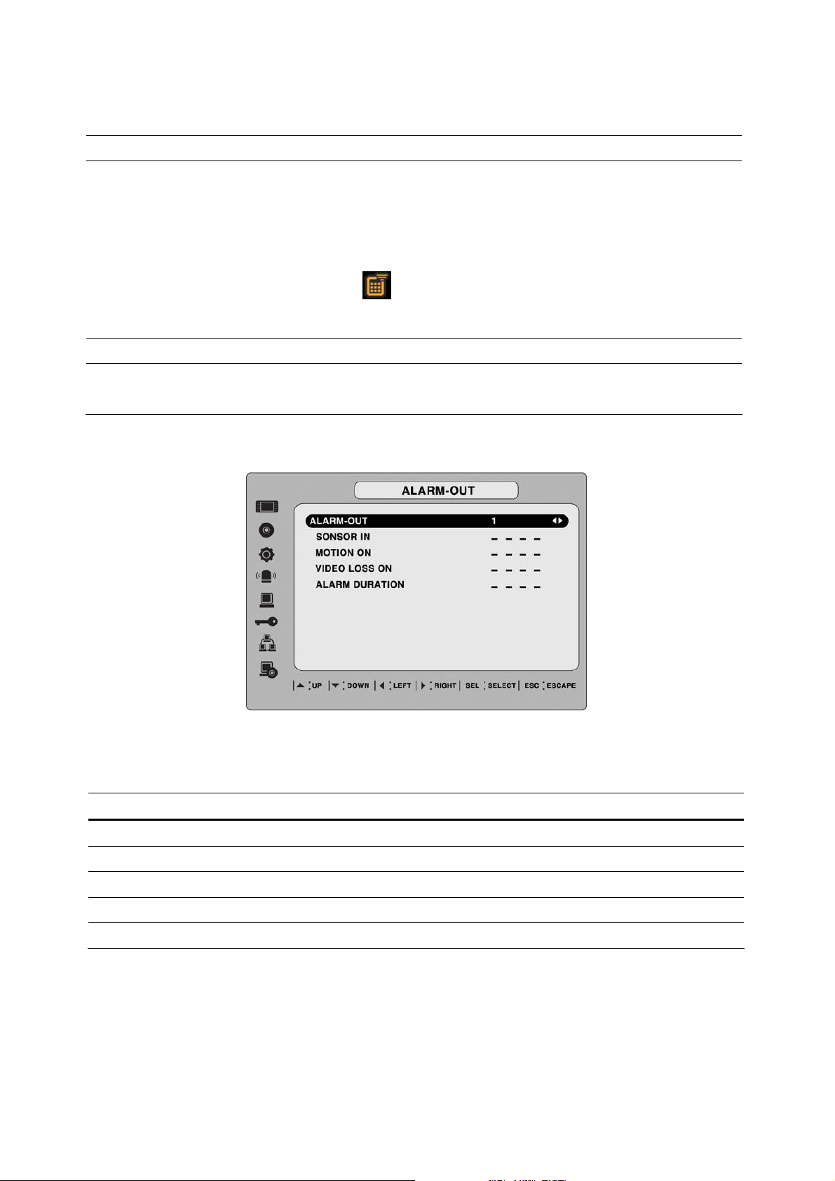
3-4. Setup – Device Mode
To set values for device, use the UP and DOWN controls to navigate through the menu items.
Change the value of the menu item using the LEFT and RIGHT controls.
Figure 3.4.1. Device mode setup screen
Table 3.4.1. Menu items in Device Setup screen
Item Description
ALARM OUT
SPOT-OUT
PTZ
CHANNEL
MOTION ZONE
MOTION SENSITIVITY
Set the sensor, motion, and video loss for each alarm.
Set the all details for spot monitoring.
Set the PTZ camera speed, number, type and ID.
Select specified channel for motion zone setup.
Select Full Zone or Partial Zone for motion sensing.
Set the motion sensitivity for the specified channel.
Control the motion sensitivity from 1 to 9.
25
Page 26
KEY TONE
Enable/disable key tone.
REMOTE CONTROL ID
SENSOR
TYPE
3-4-1. ALARM-OUT
Select an ID of remote control.
1. Select ID.
2. Press the same number as ID set in DVR on a remote
control.
3. Then icon will be displayed on Live screen of DVR
that respond to the remote control.
Select sensor from 1 to 9(16).
Set the type of sensor for the specified channel. Options are:
None, N/O (normal open), and N/C (normal closed).
Table 3.4.2. Menu item in ALARM-OUT Setup screen
Item Description
ALARM OUT
SENSOR IN
MOTION ON
VIDEO LOSS ON
ALARM DURATION
Figure 3.4.2. ALARM-OUT setup screen
Select alarm from 1 to 4.
Enable setting up to 4 sensors of 9/16 sensors for the each alarm.
Enable setting up to 4 cameras of 9/16cameras for the each alarm.
Enable setting up to 4 cameras of 9/16 cameras for the alarm.
Set the dwell time of alarm from1 to 60seconds.
26
Page 27
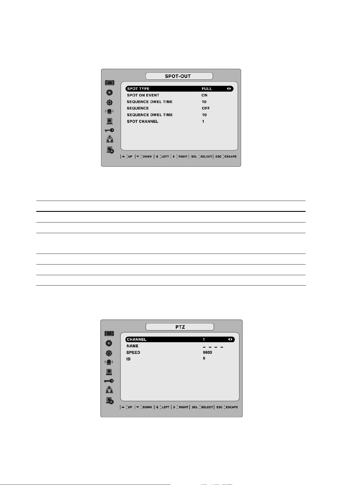
3-4-2. SPOT – OUT
Item Description
Figure 3.4.3. SPOT-OUT setup screen
Table 3.4.3. Menu item in SPOT-OUT Setup screen
SPOT TYPE
SPOT ON EVENT
SPOT EVENT DWELL
TIME
SEQUENCE
SEQ-DWEL TIME
SPOT CHANNEL
Select either FULL or QUAD for spot channel display.
Enable/disable spot channel display when event occurred.
Set the dwell time for the display of the event activated channel.
Enable/disable sequential display of spot channel in full screen.
Set the dwell time for spot channel display in sequential display.
Set the channel for spot monitoring.
3-4-3 PTZ Setup
To control the PTZ functions of the camera, connect the controller to the RS-485 port.
Figure 3.4.4. PTZ Control Setup Screen
27
Page 28

Note: For speed dome cameras that support RS-485, connect them directly to the RS-485 port.
If the camera is controlled with RS-232C, use an RS-485 to RS-232C signal converter.
On the PTZ control Setup screen, you can select or set the protocol type of the camera that is
the same as the one installed on the site. If the camera has a specific camera ID, select the
camera ID using the LEFT and RIGHT arrow controls.
The following options are available on the PTZ control screen.
CHANNEL (channel number that the PTZ is connected to)
NAME (protocol type)
SPEED (19200, 14400, 9600, 4800, 2400)
ID (0-63)
3-4-4. Motion Zone Setup
When you select Partial Zone in the Motion Zone menu, you can set-up the motion sensing
zones in the screen. To move around each rectangular zone, use the arrow controls. Press the
SEL button on each rectangular zone you want to include as part of the motion sensing zone.
As you select each zone, the color changes. Press ESC button to return to the DEVICE menu.
Figure 3.4.5. Motion Zone selection screen
28
Page 29
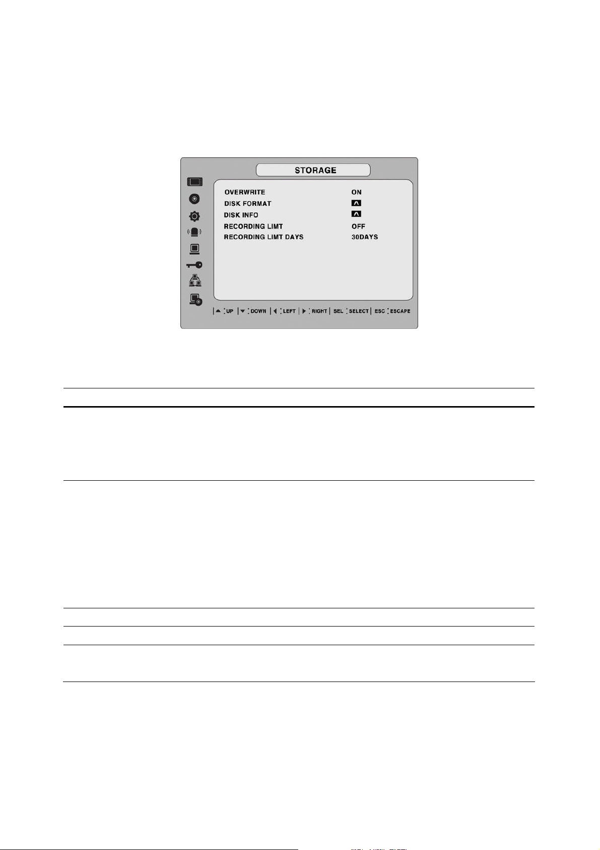
3-5. Setup – Storage Mode
Set the storage parameters in the Storage setup screen.
Figure 3.5.1. STORAGE setup screen
Table 3.5.1. Menu items in STORAGE Setup screen
Item Description
OVERWRITE
DISK FORMAT
DISK INFO
RECORDING LIMIT
RECORDING LIMIT DAYS
When enabled, the DVR will continue recording and
overwrite the oldest existing recorded data once the hard
drive is full. When disabled, recording will stop once the hard
drive is full.
Format the hard drive. Use the UP and DOWN arrow buttons
to select ON, then press SEL. You then have the option to
YES or NO.
Caution
All recorder data will be lost. We recommend that you
archive any data that you may need in the future before you
format the hard drive.
Hard drive information
Enable/disable recording limit.
Set the limit days for recording to the hard disk drive from 1
to 60 days.
29
Page 30
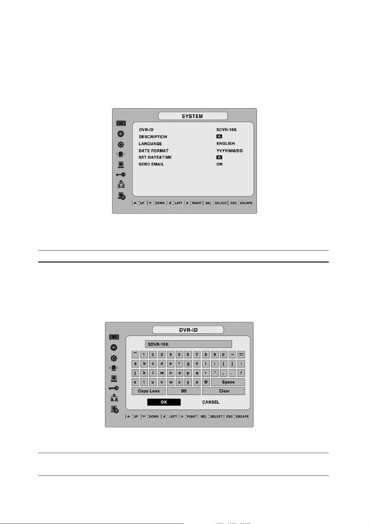
3-6. Setup – System Mode
Use the System Setup screen to input system parameters.
Use the UP and DOWN arrow controls to navigate through the menu items and use the LEFT
and RIGHT arrow controls to change the value of the menu items.
Figure 3.6.1. SYSTEM Setup Screen
Table 3.6.1. Menu items in SYSTEM Setup screen
Item Description
DVR ID
Set the name of the DVR.
Press the SEL button, use the LEFT and RIGHT or UP and DOWN arrow
controls to navigate through the position for each alphanumeric character
and Press SEL to apply the selected character. And Press OK to confirm
the name.
SPACE / Caps Lock(Select either Capital or Lower letter)
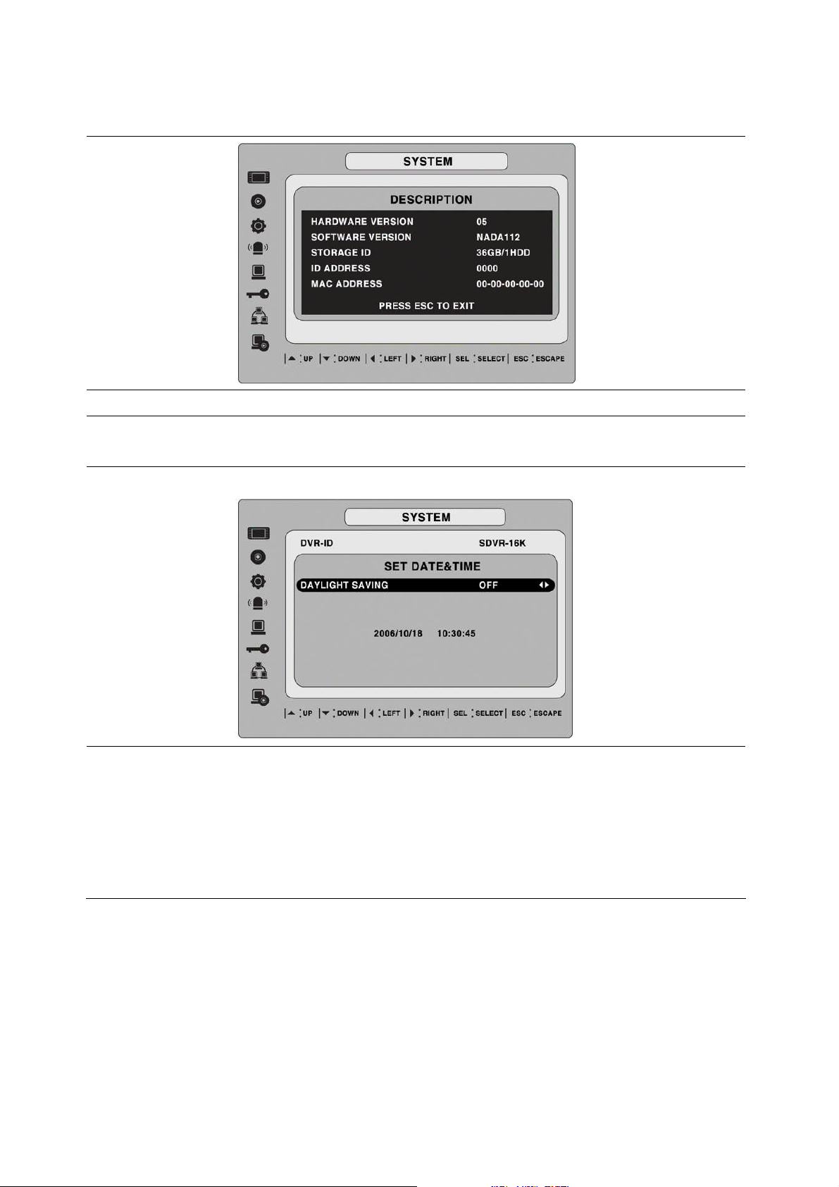
DESCRIPTION
BS(Back space: Erase previous character) / Clear(Erase all characters)
Press SEL to view system information.
(System version, storage capacity, IP address and MAC address.)
30
Page 31
LANGUAGE
Set the desired language.
DATE FORMAT
SET DATE&TIME
Set the desired date and time display format. Options are:
YYYY/MM/DD MM-DD-YYYY DD-MM-YYYY
Set the present date, time and daylight saving for the DVR.
DATE & TIME
Set the present date and time for the DVR. Press SEL, then use the
LEFT and RIGHT arrow controls to navigate through the position of each
alphanumeric character in the date and time. Use the UP and DOWN
arrow controls to change the selected character. Press ESC and select
YES to confirm the new date and time.
31
Page 32
DAY LIGHT SAVING
Set the DLS (Daylight Saving) for the area.
The options are:
USA
EU
Others
OFF.
1. USA (DLS time is applied automatically when being on the DLS
time zone and is displayed on the current time)
2. EU (Set the GMT area for DLS time apply on the current time)
- GMTAREA +00:00
3. OTHERS
- BEGIN (MAR/1ST/SUN/00H)
- END (SEP/1ST/MON/00H)
(Set the BEGIN and END time for the specific area except EU and USA)
use the UP and DOWN arrow controls to change the value of month,
week, day and hour.
CAUTION:
-Do not set the start time to 23:00 for DLS.
-DLS can’t be applied, if the date of BEGIN and END is same.
32
Page 33
3-7. Setup – PASSWORD Mode
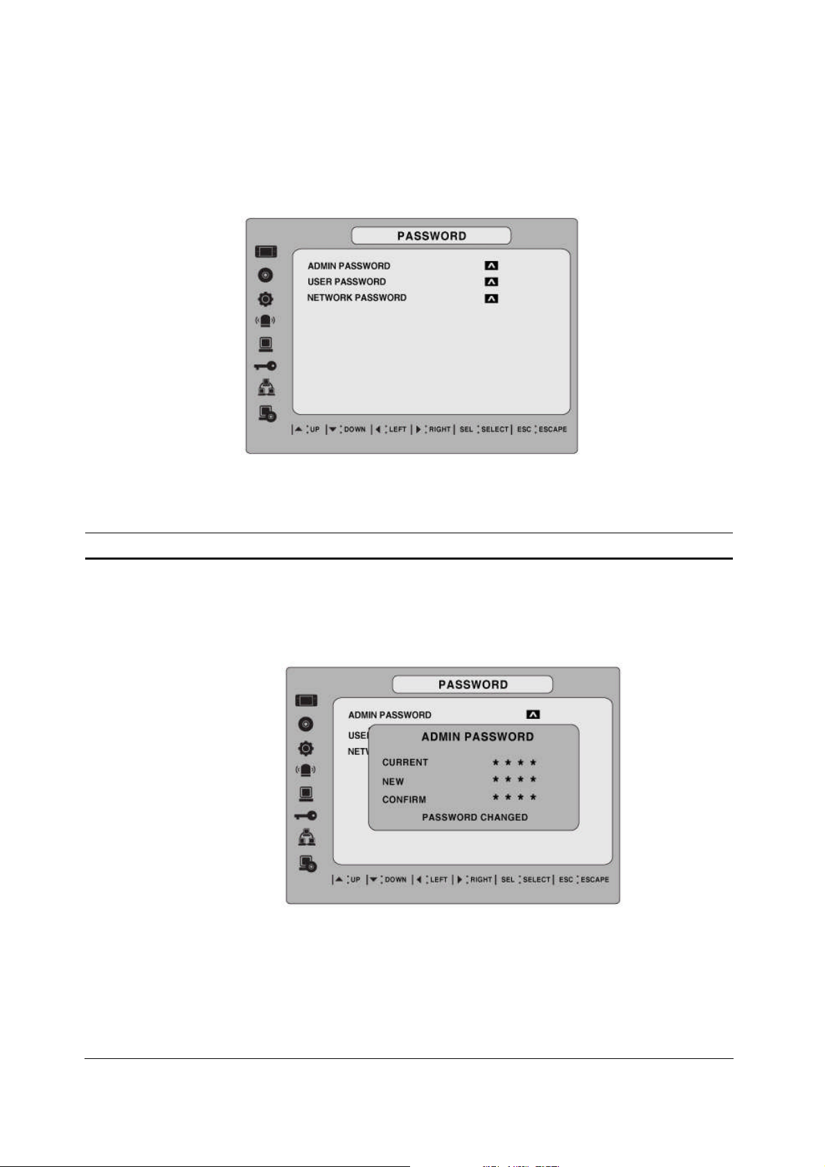
Use the LEFT or RIGHT and UP and DOWN arrow controls to set the password.
Figure 3.7.1. PASSWORD setup screen
Table 3.7.1. Menu Items in PASSWRORD Setup Screen
Item Description
ADMIN PASSWORD
Set the administrator password. After selecting this menu item
you will be promoted for your current password and then the new
password. Follow the prompts to change and confirm the new
password.
The default password is 1111.
Use the arrow controls to change the password.
UP=1
RIGHT=2
DOWN=3
LEFT=4
33
Page 34

Admin password is asked for the following functions.
Setup, Power, Search, and Key Lock from remote control.
USER PASSWORD
NETWORK PASSWORD
Set the user password. After selecting this menu item you will be
promoted for your current password and then the new password.
Follow the prompts to change and confirm the new password.
The default password is 1111.
Use the arrow controls to change the password as described in
ADMIN PASSWORD above.
User password is asked for the Search function.
Set the remote access password. You will need to enter this
password when connecting to this DVR through the client
software program. After selecting this menu item you will be
prompted for your current password (the default password is
1111) and then the new password. Follow the prompts to change
and confirm the new password. Use the arrow controls to change
the password as described in ADMIN PASSWORD above.
34
Page 35
3-8. Setup – Network Mode
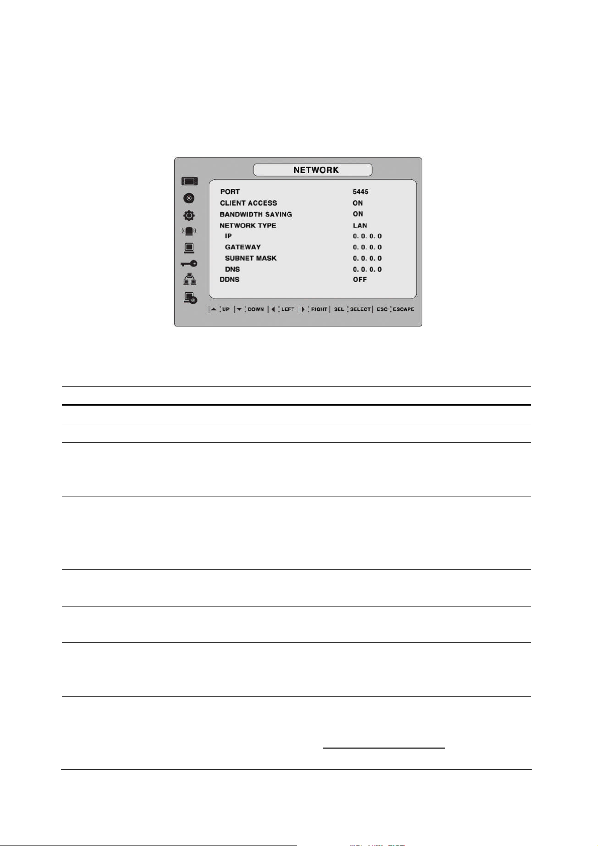
Set up your network parameters on the Network Setup screen.
Figure 3.8.1. NETWORK setup screen
Table 3.8.1. Menu items in Network Setup screen
Item Description
PORT
CLIENT ACCESS
BANDWIDTH SAVING
NETWORK TYPE
DHCP
ADSL (PPPoE)
LAN
DDNS
Port number (Default: 5445)
Enable/Disable remote access through client software.
Enable/Disable only key frame transmission. “ON” mode is
favorable for use of low network bandwidth. Mostly, set “OFF” for
normal use.
Set the type of network connection. Options are:
LAN, DHCP, ADSL
Note. Other parts of the Network Setup screen change depending
on what network type you select.
Sets to use HDCP (If this is selected, DVR automatically get IP
varying from time to time from network.)
ID: Registered ID is necessary for ADSL connection.
Password: Registered password is necessary for ADSL connection.
IP: Register IP address that is assigned for DVR.
Gateway: Register Gateway that is assigned for DVR.
Subnet Mask: Register Subnet Mask that is assigned for DVR.
Enable/disable using domain name address through DDNS server.
“ON”mode, DDNS server name appears for domain registration.
The DDNS sever name is ns.standalone4ch.com.
CAUTION: Do not change this sever name. If this is changed, the
35
Page 36
DDNS service cannot be used.
Registration
Check the MAC address of DVR from Setup>System>Description.
Please contact a distributor or an installer to register your DVR on a
DDNS Server. Register the domain name on DDNS Server.
After the domain name and MAC address of the DVR are registered
on a DDNS server, user can access the network with their own
domain name.
3-8-1. Ports
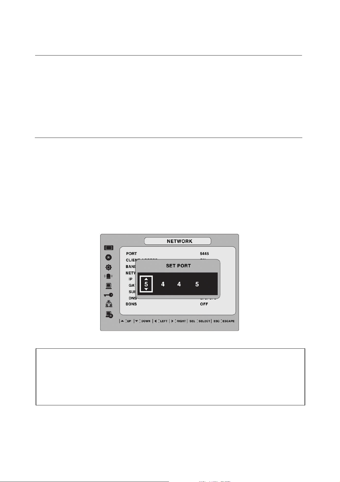
When you connect one or more DVRs to a network through an IP sharing device, each device
must have a unique TCP port number for access to each unit from outside the LAN. Also, the IP
sharing device must be configured for port forwarding so when each port is accessed on the IP
sharing device, it will forward to the appropriate DVR.
Note: This port number is listed next to the Port menu option in the Network Setup screen. If
you plan to access the DVR units only from within the same LAN, the TCP port does not have to
be changed.
Figure 3.8.1. Network setup screen - PORT
Network access beyond a router
In order to access the DVR remotely beyond a router (firewall), the user must open one TCP
port for command level, live channels and storage channels. If this port is not opened
properly, user can not access DVR beyond a router.
If the DVR port number is set to 5445, open the TCP port 5445 on the router.
36
Page 37
3-8-2. Network Types
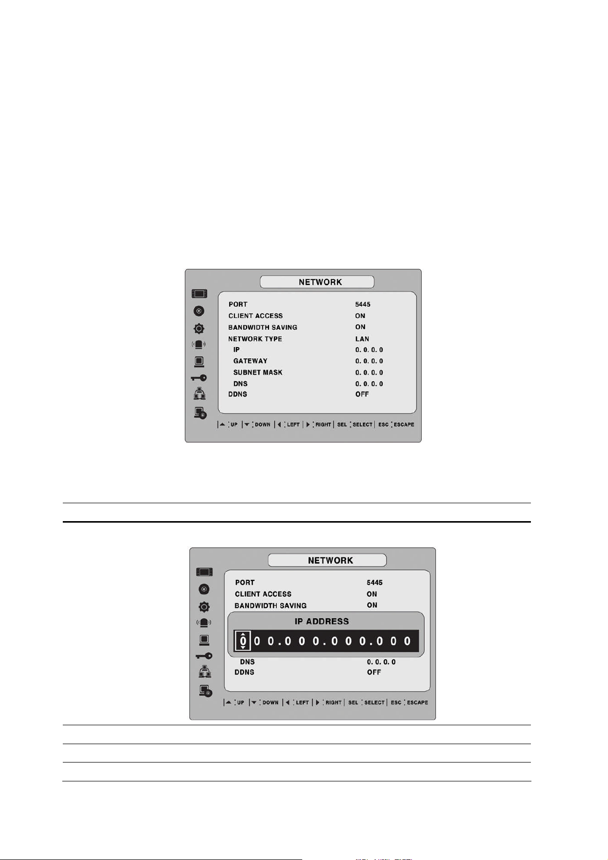
3-8-2-1. LAN
1. for the use of fixed IP. (See your network administrator if you do not have this
information.)
2. When DVR is installed in IP sharer that is connected with ADSL, a user can assign fixed
IP to DVR from IP sharer itself using “DMZ”function out of such sharer.
Input IP set in DMZ on “IP”field and Gateway of ADSL modem on “Gateway”field. Similarly,
for Subnet Mask, DNS address, input relevant values in IP sharer.
Figure 3.8.2. Network setup screen - LAN
Table 3.8.2. LAN
Item Description
IP
GATEWAY
The fixed IP address of the DVR unit
The IP address of the Gateway
SUBNET MASK
DNS
The subnet mask for the LAN
The address for the DNS server
37
Page 38
3-8-2-2. DHCP
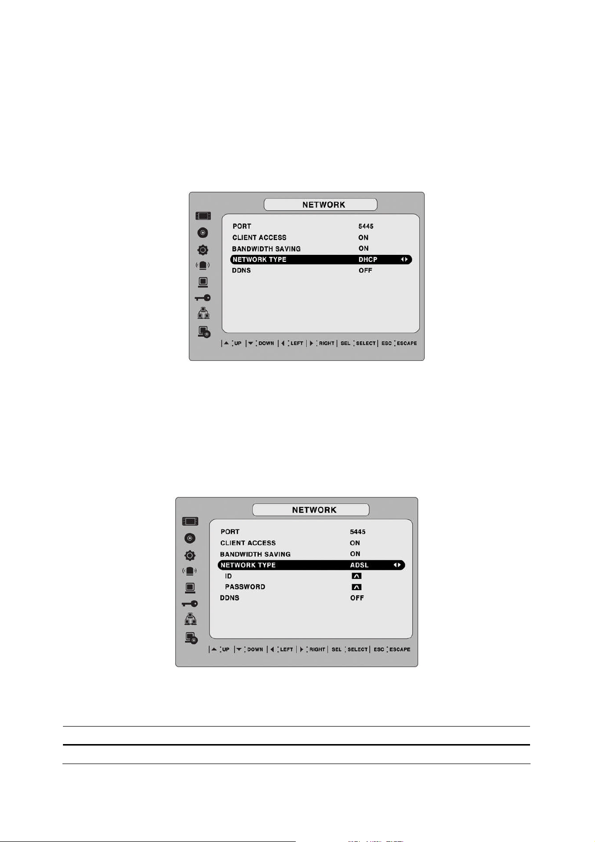
An IP address is automatically assigned by the DHCP server, which automatically assigns IP
address and other parameters to new devices.
When ADSL or other network being used adopts variable IP method, not fixed IP. This option is
used as a way to automatically get IP address.
Figure 3.8.3. Network setup screen - DHCP
3-8-2-3. ADSL (PPPoE)
To use this ADSL (PPPoE) function when the network type connecting the DVR is using PPPoE
method.
If ADSL type is not using inputting IP and Password like VDSL or DVR is installed in IP sharer, a
user can not select this function. In this case, a user should select DHCP or LAN.
Figure 3.8.4. Network setup screen - ADSL
Table 3.8.3. ADSL
Item Description
ID
The user ID for the ADSL connection
38
Page 39
PASSWORD
The password for the ADSL connection
3-8-3. Saving Setup of Network setup
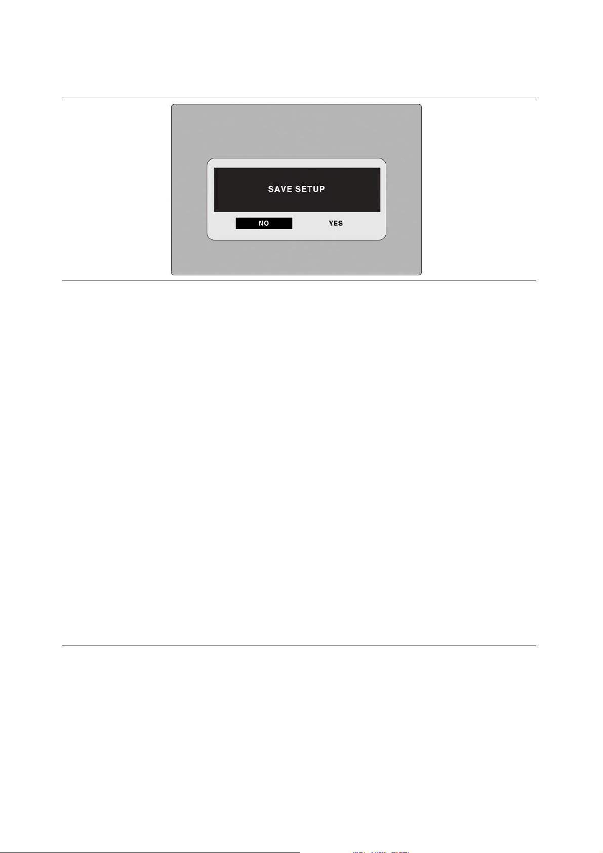
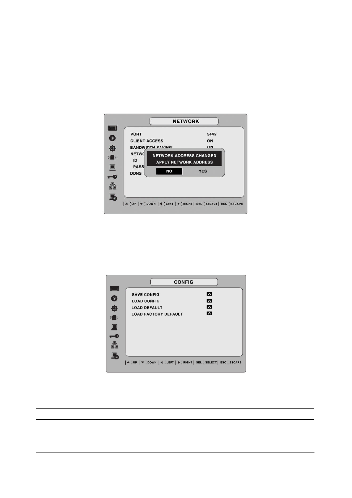
After changing the network configuration, confirmation window will popup. To preserve the setup
values that you have selected, select YES. Then system will reboot.
Figure 3.8.5. Network setup screen – SAVE SETUP
3-9. Setup - CONFIG Mode
User can control the configuration of DVR.
Figure 3.9.1. Config setup screen
Table 3.9.1. config setup
Item Description
SAVE
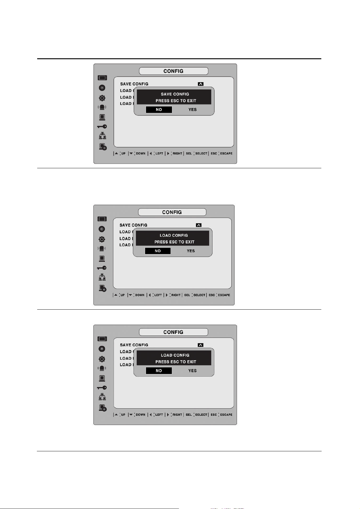
User can save the current configuration (Setting values) of DVR to the USB
CONFIG
memory stick. Put the USB stick on the front panel and press SEL to start
the saving process.
39
Page 40
LOAD
User can upload the configuration of DVR to another DVR using the USB
CONFIG
LOAD
DEFAULT
Memory stick. Put the USB stick on the front panel and press SEL to start
the loading process.
Select ON to reset the system to the default settings.
(Password, date format, DLS, Network setting, and HDD Overwrite will
not be included.)
40
Page 41
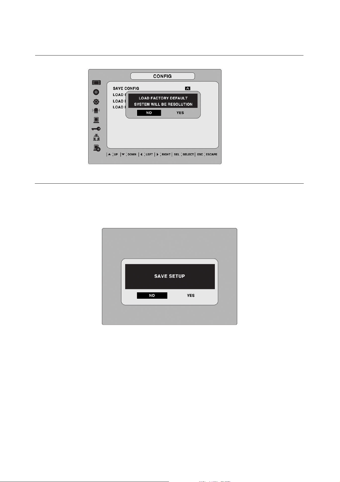
LOAD
FACTORY
DEFAULT
Select ON to reset the system to the factory default settings.
4. Saving Setup
To preserve the setup values that you have selected, select YES.
Figure 4.1.1. SAVE SETUP screen
41
Page 42
5. Live, Search, and Playback
5-1. Live Viewing Screen
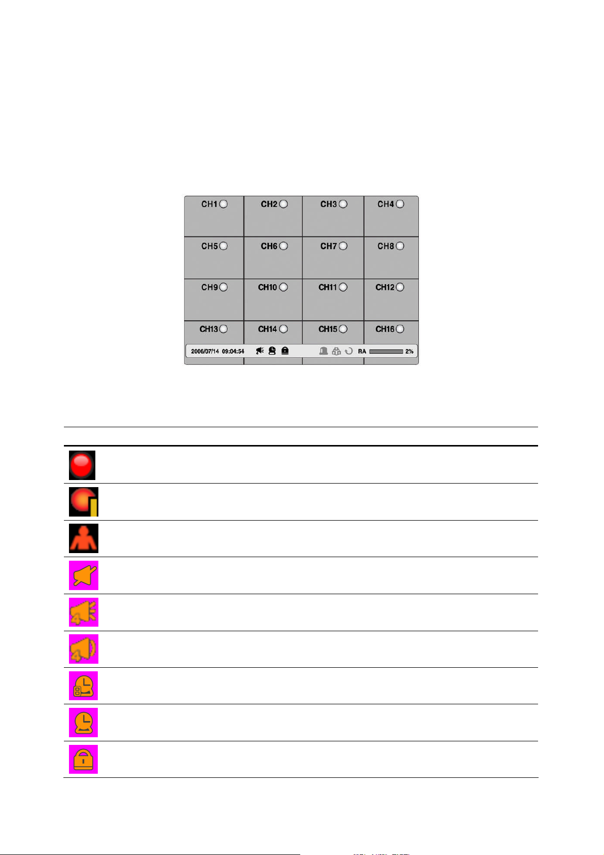
In the Live screen, video inputs from the cameras are displayed as they are configured in the
Display Setup screen. Various on-screen display (OSD) symbols, which indicate the status of
the DVR, are described in Table 5.1.1.
Figure 5.1.1. Live Viewing Screen
Table 5.1.1. Status Indicator Icons in Live Viewing Screen
Icon Description
Continuous recording in progress.
Manual recording in progress. To set the Manual recording mode, press the Record
button on the front panel.
Motion alarm recording in progress.
Audio mute. To set audio mute, press the Audio button on the front panel.
Single audio display. To set audio single for highlighted channel only, press the Audio
button on the front panel.
Mixed audio display
Indicates that alarm is set. To set the alarm function, press the Alarm button on the
front panel.
Indicates that alarm output is activated.
Indicates that lock function for a remote control is set.
42
Page 43
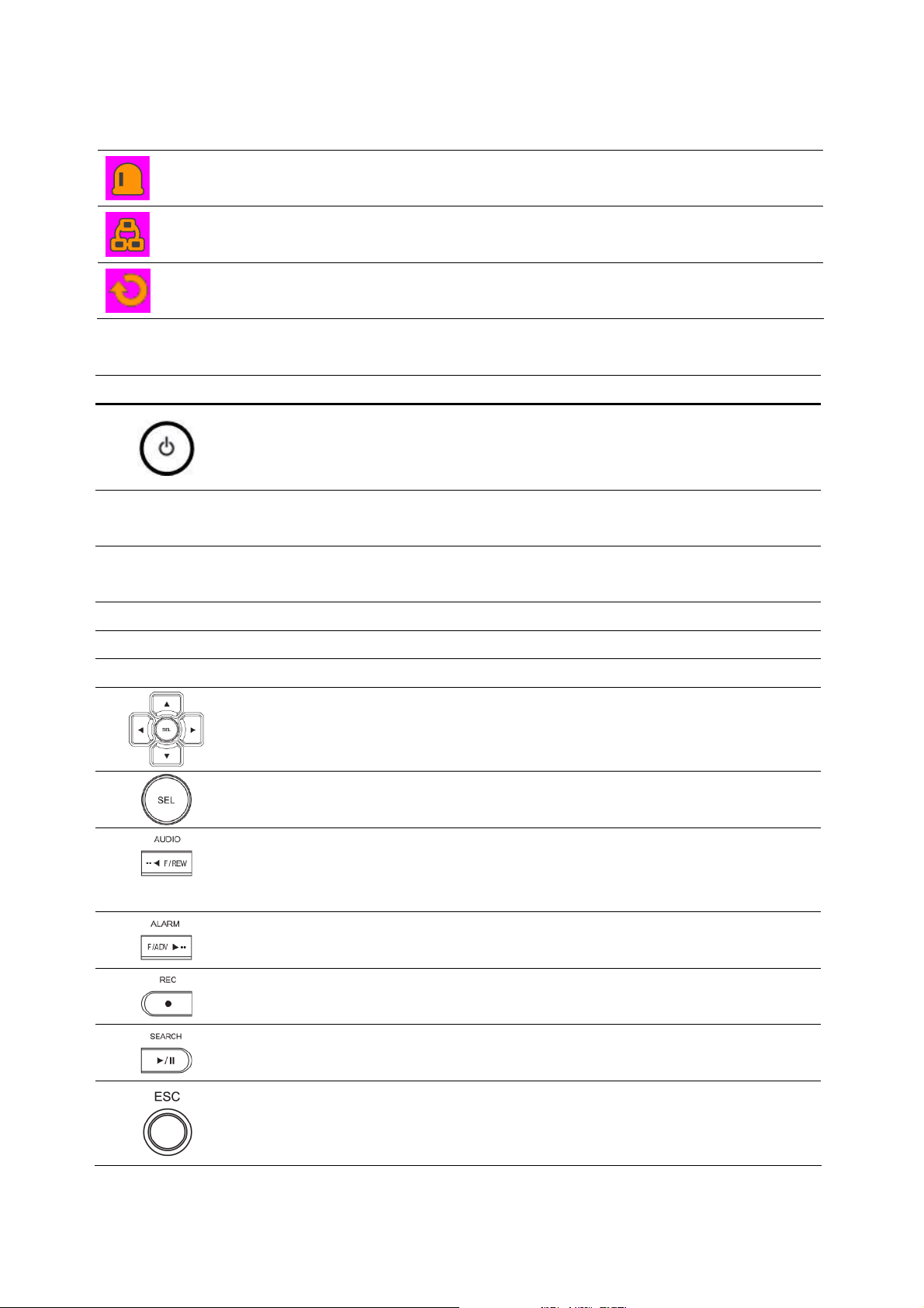
Alarm indicator. When there is an alarm (sensor or motion alarm) in the video
channel, this icon will be highlighted bright red.
Indicates that a network client is connected to the DVR.
Indicates that sequencing mode is enabled.
Table 5.1.2. Button functions in Live Viewing Screen
Button Description
POWER ON/ OFF. If a password is set for power off, the system will ask for
the password when the power button is pressed.
CHANNEL
0~9
SEQ
PTZ
SETUP
BACKUP
Channel keys. For channel 10, press the 0 key. For channel 11, press the
+10 and 1 key. For channel 16, press the +10 and 6 key.
Enable/disable the automatic sequential display of channels in full screen,
quad, 9-split display mode.
Controls Pan/Tilt/Zoom operations.
Launch the SETUP menu.
Press to capture video in jpeg format.
Use the arrow controls when you want to move to next or previous channel
and for number use when entering password.
UP=1, RIGHT=2, DOWN=3, LEFT=4
Switch between full, quad, 9 split and 16 split screen.
Press to select audio mode such as SINGLE, MIX and MUTE.
MUTE- All of 4 channels. SINGLE- Highlighted channel only.
MIX- All of 4 channels.
Enable/disable alarm operation.
Perform continuous or manual recording for all channels.
To enter into the SEARCH menu.
To exit from each menu.
43
Page 44
5-2. SEARCH Screen
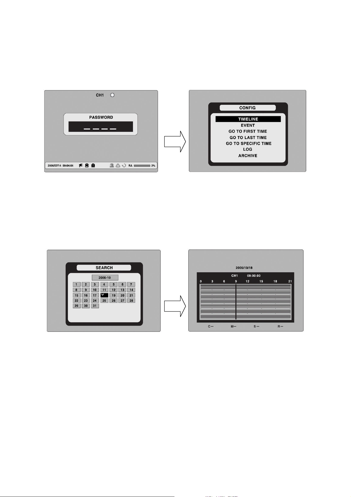
Press SEARCH in live mode to enter the Search screen.
When you press the Search button, DVR asks for a password as in Figure 5-2-1.
Figure 5.2.1. Search Screen
Enter the password using the arrow controls.
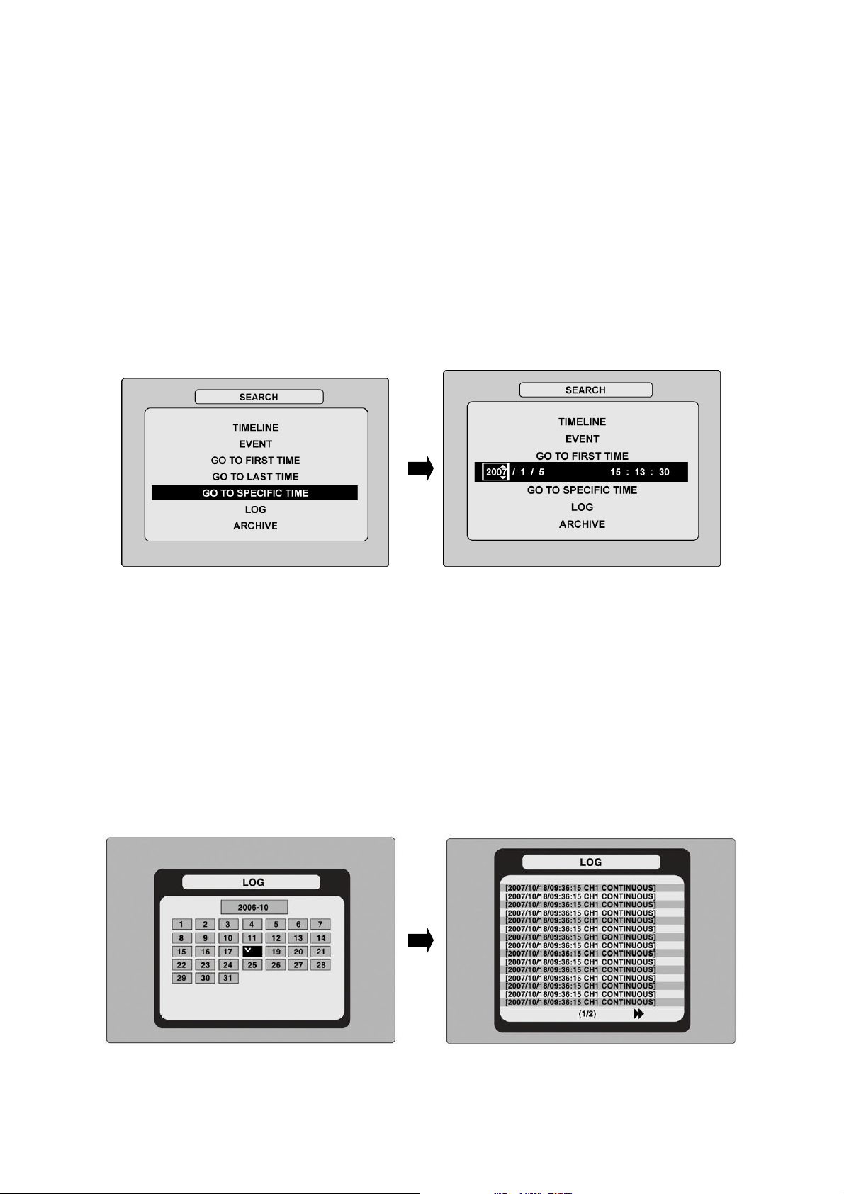
There are 7 ways of search menu such as TIMELINE, EVENT, GO TO FIRST TIME, GO TO
LAST TIME, GO TO SPECIFIC TIME, LOG, and ARCHIVE on the screen.
5-2-1. TIME-LINE Search
The TIME-LINE search window is used to find the stored video by using the time line bar.
Figure 5.2.2. Time-line Search
1. Select the date of the video to begin searching by using the LEFT, RIGHT, UP and DOWN
buttons to navigate through the days.
2. Once you have selected the date, press the SEL button to move to the time line search
window.
3. Use LEFT / F/ADV or RIGHT/ F/REW buttons to select a time zone on the 24 hours time
table.
: The recording mode is indicated on the screen as below.
Note
C: Continuous-Green
M: Motion-Yellow
S: Sensor-Red
R: Manual -Purple
44
Page 45
4. Once you have selected the time zone, press the SEL button to move to the 60 minutes
time table.
5. Select All or a specific channel to search by using the UP and DOWN arrow buttons.
6. Once you select the channel, use the LEFT / F/ADV or RIGHT/ F/REW arrow buttons to
move the time line select bar (blue) to the point you wish to start playing the video clip.
7. Press the SEL button to playback the recorded video.
5-2-2. Event Search
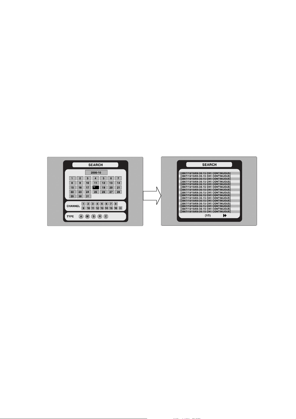
The Event Search window is used to find stored video. Three categories of search filters can
be applied: DATE, CHANNEL and TYPE. Press SEL to select a value and move down to the
next category and use the UP arrow button to move up to the categories you have
previously entered. The ESC button will return the user to the previous screen.
Figure 5.2.3. Event Search screen
1. Select the date of the video to begin searching. Use the LEFT, RIGHT, UP, and DOWN
buttons to navigate through the days.
2. Once you have selected the date, press SEL to move to the CHANNEL selector.
3. Use LEFT and RIGHT buttons to change the channel selection from ALL to any of the
available channels.
4. Once you have selected the channel, press SEL to move to the TYPE selector.
5. Use the LEFT and RIGHT buttons to change the type of recording to ALL, MOTION,
SENSOR, MANUAL, or CONTINUOUS.
6. Once you have selected the type of recording to search for, press SEL to produce a list
of instances that fit your search criteria.
7. Use the UP and DOWN buttons to scroll through the on-screen listings.
8. Use the LEFT and RIGHT buttons to display a list of events that happened previous to or
after the current selection.
9. Once the desired event has been selected, press SEL to start playing back the selected
video.
10. Press the BACKUP button to launch the archiving function in playback mode.
45
Page 46
5-2-3. Go To First Time
You can access the oldest recorded data on the DVR hard drive by selecting GO TO FIRST
TIME on the SEARCH window.
5-2-4. Go To Last Time
You can access the latest recorded data on the DVR hard drive by selecting GO TO LAST
TME on the SEARCH window.
5-2-5. Go To Specific Time
Figure 5.2.4. Go To Search Screen
You can search for video data from a specific instance by setting the date and time in the
GO TO search window. Use the LEFT or RIGHT arrow buttons to move through the date
and time values in this menu. Use the UP and DOWN arrow buttons to change the date and
time value. Press SEL when the appropriate date and time is entered to playback the
recorded video.
5-2-6. Log List Search
You can access the LOG list search screen by selecting LOG on the SEARCH window.
Select a date and press SEL to open the LOG list from that date.
Figure 5.2.5. Log Search Screen
46
Page 47
5-2-7. Archive Search
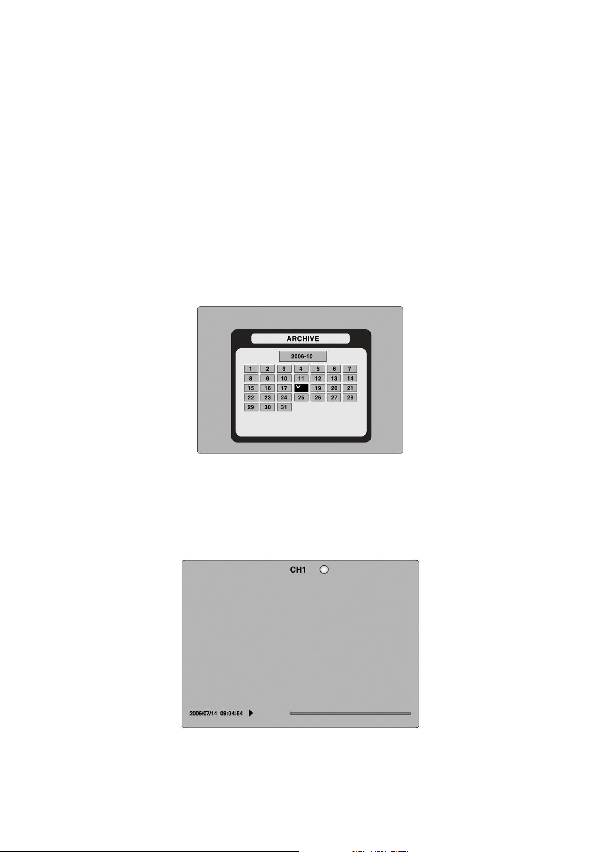
The ARCHIVE Search window is used to find previously stored video or images.
1. Select the date to begin searching by using the LEFT, RIGHT, UP and DOWN buttons to
navigate through the days.
2. Once you have selected the date, press SEL to open the list of stored data.
3. Use the UP and DOWN buttons to scroll through the on-screen listings.
4. Use the LEFT and RIGHT buttons to display a list of stored events that happened
previous to or after the current selection.
5. Once the desired event has been selected, press SEL to view the still image or the first
frame of the selected video.
6. Press the BACKUP button to launch the archiving function in playback mode.
Figure 5.2.6. Archive Search Screen
5-3. Play mode
During playback of a recorded event, the mode changes from SEARCH to PLAY. While in PLAY
mode, you may return to the SEARCH screen by pressing the ESC button.
Figure 5.3.1. PLAY Mode Screen
47
Page 48
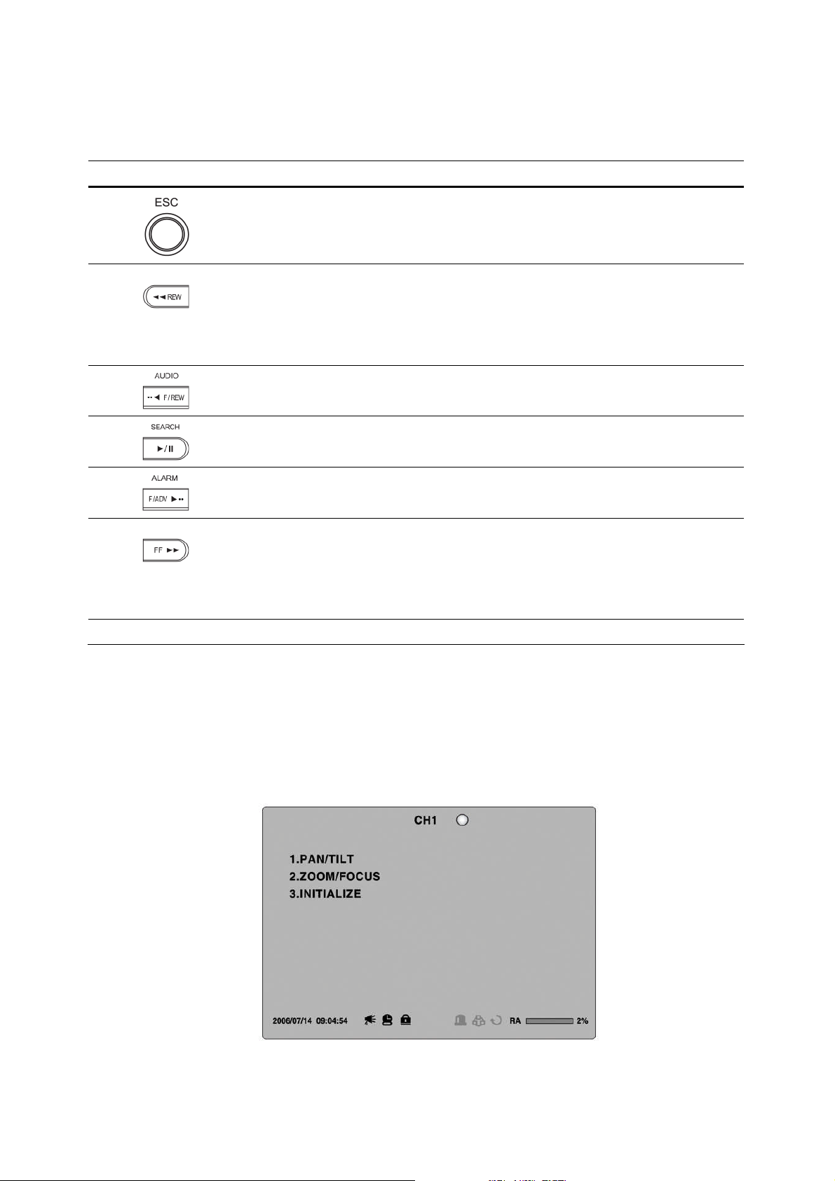
Table 5.3.1. Button functions in PLAY Mode
Button Description
Return to the previous menu screen, search window, or exit from the
menu
Press to rewind the footage at 1x, 2x, 4x, and 8x speeds. Reverse
playback speed is shown as -1x(normal), -2x (2 times normal), -4x (4
times normal), and -8x (8 times normal) at the bottom right of the
screen.
Jump/Step backward.
The playback position moves 60 seconds backward.
Press to play or pause recorded video.
Jump/Stepforward. Playback position moves 60 seconds forward.
Press to fast forward the footage at 1x, 2x, 4x, and 8x speeds.
Playback speed is indicated as +1x, +2x, +4x, and +8x for normal,
twice, 4 times, and 8 times of the regular speed at the bottom right of
the screen.
BACKUP
Press to launch the archiving function.
6. PTZ Control
To control the PTZ functions of the camera, press the PTZ button on the front panel.
Select the item you wish to control the PTZ camera and control them by using the UP and
DOWN or LEFT and RIGHT buttons. Please refer to the table 6.1.1. for the control.
Figure 6.1.1. PTZ Control Screen
48
Page 49
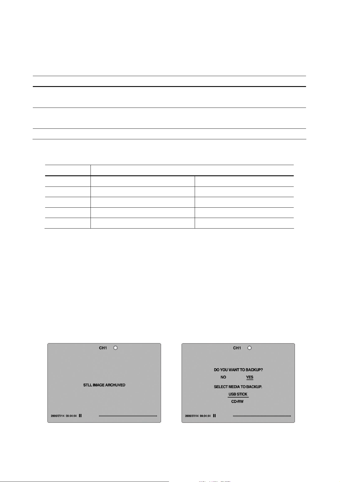
Table 6.1.1. Button Functions in PTZ Control
Item Description
PAN / TILT
ZOOM / FOCUS
INITIALIZE
NO. Description
Classification Rs-422 RS-485
1 TX+ (+ Transmit data)
2 TX- (- Transmit data)
3 RX+ (+ Receive data) Data +
4 RX- (- Receive data) Data -
Use the UP or DOWN button for TILT and LEFT or RIGHT button for PAN of
the selected camera.
Use the UP or DOWN button for ZOOM in or out and LEFT or RIGHT
button for FOCUS near or far of the selected camera.
Initialize the PTZ settings of the selected camera.
Table 6.1.2. Description of RS-422/485 port
7. Backup
7-1. Still Image backup onto USB flash memory or CD media
Still images can be captured and archived onto the USB stick, CD media or hard drive in live
mode or while playing back recorded video.
In live mode, press the BACKUP button to launch the archive function.
1. When you press BACKUP button, the archiving screen will display as Figure 7.1.1.
2. And the DVR will ask which media you will take for archiving.
3. Once you select the media, the system will start to archive the data to the selected
media.
Figure 7.1.1. Still Image Archiving and Backup Screen
49
Page 50
7-2. Video backup onto USB flash memory or CD media
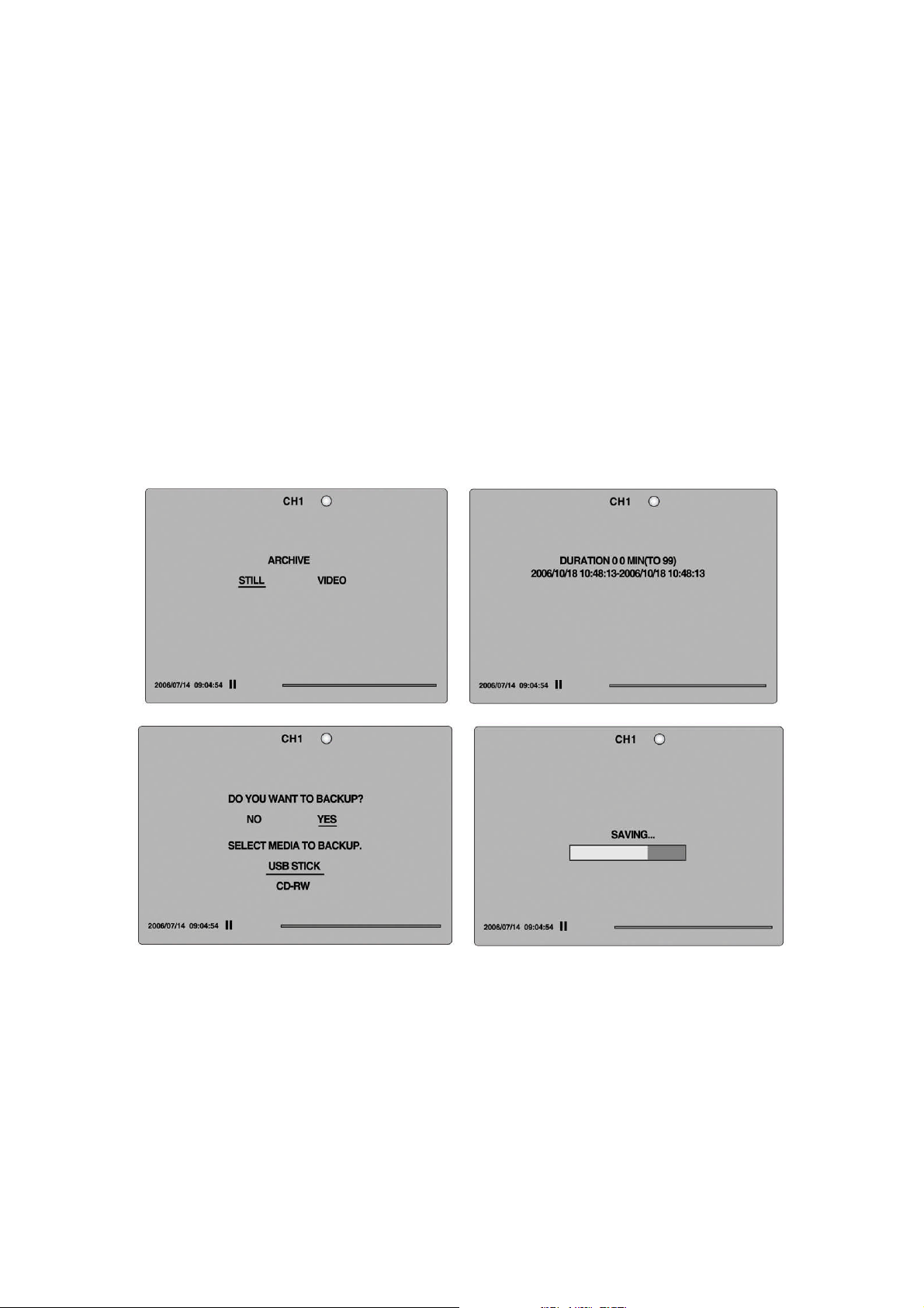
Video can be captured and archived onto the USB stick, CD media or hard drive while playing
back recorded video.
In playback mode, press the BACKUP button to launch the archiving function.
1. When you press BACKUP button, the DVR will ask whether to archive a Still Image or
Video clip.
2. If the user selects VIDEO, the DVR will ask which media you will take for archiving as
Figure.
3. If the user selects VIDEO, the DVR will ask for the setting of the archiving duration.
4. Once you select the media, the system will start to archive the data to the selected
media.
Figure 7.2.1. Video Archiving and Backup Screen
The DVR will convert the corresponding portion of the video into an AVI file.
7-3. Transferring still images or video from the ARCHIVE list
The stored data onto hard drive will be found in the ARCHIVE list in SEARCH menu.
User can back up still images or video into the storage device from the ARCHIVE list.
1. Select the date to begin searching by using the LEFT, RIGHT, UP and DOWN buttons to
navigate through the days.
50
Page 51
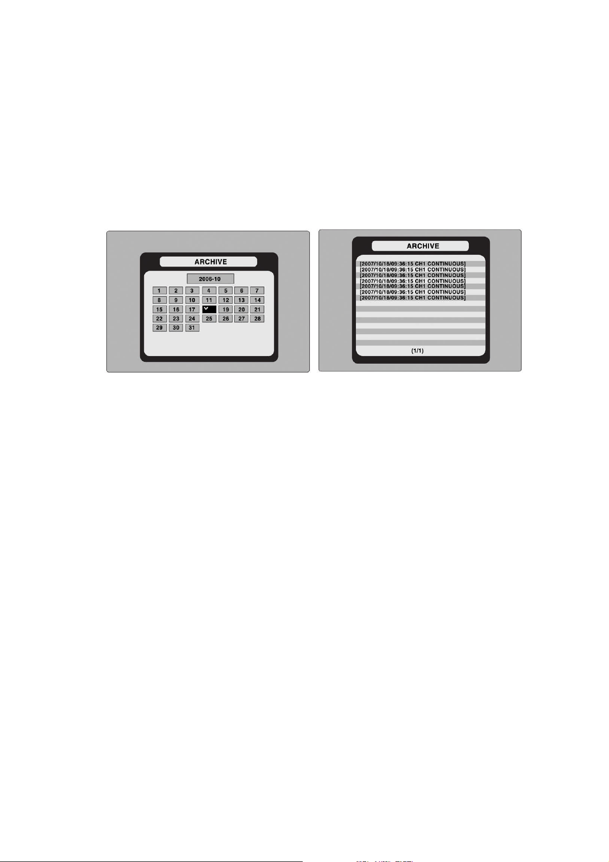
2. Once you have selected the date, press SEL to open the list of stored data.
3. Use the UP and DOWN buttons to scroll through the on-screen listings.
4. Use the LEFT and RIGHT buttons to display a list of stored events that happened
previous to or after the current selection.
5. Once the desired event has been selected, press SEL to view the still image or the first
frame of the selected video.
6. Press the BACKUP button to launch the archiving function in playback mode.
Figure 7.3.1. Archive Search Screen
7-4. Playback of Backup Video
7-4-1. Playback of backup video in AVI format
If the proper codec is not installed on your PC, the AVI file may not be played correctly. If this
happens, install the ‘FFDSHOW’codec that can download from open sites.
7-4-2. Playback of backup video in exclusive (NaFs) format
If the data is backed up in an exclusive file format, this video can be play backed only an
exclusive player in CD that is provided with DVR.
51
Page 52
8. Upgrading Firmware
In order to upgrade, the firmware upgrade file must first be downloaded and copied into the USB
memory stick. Create a new folder in the USB memory stick and name it “upgrade”. Copy the
firmware upgrade file “app16xxxxxx.bin” for 16CH DVR or “app9xxxxxx.bin” for 9CH DVR into
the “upgrade”folder.
NOTICE
The folder on the USB memory stick must be named “upgrade”.
After the firmware upgrade is copied into the USB memory stick, connect the USB memory stick
to the USB port on the front panel and do the following:
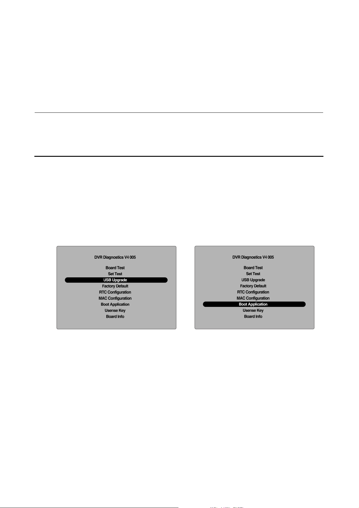
1. Press the SETUP button and enter the admin password.
2. Go to PASSWORD and select the ADMIN PASSWORD.
3. Enter the password as 12341234, and press the SEL button.
4. The engineering mode screen “DVR DIAGNOSTICS”will appear.
5. Select USB upgrade, and then the upgrading will start automatically.
6. After the upgrade is completed, select Boot Application to reboot DVR.
Figure 9.1.1. Engineering mode screen
52
Page 53
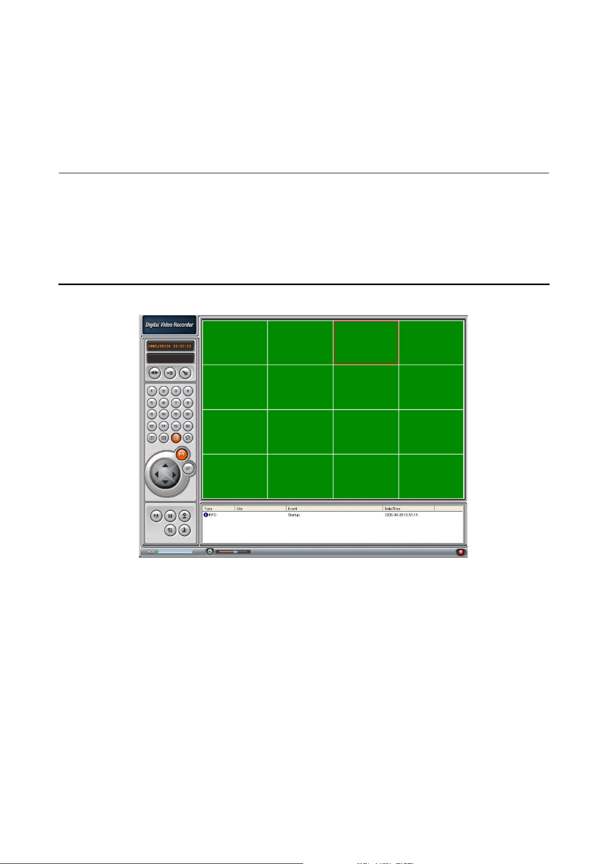
9. Network – By an exclusive viewer
The DVR provides a live remote monitoring feature. Remote monitoring requires installation of a
software client program on your PC.
NOTICE
In a high bandwidth network, a maximum of four users can access one DVR simultaneously. In
a low bandwidth network it is recommended that only one user access the DVR at a time.
For remote viewing, the frame rate is limited to 1 frame/sec when there is no recording
operation in the DVR. When the DVR is recording, the video frame rate for remote live
monitoring will follow the recording frame rate on the DVR.
Figure 9.1. Main user interface
9-1. Overview
The remote software supports remote live viewing, search, playback and system configurations.
By installing the Network Client Viewer on a Windows PC, you can monitor real-time and
recorded images via optional Ethernetnetwork.
53
Page 54
9-2. Minimum PC requirements
PC Specification Minimum Requirement Recommended
CPU Intel Pentium Ⅲ Intel Pentium Ⅳ
500Mhz 2Ghz
Memory 128MB 256MB
VGA 16MB 64MB
Resolution 1024x768 1024x768
Disk space 10MB 10MB
OS Windows 2000 Windows 2000, Professional, XP
Vista
Network 10/100Base T 10/100Base T
Others Direct X 8.1 Direct X 9.0 or Higher
Before installing the program, check the PC specifications. The Network Client Viewer may not
perform correctly if the PC does not meet the minimum requirements.
9-3. Installing the program
1. Insert the provided CD into the CD-ROM drive of your PC.
2. Run to start the installation process.
3. Follow the on-screen directions.
4. Double click the icon to start the program.
54
Page 55
9-4. Live viewer
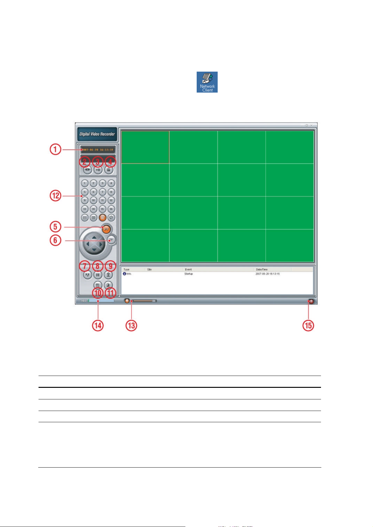
When installation is complete, double click the icon on your desktop to start the
program.
Figure 9.4.1. Main user interface
Table 9.4.1. Main controls in Live
NO Button Description
1
DATE & TIME
2
CONNECT
3
SEARCH
4
LOCK/ UNLOCK
Displays the current date and time.
Click this icon to connect to the DVR
Click this icon to search for recorded video.
Click this icon to lock/unlock all operations of the client software.
Once the lock or unlock icon is clicked, this pop up window
appears. Remember the password and enter it when you
operate the client software.
55
Page 56
5
PAN/TILT
Use these buttons to control the PAN/TILT features on the
remote camera.
6
ZOOM/ FOCUS
7
CAPTURE
8
PLAY/PAUSE
9
RECORD
10
SETUP
11
EXIT
12
DISPLAY MODE
13
AUDIO
Use these buttons to control the ZOOM/ FOCUS features on the
remote camera.
Click this icon to capture a still image.
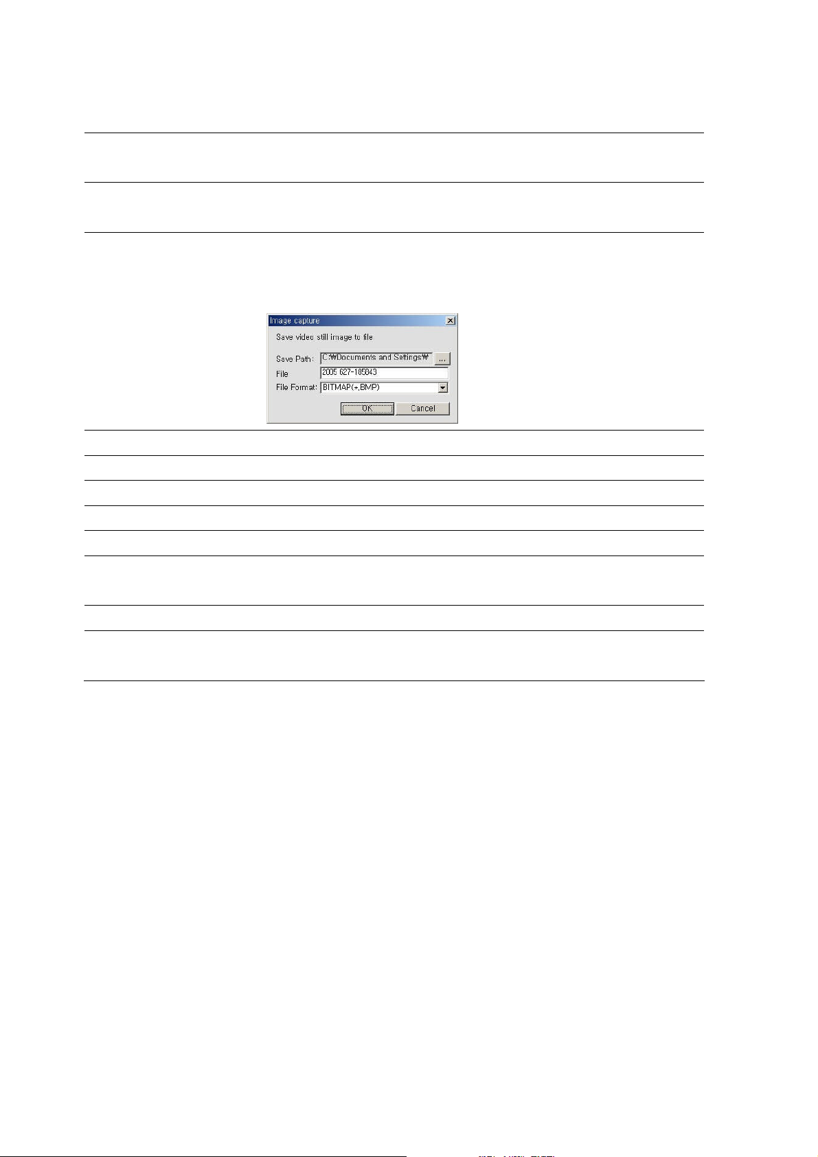
Once the capture icon is clicked, this pop-up window appears.
The still image is captured in either jpeg or bmp file format.
Click this icon to play/pause live video.
Enable or disable recording of live video to local disk.
Click this icon to setup configuration of client software.
Click this icon to exit the client software.
Click these icons to select display mode.
Use the volume control bar to set the audio level.
The audio can be turned on or off by clicking the audio icon.
14
HDD USAGE
15
ALARM
DVR HDD storage Indicator.
The alarm output indicator lights up for 5 seconds if alarm
output is activated on the DVR.
56
Page 57
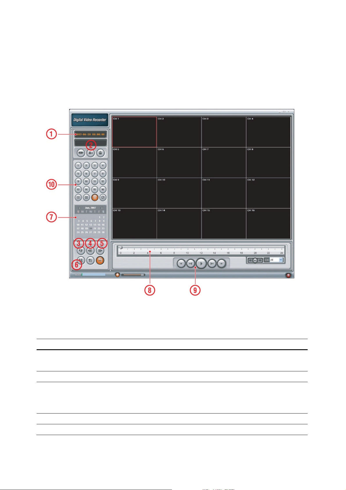
9-5. Search and Playback Viewer
The search window can be accessed by clicking the search icon on the upper right of the main
user interface.
Figure 9.5.1. Main user interface
Table 9.5.1. Main controls in Search
No Button Description
1 DATE & TIME
2 LIVE
3 CAPTURE
4 MARK IN
5 MARK OUT
Displays the recording time of the data selected on the time bar at
the bottom of the main user interface.
Click this icon to see live video.
Click this icon to capture a still image of recorded video.
Once the capture icon is clicked, this pop up window appears.
The still image is captured in either jpeg or bmp file format.
Click this icon to set the start time for video backup.
Click this icon to set the ending time for video backup.
57
Page 58
6 BACKUP
Click this icon to backup the selected recorded video in AVI
format.
7 SEARCH
CALENDAR
8 TIMELINE BAR
9 PLAY BUTTONS
10 DISPLAY MODE
The calendar shows dates with recorded video in a light blue and
the selected date in dark blue.
The timeline shows recorded data in dark blue on the bar. You can
adjust the time-line scale and move it to the time you wish to play
back. Click the play icon to display the recorded video.
Click these icons to select display mode.
9-5-1. Backup
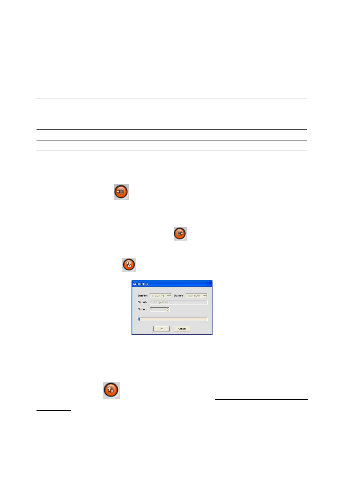
You can back up recorded video in AVI format from the search viewer.
1. Click the MARK IN icon when the scale on the blue timeline is on the time you wish to
the backup file to begin.
2. Set the ending time on the blue timeline by dragging the scale to the ending time for the
backup file and clicking the MARK OUT icon . The color of the timeline between the
beginning time and ending time will change to dark green.
3. Next, click the backup icon and the pop up window appears as below.
The beginning and ending time can also be set on this window.
After selecting a channel for backup, click the OK button. The backup will begin.
9-6. PC System configuration
Click the setup icon to setup the configuration of PC that the network client S/W
is installed.
9-6-1. General
Once you click the setup icon, this pop up window appears. Select security options and set a
password. When you access any of the selected functions, you will need to enter the password.
58
Page 59
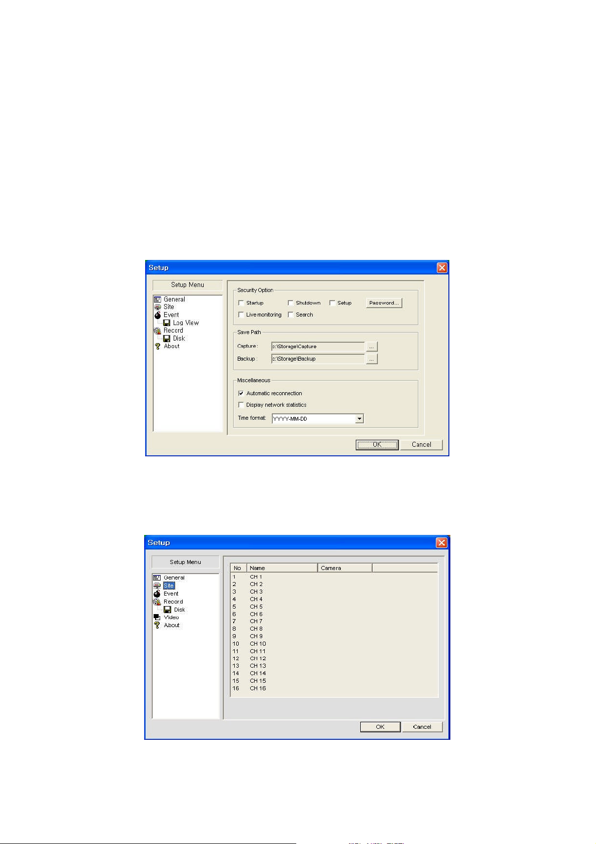
You can also set the save path for capturing and backup.
Security Option: Set a password for security options.
Save Path: Specify the location to record the receiving video for Backup and still image for
Capture.
Automatic reconnection: If a user selects this function, the client S/W will automatically try to
connect to the previously connected IP address if the network connection is lost.
Display network statistics: If a user selects this function, the client S/W will display network
status, Bit rate and Frame rate.
Time Format: Change the way the Client software displays the time.
9-6-2. Site
This option shows the channel information of the DVR and allows you to change the channel
title.
59
Page 60
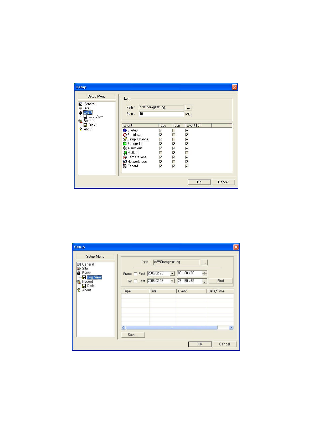
9-6-3. Event
You can set event items, the amount of local disk space you want to allow and the save path for
the log file.
LOG – Select to save event log into ‘log file’.
ICON – Select to display the event on live video.
EVENT LIST – Select to show the event in the ‘Event List”window of live mode.
You can search and check the recorded log data.
9-6-4. Record
You can set the recording conditions for Always, Event, or Auto recording. You can also select
individual channels or all channels to record.
60
Page 61
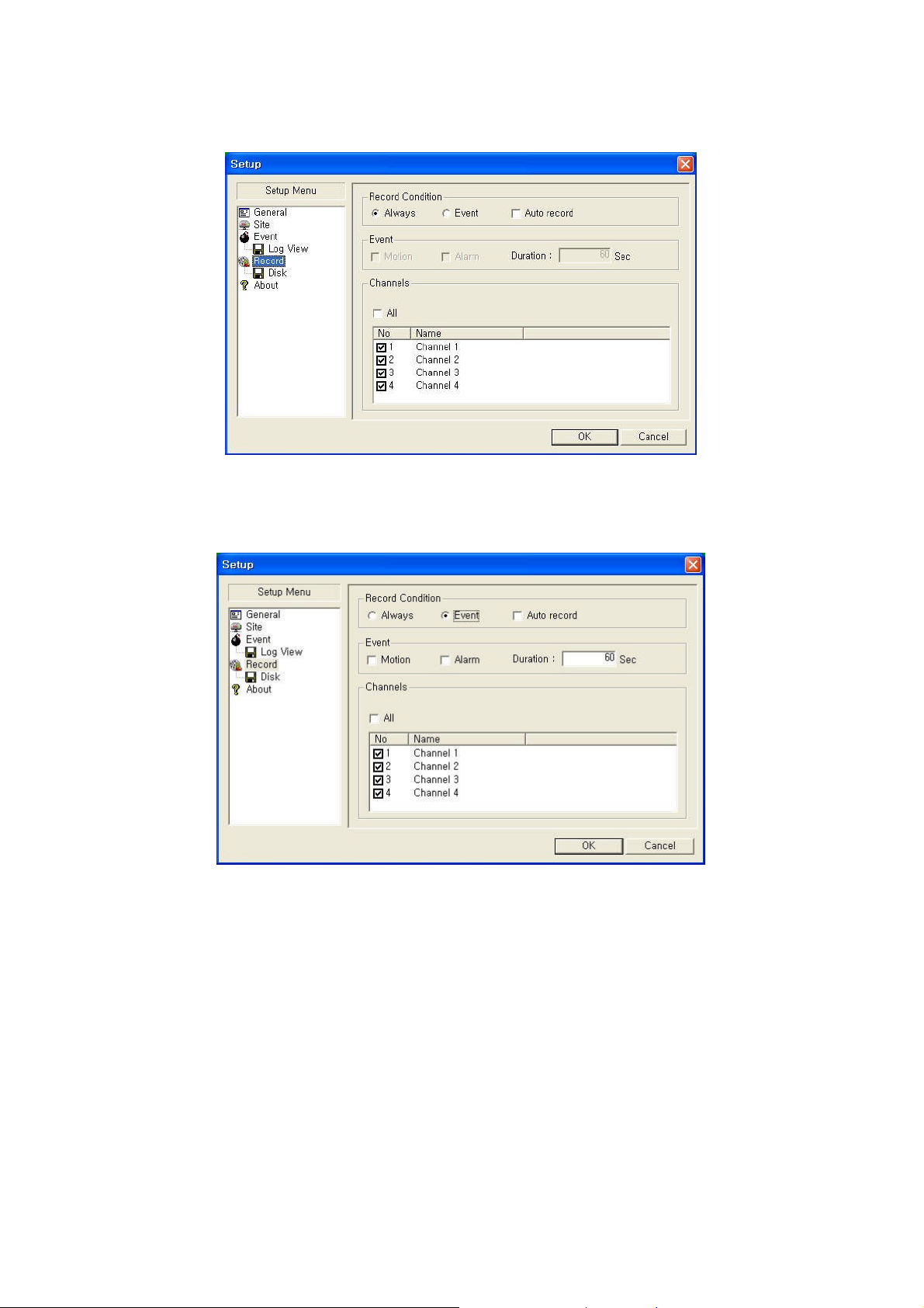
When you set the recording condition to Event, you can set event for motion or alarm with
duration. You can also set each or all channels to record.
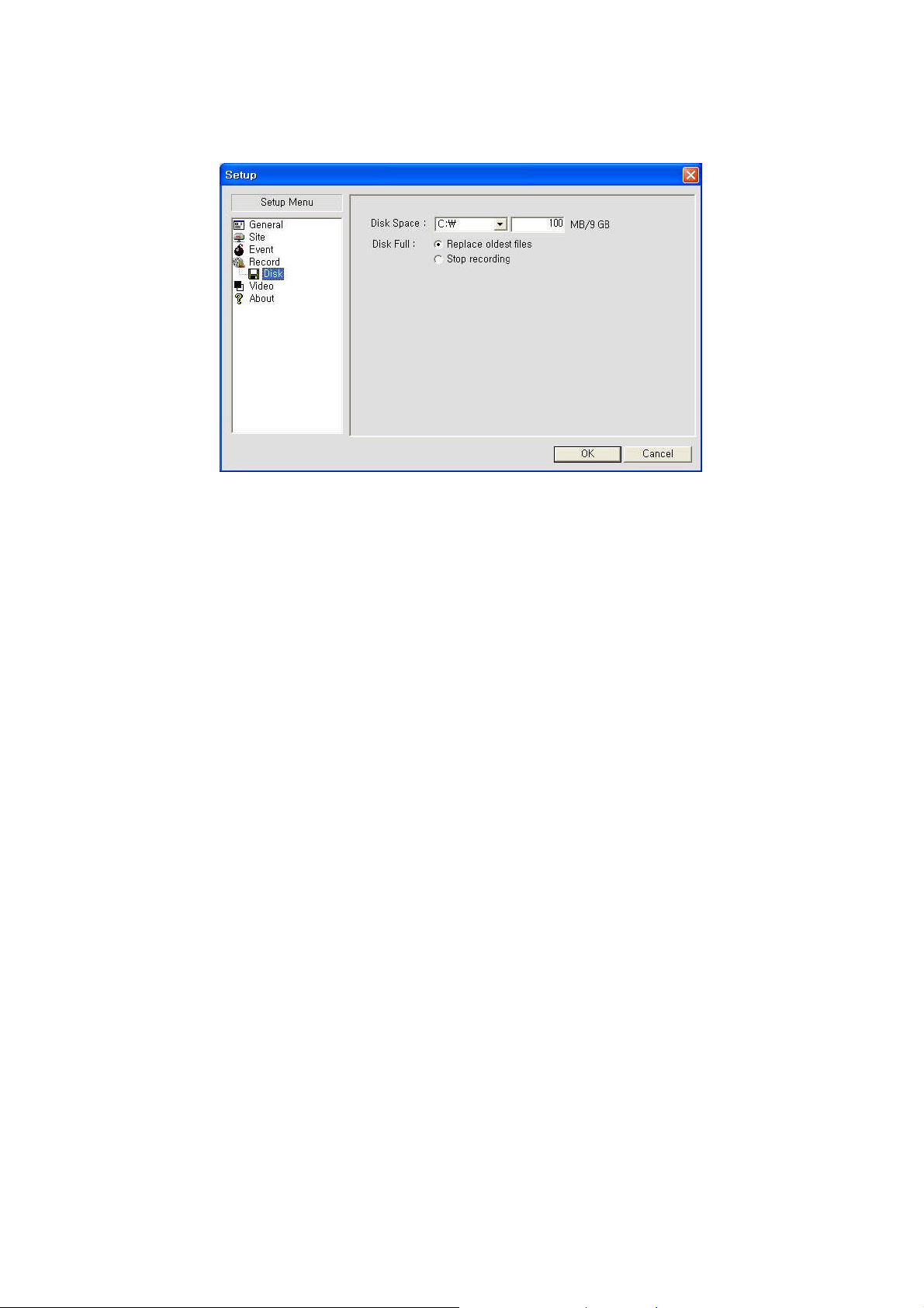
9-6-5. Disk
You can select which local disk to use and the amount of disk space you want to allow the
program to use for recording. You can also choose to overwrite data or stop recording when the
maximum amount of disk space is full.
61
Page 62
62
Page 63
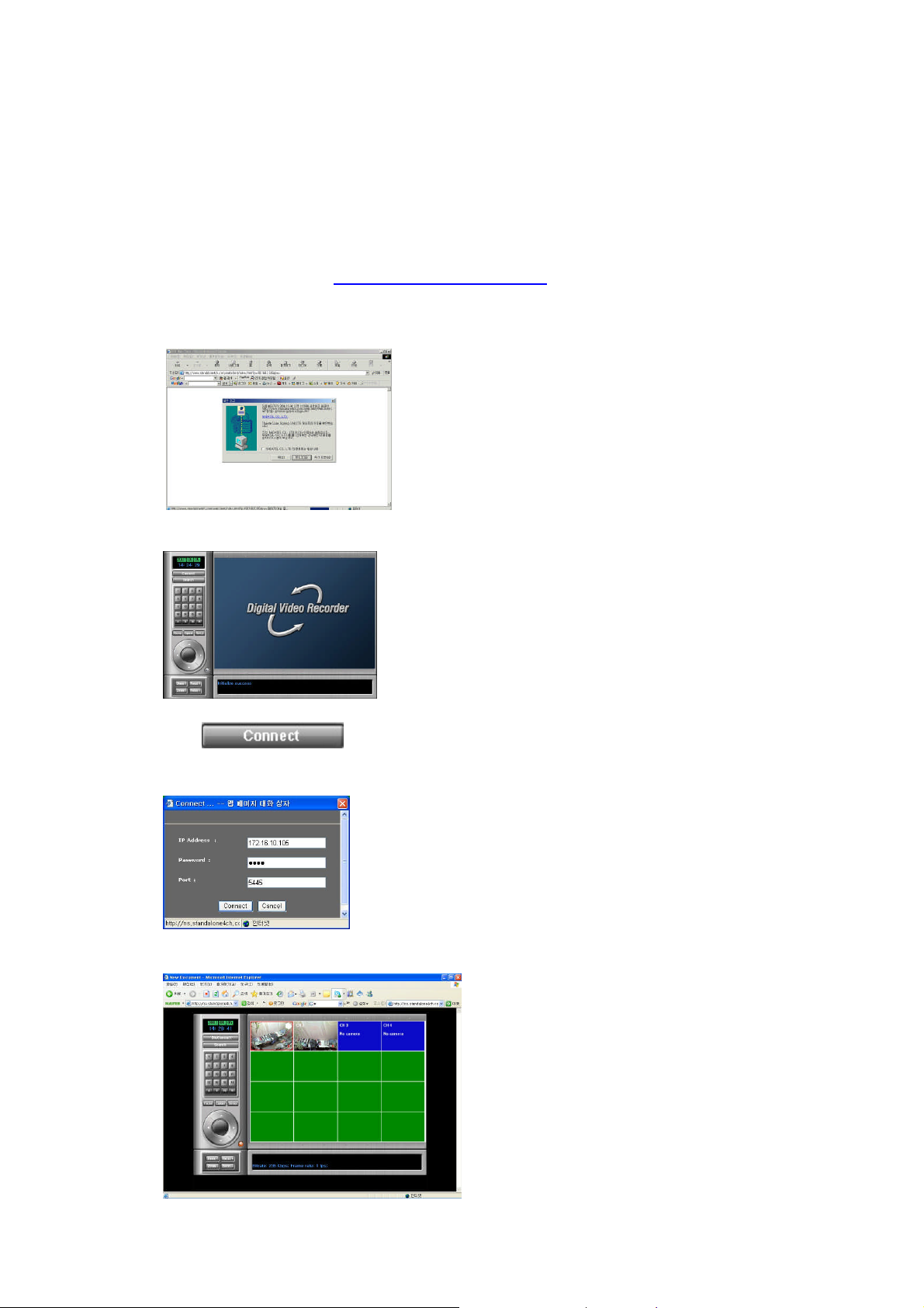
10. Network – By an web-browser viewer
The DVR provides a live remote monitoring feature by web-browser viewer.
10-1. Download Web Brower Viewer and Connection
1. User needs to access http://www.anytimeview.com to get a web browser viewer. Then
the window will appear as bellow. Click “YES” to download Web Browser Viewer from
the server run by the manufacturer.
2. Web Browser Viewer will be downloaded and installed.
3. Click button and enter IP address (or Domain name using DDNS),
the password, and Port number.
4. Then user can access DVR.
63
Page 64
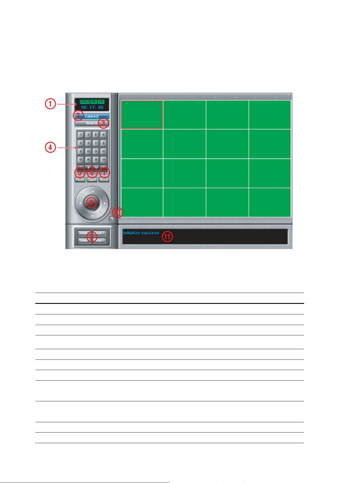
10-2. Main Features
10-2-1. Live
Figure 10.2.1. Main user interface - Live
Table 10.2.1. Main controls in Live
No Name Description
1
DATE & TIME
2
CONNECT
3
SEARCH
4
LIVE DISPLAY MODE
5
PAUSE
6
CAPTURE
7
SETUP
8
PAN/TILT
9
ZOOM/FOCUS
10
AUDIO
Displays the current date and time.
Click this icon to connect to the DVR
Click this icon to search for recorded video.
Click these icons to select display mode.
Click this icon to pause the display screen.
Click this icon to capture the image from live display.
Click this icon to control remotely the setting of DVR.
Use these buttons to control the PAN/TILT features on the
remote camera.
Use these buttons to control the ZOOM/ FOCUS features on
the remote camera.
The audio can be turned on or off by clicking the audio icon.
11
CONNECTION STATUS
Shows the client connection information.
64
Page 65
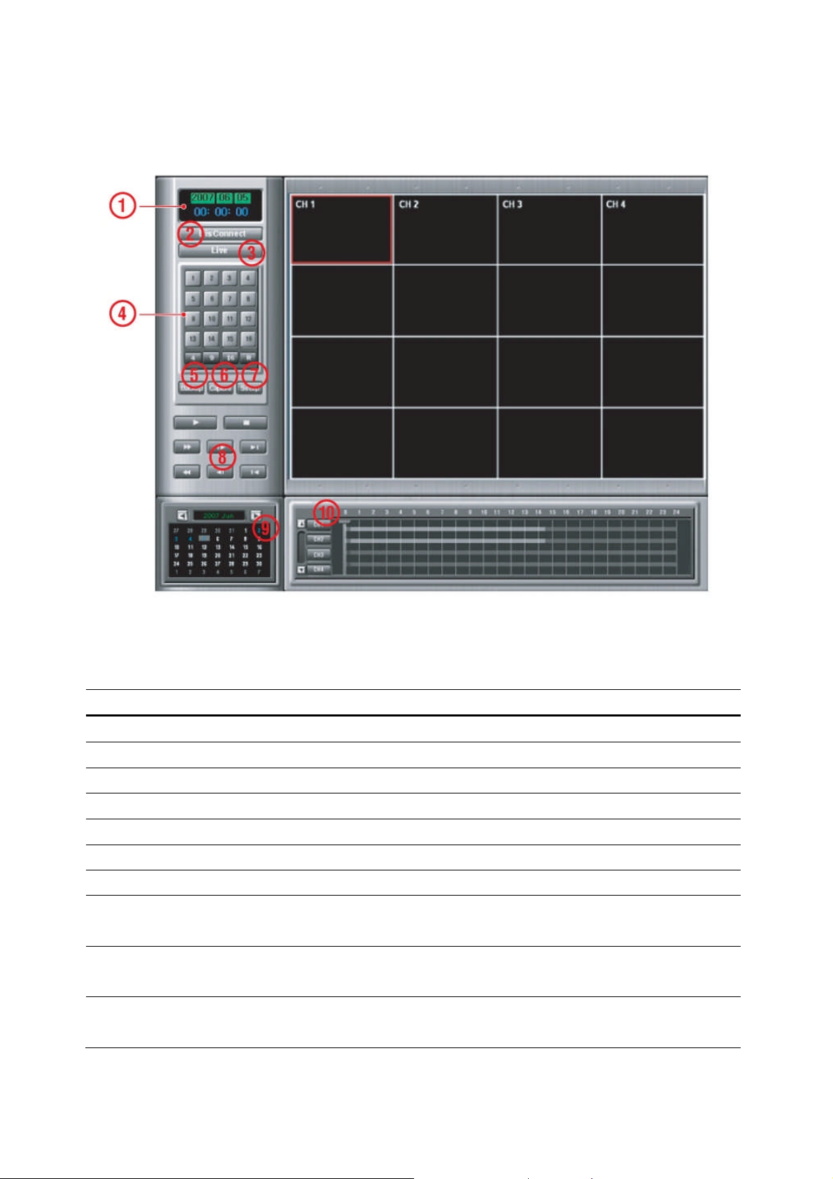
10-2-2. Search and Playback
Figure 10.2.2. Main user interface – Search & Playback
Table 10.2.2. Main controls – Search & Playback
No Name Description
1
DATE & TIME
2
Connect/Disconnect
3
LIVE
4
DISPLAY MODE
5
BACKUP
6
CAPTURE
7
SETUP
8
PLAYBACK BUTTONS
9
SEARCH CALENDAR
10
Timeline Search
Displays the current date and time.
Click this icon to connect to the DVR
Click this icon to search for recorded video.
Click these icons to select display mode.
Click this icon to pause the display screen.
Click this icon to capture the image from playback.
Click this icon to control remotely the setting of DVR.
Use these buttons to control the PAN/TILT features on the
remote camera.
Use these buttons to control the ZOOM/ FOCUS features on
the remote camera.
The audio can be turned on or off by clicking the audio icon.
Window
65
Page 66
APPENDIX
A. How to open TCP port on Router?
1. Connect network cable between DVR and Switch / Hub or Router.
2. Network setting on DVR are Port: 5445, IP ADDRESS: 172.16.1.52, Subnet: 255.255.0.0, Gateway: 0.0.0.0
as default.
3. From PC connected in the same Router, find IP address, Gateway, and Subnet by IPCONFIG command in
command prompt.
4. But if IP is something else like 192.168.1.xxx., you should change IP address, Subnet, Gateway on DVR.
Go to SETUP>NETWORK of DVR and change the IP settings to be like IP: 192.168.000.XXX and
Gateway: 192.168.1.1. (Refer to the user’s manual of Router.)
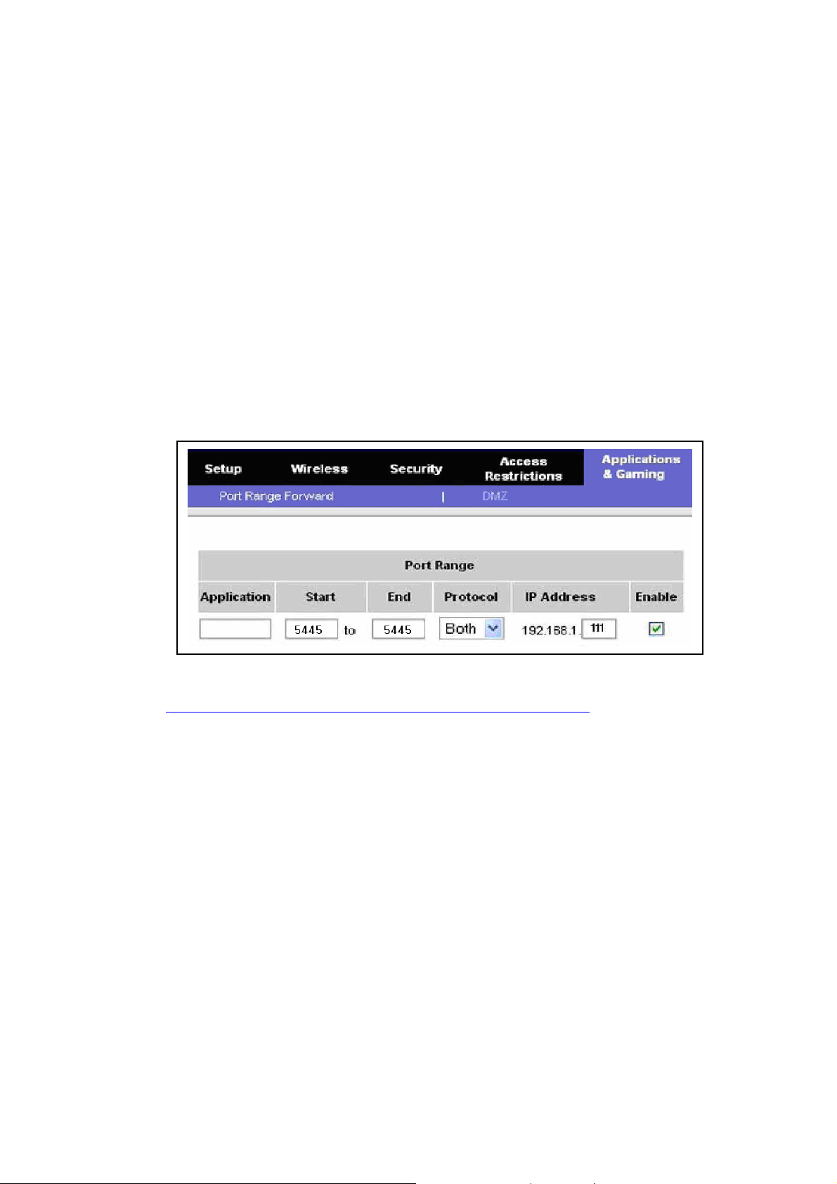
5. Then, go to Router Setup and you should open TCP port 5445 using Port Forwarding.
You can learn how to port forward many kinds of Routers from the bellow site.
http://www.portforward.com/english/routers/port_forwarding/routerindex.htm
B. How to access DVR from Remote PC?
If DVR and Remote PC are in the same local network (LAN), then go to B-1.
If DVR is in other Wide Area Network (WAN) and you will access with IP address, then go to B-2.
If DVR is in other Wide Area Network (WAN) and you will access with DDNS service and Domain
Name, then go to B-3.
B-1. How to access DVR from Remote PC in the same local network?
1. Install network client software on CD.
2. Check the IP address from SETUP>SYSTEM>DESCRIPTION of DVR.
3. Run network client software.
66
Page 67
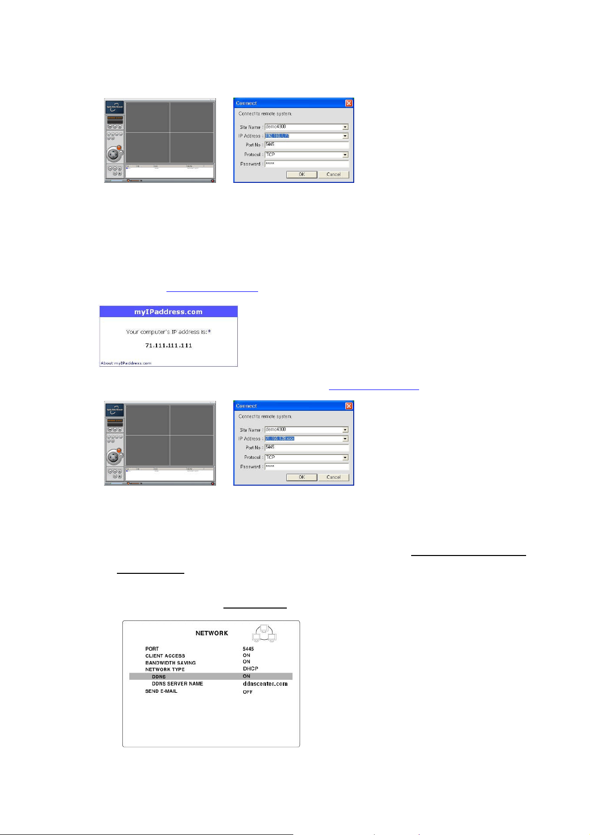
4. Click CONNECT button.
5. Input IP address, Port No., and Password. And click OK
B-2. How to access DVR from Remote PC with IP address?
1. User can find this external IP address of Router from the PC connected to the same Router where the DVR
is installed from www.myipaddress.com
2. Install network client software on CD and run it or access www.anytimeview.com
3. Click CONNECT button.
4. Input the external IP address of Router, Port No. (This port must be opened.), and Password. And click OK.
B-3. How to access DVR from Remote PC with DDNS service when DVR is linked on
Dynamic IP?
1. Go to SETUP>NETWORK. Set NETWORK TYPE as DHCP and DDNS SERVER as ON. And make sure
that DDNS SERVER NAME is ddnscenter.com
2. Go to Setup menu of Router and open TCP port 5445 using Port Forwarding.
67
Page 68
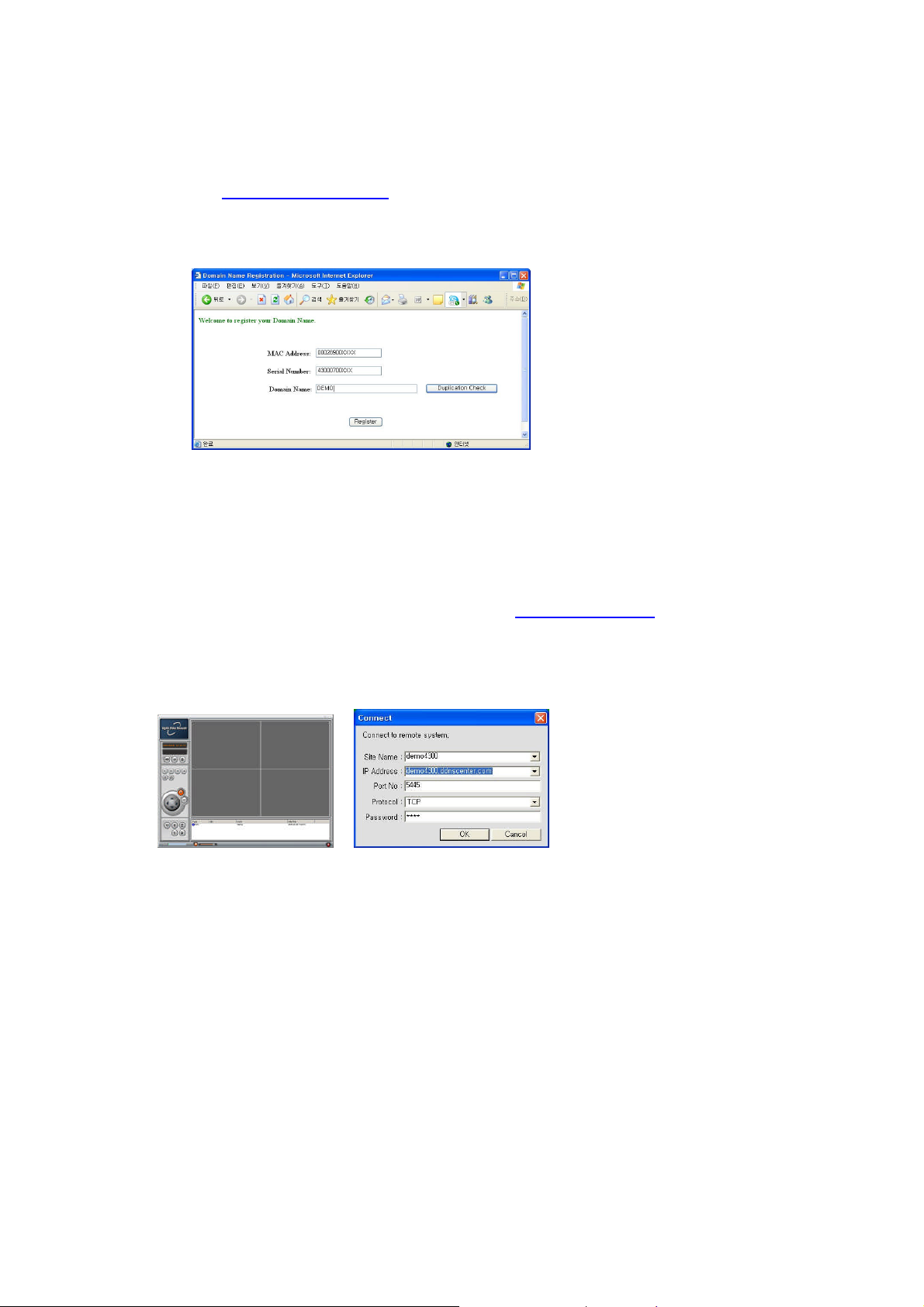
3. Write down the Mac address and Serial No. from the label of the rear panel of DVR.
4. Log on to http://www.ddnscenter.com
5. Input the Mac address (EX. 0002690XXXXX) and Serial No. (EX. 43000700XXX.) in each field. (Note. Input
Serial No. and Mac address without a space.)
6. Create a Domain Name for your DVR system and input it in the field provided. (Note. Input only Domain
Name and never input “ddnscenter.com”.)
7. Click the DUPLICATION CHECK button to see if the domain name is available.
8. If you see the screen “You can use the Domain name you entered”then click RETURN and click
REGISTER button to complete the registration.
9. Install network client software on CD and run it or access www.anytimeview.com.
10. Click CONNECT button.
11. Input the Domain Name that you registered, Port No. (This port must be opened), and Password. And click
OK.
68
 Loading...