

Pelican Z8 Installation Manual

Z8 Wireless Zone Controller
Pelican
Wireless Systems
Pelican
Wireless Systems
Pelican Wireless Systems, 2655 Collier Canyon Rd. Livermore, CA 94551
Phone: 888.512.0490
Email: support@pelicanwireless.com Website: www.pelicanwireless.com
Installation Guide

Table of Contents
2
PRE-INSTALLATION CONSIDERATIONS
Before installing any zoning system forethought and planning should take place to identify which type of HVAC
equipment the Z8 will be controlling, how many stages the equipment has, how many zones are going to be
conditioned, and what the square footage of each zone is for the size of the HVAC equipment. Because the Z8
uses wireless communication, plan installation locations appropriately for each Pelican device. Contact Pelican
Support at 888.512.0490 for further assistance.
GENERAL
The Pelican zone control solution uses strategic logic and built-in learning algorithms to properly condition
spaces or areas of diverse load. The zone controller uses sensors and software to monitor temperatures and duct
pressure to intelligently navigate complex building environments. The zone controller is a pressure dependent
device that maintains space temperature by modulating the amount of supply airflow brought into different spaces.
To aid in decision making, space or zone temperatures and total building load is continuously monitored and
wirelessly communicated to the zone controller from Pelican thermostats installed through-out the building. During
times when zones are being conditioned, rate of temperature change relative to set point is monitored and logic is
dynamically adjusted. This data allows the zone controller to satisfy the temperature and ventilation requirements
for each zone in a timely and energy efficient manner.
Specifications
Provided Equipment
Terminal Designations
Installation
Installation Process
Mounting
Wireless Module
Conventional Wiring Diagrams
Conventional System
Conventional System with Bypass
Conventional System with Bypass and Economizer
Conventional System with Variable Speed Fan (VFD)
Conventional System with Variable Speed Fan (VFD) and Economizer
Conventional System with Economizer
Heat Pump Wiring Diagrams
Heat Pump
Heat Pump with Bypass
Heat Pump with Bypass and Economizer
Heat Pump with Variable Speed Fan (VFD)
Heat Pump with Variable Speed Fan (VFD) and Economizer
Heat Pump with Economizer
Boiler Wiring Diagram
Setup and Configuration
Troubleshooting
3
3
4
6
10
12
13
15
16
17
18
19
20
21
22
23
24
25
26
27
28
31

(2) 0.25” diameter
10K Type II Duct Probes
(1) 10K Type II Outdoor
Temp. Probe
(1) Static Pressure Sensor
SPECIFICATIONS
PROVIDED EQUIPMENT
Electrical
Power
Relay Current
Variable Output
Thermistor Input
Pressure Range
24 VAC
1 AMP @ 24V
0-10 VDC
10K Type II
0 – 9" WC
Wireless Module
Z8 Controller
(1) Electrical Box Gasket
3
(2) 3/16” Sheet Metal Screws
(Z8 Mounting)
(4 ) 3/16” Machine Screws
(Wireless Module Mounting)
20 Feet 1/8” Plastic Tubing
4
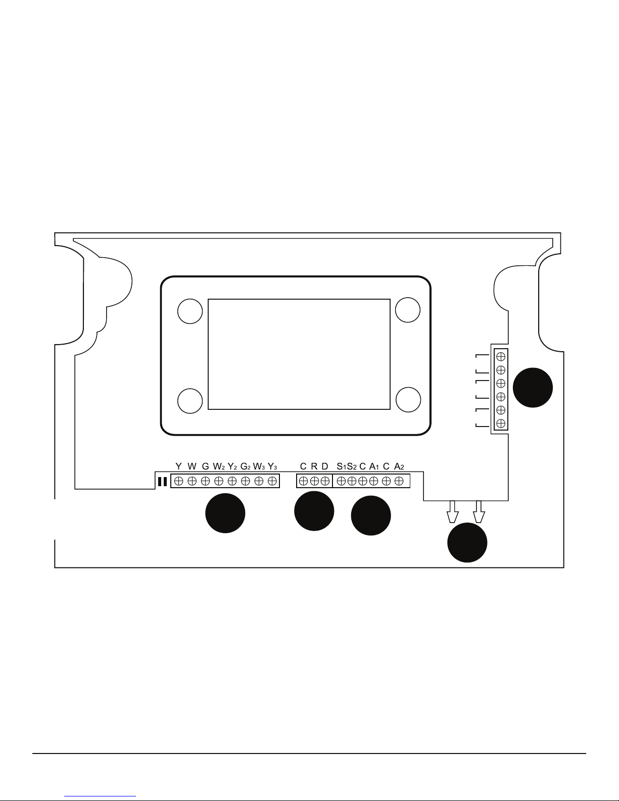
TERMINAL DESIGNATIONS
A
B
C
D
E
Pressure
High Low
T
1
T2
T3
Fig. 1
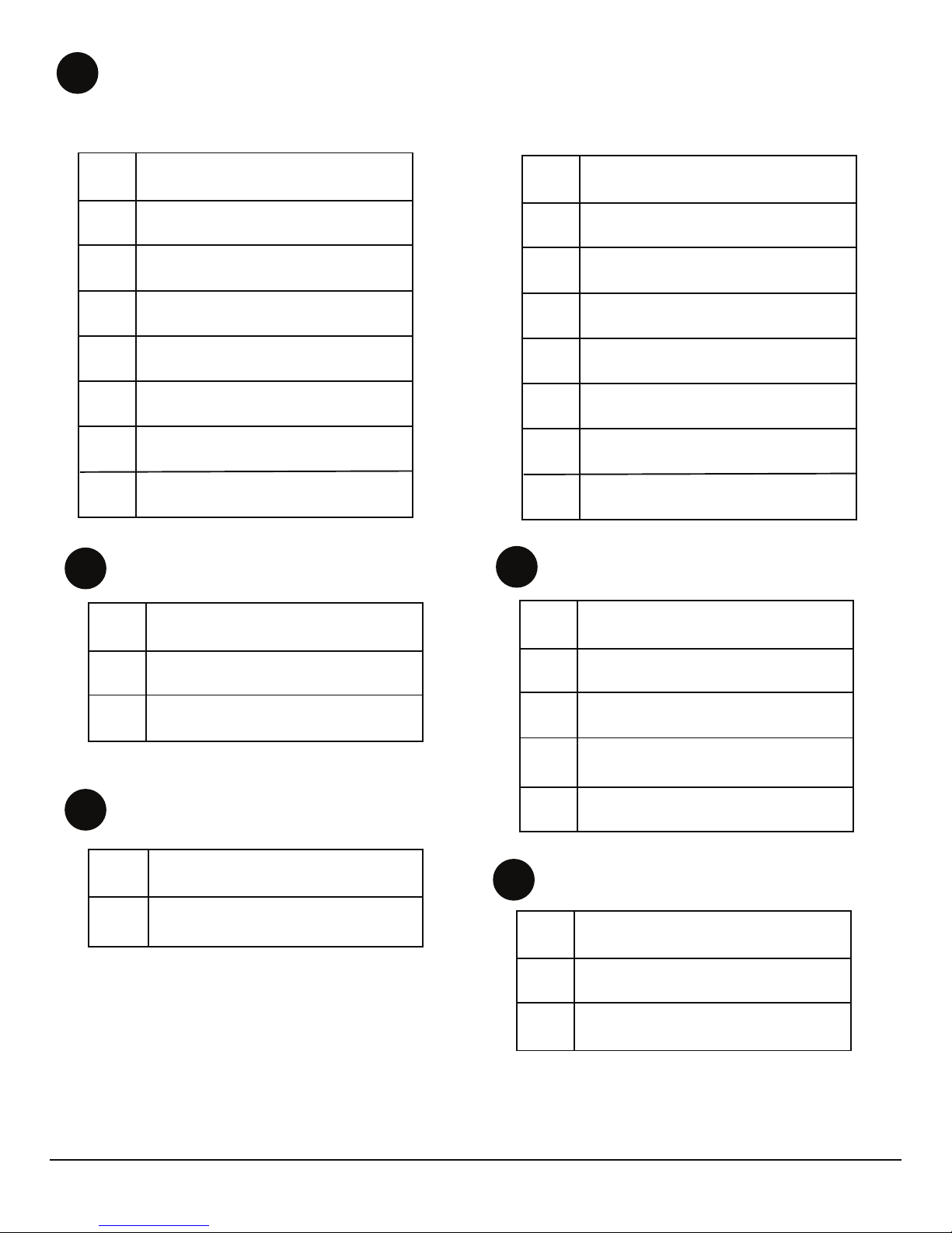
Note:
“T” Terminals can accept either Type 2 10K
temperature probe or a Dry Contact Sensor input
to send an alarm notification through your
Pelican Site Manager.
Heat Pump
Conventional
Y
W
G
W2
Y2
G2
W3
Y3
W
G
W2
Y2
G2
W3
Y3
HVAC UNIT CONTROL (24VAC Digital Outputs)
Compressor Stage 1
Compressor Stage 2
Compressor Stage 3
Heat Stage 1
Heat Stage 2
Heat Stage 3
Fan Energize
Exhaust Fan Energize
Compressor Stage 1
Compressor Stage 2
Compressor Stage 3
(O/B) Reversing Valve
(AUX) Electric Heat
(Not Used)
Fan Energize
Exhaust Fan Energize
A
Y
C
R
D
Common 24 VAC
24 VAC Power
Data
ELECTRICAL CONNECTIONS
B
0-10VDC INPUTS/OUTPUTS
S1
S2
C
0-10 VDC input
Common
0-10 VDC input
A1
A2
0-10 VDC output
0-10 VDC output
T1
T3
Input Terminal
Input Terminal
Input Terminal
High
Low
Duct Pressure
Outside/Ambient Pressure
C
STATIC PRESSURE SENSOR
D
10K ANALOG INPUTS
E
T
2
5

Installation
LOCATION AND MOUNTING
Location
Choose a location for the Z8 that is not exposed to weather, and where controls and connections
are accessible. The Wireless Module can be removed from the Z8 and is waterproof if installed
onto a plastic electrical box with the provided gasket placed in-between (Reference Page 13).
Gasket is required to create a water tight seal between Wireless Module and plastic electrical
box (Reference Page 14).
CAUTION
1. Disconnect power supply before connecting any wiring to device to prevent
electrical shock or damage to equipment.
2. This guide is designed for certified, trained, and experienced service technicians.
Failure to follow installation instructions does not alleviate installer responsibility to
protect the equipment and property device is being connected too. If at anytime there
becomes concern or confusion about how to install or use this device, immediately
stop what you are doing and either contact Pelican Wireless Systems or a Pelican
Wireless System’s distributor.
WARNING
1. This equipment is designed to communicate over radio frequency to other Pelican
equipment only. If this equipment is not installed and used in accordance with the
instruction manual, you may experience wireless interference. This device has been
tested and complies with FCC rules and regulations.
CAUTION
Always remove the Wireless Module if the Z8 is installed enclosed in metal (e.g.
inside the HVAC unit). The Wireless Module will not be able to communicate if metal
is blocking its signal.
WHEN INSTALLING THIS PRODUCT...
1. Read these instructions carefully and thoroughly. Failure to follow these instructions or
improper installation, service, adjustments, maintenance, and/or use can result in personal
injury, damage to personal property, and/or cause a hazardous and dangerous situation.
2. Check the ratings and description given in this specification to make sure the product is
suitable for your application.
3. Installer must be a trained and experienced technician. Follow all safety codes and
regulations and all local and state building codes. Read instructions thoroughly and follow
all warnings or notes.
4. After installation is complete, check product operation as provided in these instructions.
6
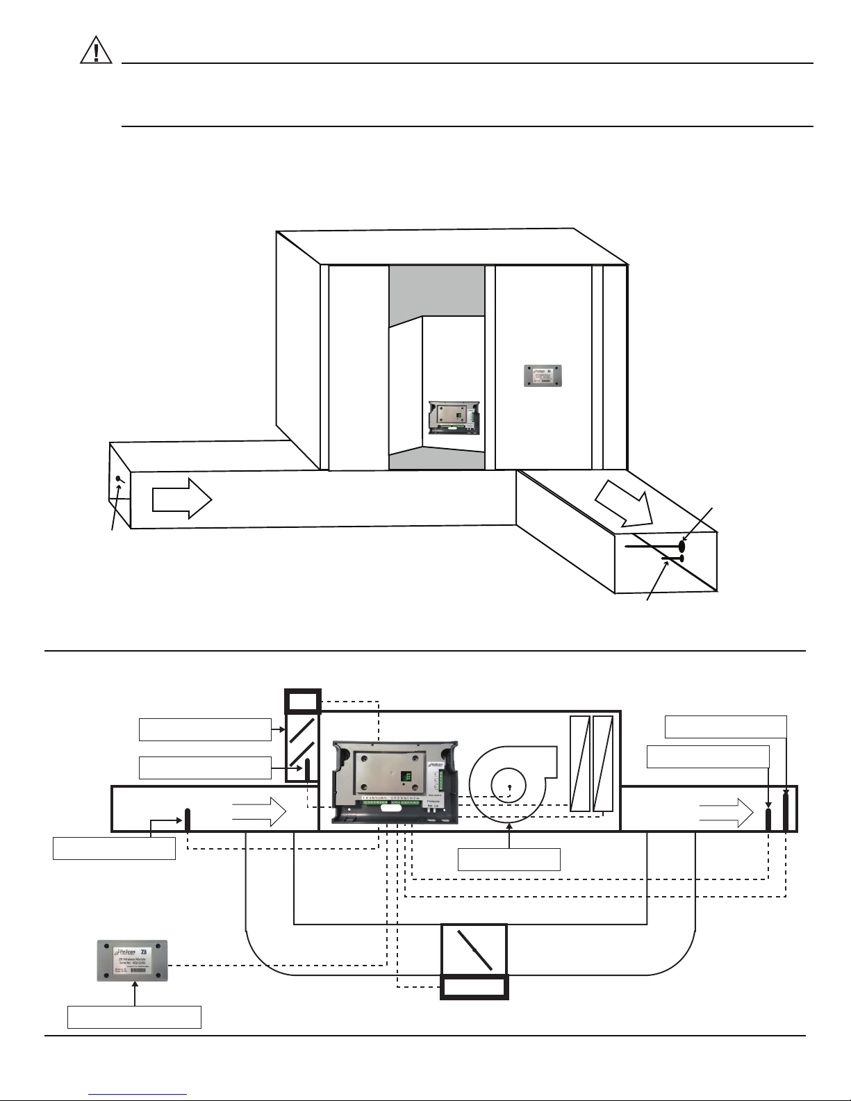
Mounting examples are shown below are for reference. Additional examples can be found at
www.pelicanwireless.com.
Wireless Module
Inside HVAC
unit
Supply Air
Temperature
Probe
Return Air
Temperature
Probe
Outside HVAC
unit
Z8
Static Pressure
Sensor
Fig. 2 – Typical mounting at HVAC unit.
Fig. 3 – Typical single duct system with bypass and economizer.
WARNING
If installing the Wireless Module outside, make sure it is installed onto a PLASTIC
electrical box. Make sure a proper seal is created between the Wireless Module, the
provided gasket, and the contact edge of the plastic electrical box.
BLOWER MOTOR
BYPASS DAMPER
RETURN DUCT
OUTSIDE AIR DAMPER
AIRFLOW
SUPPLY DUCT
WIRELESS ANTENNA
OUTSIDE AIR PROBE
RETURN AIR PROBE
SUPPLY AIR PROBE
DUCT STATIC PROBE
AIRFLOW
Economizer
Damper Motor
INSIDE AIR HANDLER
AC COIL
AC COIL
HEAT
HEAT
OUTSIDE AIR HANDLER
7

8
HOT DECK SUPPLY
SUPPLY AIR PROBE
DUCT STATIC PROBE
AIRFLOW
COLD DECK SUPPLY
SUPPLY AIR PROBE
DUCT STATIC PROBE
AIRFLOW
AC
AC
RETURN AIR
AIRFLOW
RETURN AIR PROBE
RETURN AIR PROBE
HEAT
HEAT
VARIABLE SPEED
BLOWER
OUTSIDE AIR PROBE
Z8 (COLD DECK)
VARIABLE SPEED BLOWER
RETURN DUCT
OUTSIDE AIR DAMPER
AIRFLOW
SUPPLY DUCT
OUTSIDE AIR HANDLER
WIRELESS ANTENNA
OUTSIDE AIR PROBE
RETURN AIR PROBE
SUPPLY AIR PROBE
DUCT STATIC PROBE
AIRFLOW
Economizer
AC COIL
AC COIL
HEAT
HEAT
Fig. 5 – Typical mounting dual duct system with VFD and economizer.
Fig. 4 – Typical mounting single duct system with VFD and economizer.
Z8 (HOT DECK)
INSIDE AIR HANDLER
Economizer
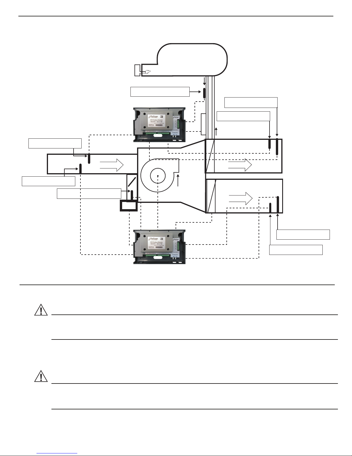
WARNING
If installing the Wireless Module outside, make sure it is installed onto a PLASTIC
electrical box. Make sure a proper seal is created between the Wireless Module, the
provided gasket, and the contact edge of the plastic electrical box.
Z8 (HOT DECK)
HOT DECK SUPPLY
SUPPLY AIR PROBE
DUCT STATIC PROBE
AIRFLOW
COLD DECK SUPPLY
SUPPLY AIR PROBE
DUCT STATIC PROBE
AIRFLOW
AC
AC
RETURN AIR
AIRFLOW
BOILER
RETURN AIR PROBE
RETURN AIR PROBE
BOILER TEMP. PROBE
HEAT
FLOW
FLOW
PUMP/VALVE
HEAT
VARIABLE SPEED
BLOWER
OUTSIDE AIR PROBE
Fig. 6 – Typical mounting dual duct system with VFD, economizer, and
boiler for hot deck.
CAUTION
Always remove the Wireless Module if the Z8 is installed enclosed in metal (i.e.:
inside the HVAC unit). The Wireless Module will not be able to communicate if metal
is blocking its signal.
Z8 (COLD DECK)
9
Economizer

INSTALLATION PROCESS
1. Remove the Z8 front cover by placing two fingers into indents along both sides of the controller.
Front cover should pull away from back panel with a small amount of upward force. This will expose
the terminal blocks, mounting holes, and wireless module.
2. Place the Z8 back plate on a flat surface for mounting. Mark mounting holes and drill 3/16” holes into
mounting surface (Refernce Page 12 Figure 7). Note the provided wiring channels. There is also a
channel for the static pressure tubing.
3. If the Z8 is installed inside the HVAC unit or is enclosed in metal. The wireless module will need to be
removed from the Z8 and installed either below the roof-line or outside the HVAC unit on a plastic
weatherproof electrical box (Reference Pages 13 and 14 Figures 8 and 9). The Z8 Wiring Guides are layed
out as follows:
a. Fig. 8 shows wiring the Wireless Module to the Z8. (Page 13)
b. Fig. 9 shows installing the Wireless Module on a plastic weatherproof electrical box. (Page 14)
c. Fig. 10 shows the Z8 wired to a Conventional HVAC unit. (Page 15)
d. Fig. 11 shows the Z8 wired to a Conventional HVAC unit with a Bypass. (Page 16)
e. Fig. 12 shows the Z8 wired to a Conventional HVAC unit with a Bypass and Economizer. (Page 17)
f. Fig. 13 shows the Z8 wired to a Conventional HVAC unit with a VFD. (Page 18)
g. Fig. 14 shows the Z8 wired to a Conventional HVAC unit with a VFD and Economizer. (Page 19)
h. Fig. 15 shows the Z8 wired to a Conventional HVAC unit with an Economizer. (Page 20)
Wire Channels
Static Pressure Tube Channel
Mounting Hole
Mounting Hole
Pressure
High Low
T
1
T2
T3
10
 Loading...