

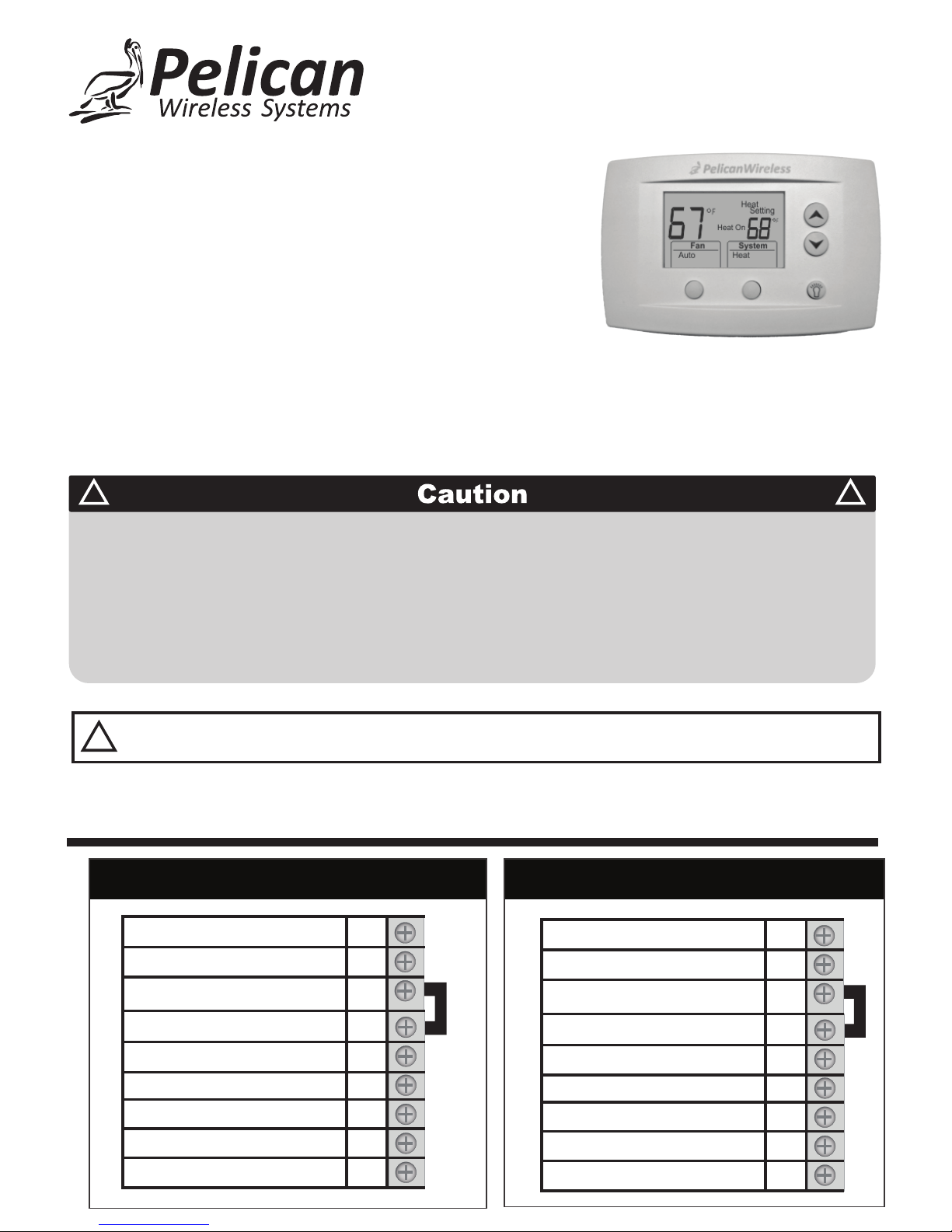
Pelican TS200, TS200H, TS250, TS250H Installation Manual
!
!
Failure to follow these instructions can damage the product or cause a hazardous
condition. Disconnect power during the installation of this product. All wiring must conform
to local codes and ordinances. We strongly recommend that any installation or servicing
be performed by a qualified technician. This thermostat is designed for use with 24VAC
systems only. For additional support contact Pelican Technical Support at 888-512-0490
or email support@pelicanwireless.com
WARNING
!
NEVER INSTALL THE PELICAN THERMOSTAT ENCLOSED IN METAL.
WIRELESS CANNOT COMMUNICATE THROUGH METAL.
Installation Guide
Internet
Programmable Thermostat
TS200
Thermostat Terminal Designations
D
C
R
DATA
COMMON
24VAC (COOL)
24VAC (HEAT)
Rc
Y
W
G
COOL STAGE 1
HEAT STAGE 1
FAN
W2
Y2
HEAT STAGE 2
COOL STAGE 2
D
C
R
DATA
COMMON
24VAC
24VAC
Rc
Y
W
G
COMPRESSOR STAGE 1
REVERSING VALVE (O/B)
FAN
W2
Y2
AUXILIARY HEAT
COMPRESSOR STAGE 2
Conventional Control Heat Pump Control
Before Removing the Old Thermostat!
Note the wire colors and letter designations of the existing thermostat to
assist in identifying the correct wiring connections to the TS200.
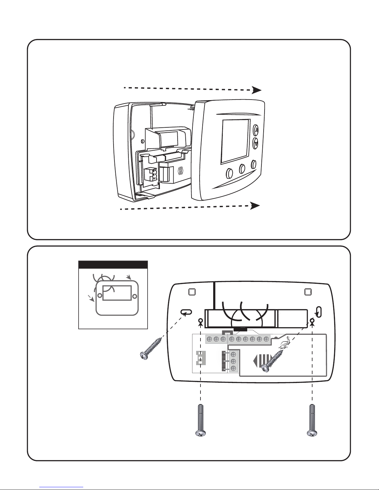
TS200 Mounting and Assembly
1
Mount thermostat rear cover to the wall.
2
2
Old thermostat
Remove old thermostat
Option One:
Mark mounting holes
drill two 3/16” holes in
wall. Insert drywall anchors
and use provided sheet metal
screws to attach rear
cover to wall.
Rc
CD R
R
C
D
Y W G W Y2 2
Pelican
Wireless Systems
Wiring Module
Model: WM500
Power: 24-30 VAC
PelicanWireless.com
Grasp front and back of thermostat and firmly pull apart.
Option Two:
Mount rear cover on
horizontal two gang
electrical box. Use
included machine
screws.
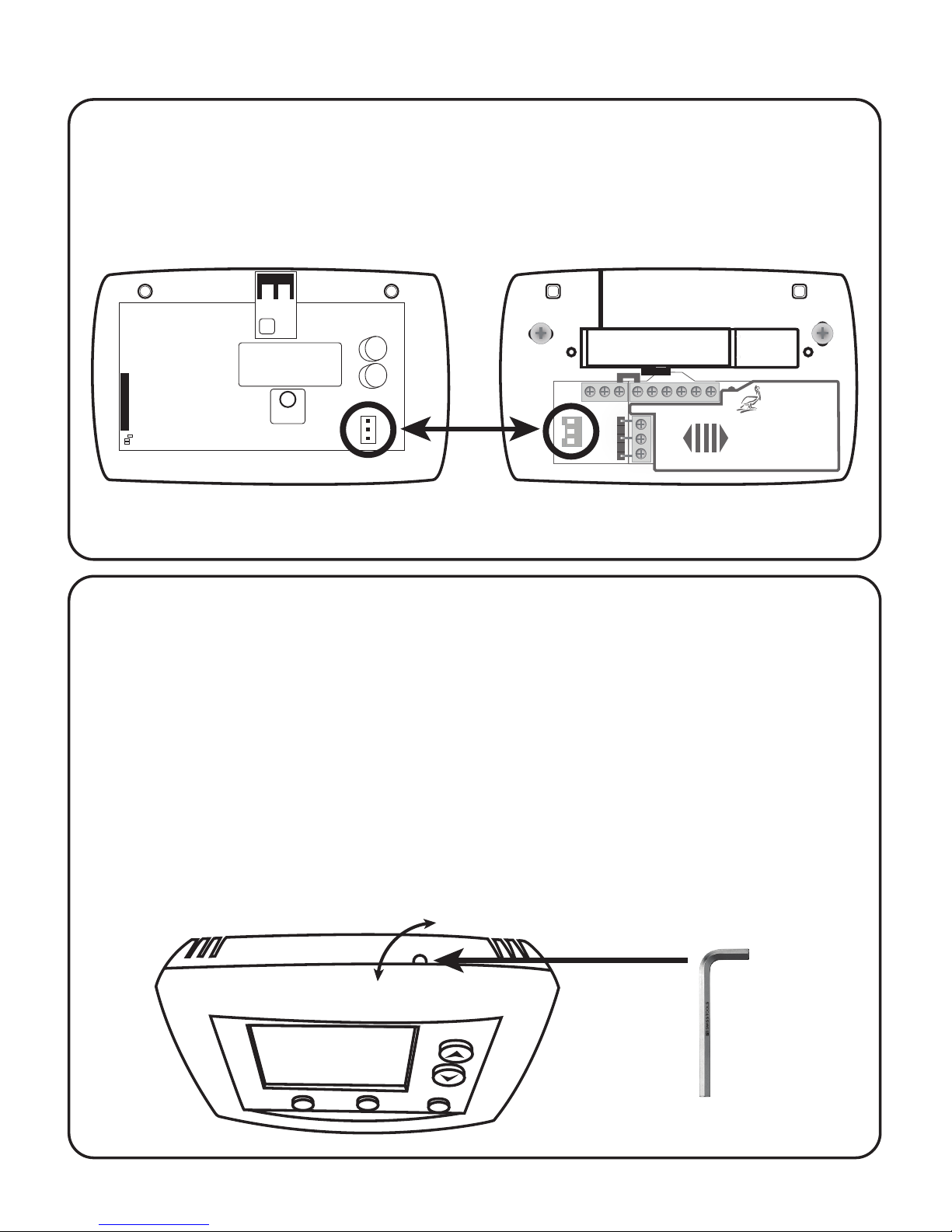
Align three pin connector from thermostat front cover to
three pin connector on rear cover. Push front cover onto
rear cover until secure.
Thermostat Front Cover Thermostat Rear Cover
Rc
CD R
R
C
D
Y W G W Y2 2
Pelican
Wireless Systems
Wiring Module
Model: WM500
Power: 24-30 VAC
PelicanWireless.com
Pelican Wilreless Systems
U
L
LISTED
ENERGY MGMT EQPT
E471330
3
3
TS200 Mounting and Assembly
The thermostat contains an internal locking mechanism to secure the
front cover to the rear cover. This is intended to keep untrained
individuals from tampering with the power and thermostat wire.
To engage the lock, assemble the thermostat and insert a 7/64" Allen
wrench (not included) into the key hole on the top of the thermostat.
Rotate clockwise until reaching the stop to secure. Rotate
counter-clockwise until reaching the stop to release.
7/64" Allen wrench
unlock rotation
lock rotation
Optional Tamper Resistant Lock
4
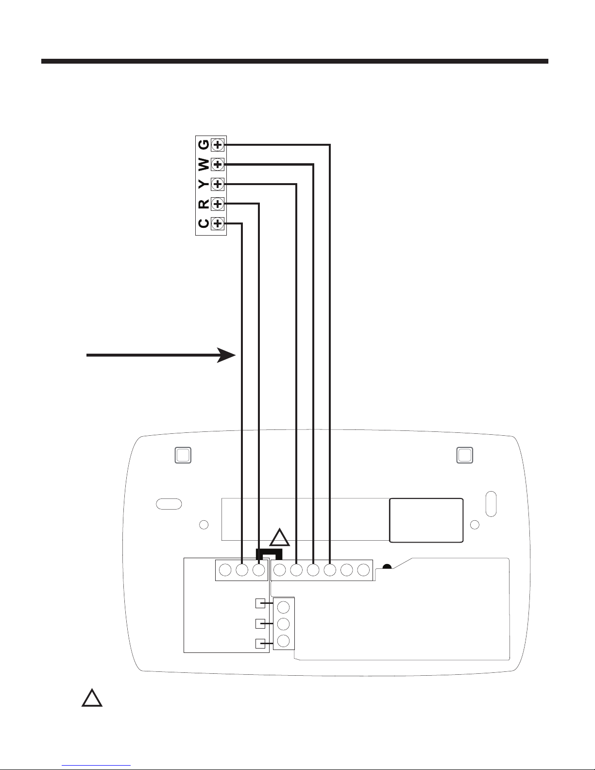
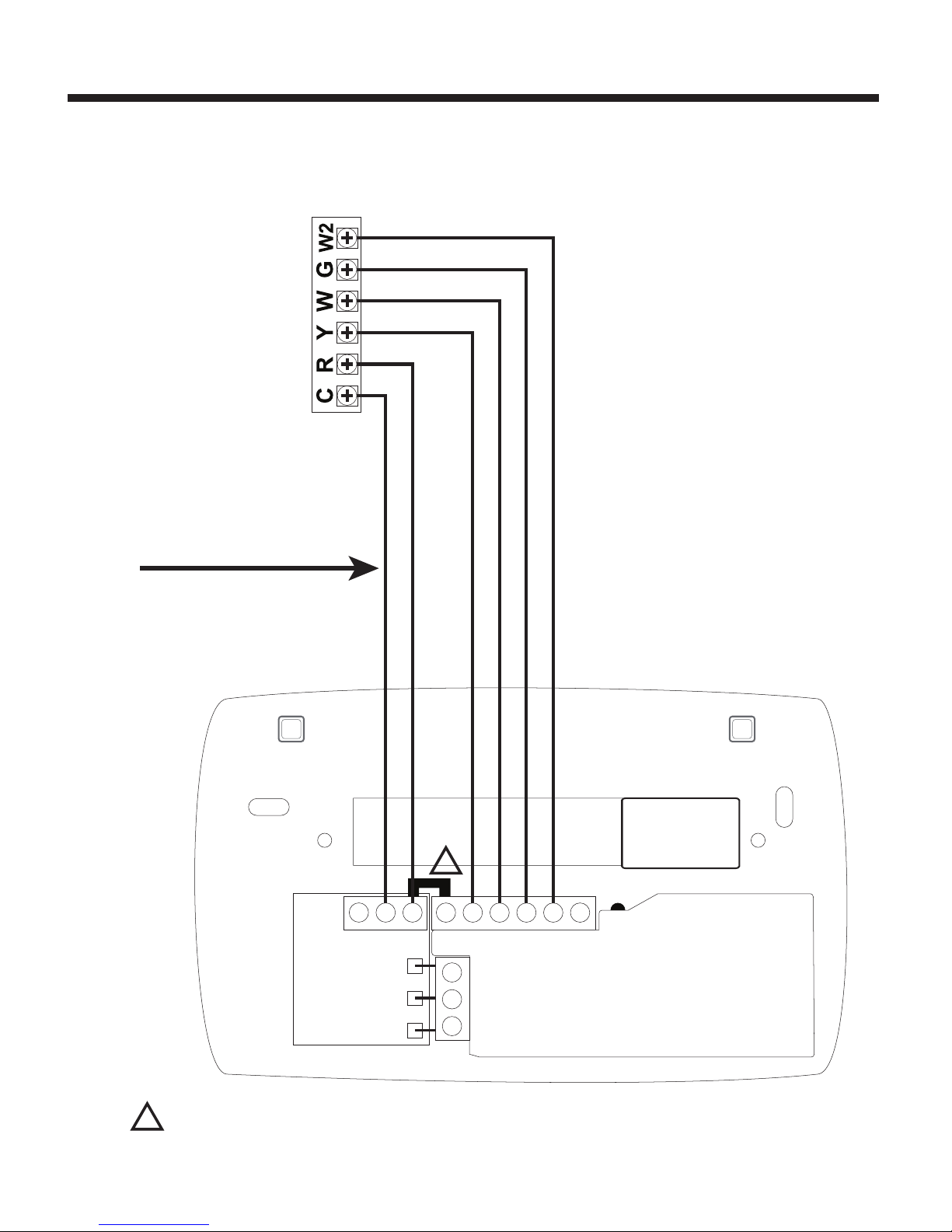
Conventional Wiring Guide
CD R Rc Y W G W2 Y2
Fan Circuit
Heat Circuit
Compressor Relay
24 VAC Power
24 VAC Common
Use 18 gauge unshielded
cable from thermostat to
the equipment.
1
5 Wire, 24VAC Conventional 1 stage cooling with
1 stage heat
1
For a Two Transformer System – remove jumper between R and Rc.
Connect the 24VAC power for energizing the unit’s Compressor to
thermostat’s (R) terminal. Connect second 24VAC power to
thermostat’s (Rc) terminal.
5
6 Wire, 24VAC Conventional 1 stage cooling with
2 stage heat
CD R Rc Y W G W2 Y2
2nd Stage Heat Circuit
Fan Circuit
1st Stage Heat Circuit
Compressor Relay
24 VAC Power
24 VAC Common
1
Conventional Wiring Guide
Use 18 gauge unshielded
cable from thermostat to
the equipment.
1
For a Two Transformer System – remove jumper between R and Rc.
Connect the 24VAC power for energizing the unit’s Compressor to
thermostat’s (R) terminal. Connect second 24VAC power to
thermostat’s (Rc) terminal.
 Loading...