

Pelican TCM1 Installation Manual
Pelican Wireless Systems, 2655 Collier Canyon Rd. Livermore, CA 94551
Phone: 888.512.0490
Email: support@pelicanwireless.com Website: www.pelicanwireless.com
Zoned Damper Control
Pelican
Wireless Systems
Installation Guide

Table of Contents
2
Damper Controller Options
Application and Communication
Thermostat Wired to Damper Actuator
Thermostat Terminal Designations
Thermostat Mounting
Limited Wire Installation
Thermostat Installation
Thermostat Wiring Diagrams
Power-Open, Spring-Return Actuator
Power-Closed, Spring-Return Actuator
Power-Open, Power-Closed or Floating Actuator
Dual Power-Open, Spring-Return Actuators
Dual Power-Closed, Spring-Return Actuators
Dual Power-Open, Power-Closed or Floating Actuators
Reheat: ON/OFF or Power-Open, Spring-Return Valve Motor
Reheat: Power-Open, Power Closed or Floating Valve Motor
Wireless Damper Control and Remote Thermostat
TCM1 Terminal Designations
TCM1 Mounting
TCM1 Wireless Communication with Remote Thermostat
TCM1 Installation
TCM1 Wiring Diagrams
Power-Open, Spring-Return Actuator
Power-Closed, Spring-Return Actuator
Power-Open, Power-Closed or Floating Actuator
Dual Power-Open, Spring-Return Actuators
Dual Power-Closed, Spring-Return Actuators
Dual Power-Open, Power-Closed or Floating Actuators
Reheat: ON/OFF or Power-Open, Spring-Return Valve Motor
Reheat: Power-Open, Power Closed or Floating Valve Motor
Configuration
3
4
8
9
10
10
11
12
12
13
13
14
14
15
15
16
17
18
19
20
21
21
22
22
23
23
24
24
25

Damper Controller Options
CHOOSING THE CORRECT DAMPER CONTROLLER FOR EACH
ZONE...
The Pelican solution is comprised of a Pelican zone controller residing at the HVAC
equipment and multiple Pelican zone damper controllers installed around the building.
Communication between the zone controller to the zone damper controllers are through
Pelican’s self-healing wireless mesh network.
There are two zone damper control options:
In cases where wire can easily be ran or already exists between the damper actuator and
thermostat, a Pelican 24VAC powered thermostat can be installed in the conditioned
space and directly wired to the damper actuator. As shown in:
● Figure 1.1 – 24VAC Powered Thermostat Wired Directly to a Single Damper
Actuator
● Figure 1.2 – 24VAC Powered Thermostat Wired Directly to Two Damper
Actuators
Proceed to Page 8 for further information on this option.
In cases where wire is unable to be ran from the damper actuator into the conditioned
space, a Pelican 24VAC damper actuator controller (TCM1) can be installed at the
actuator and a Pelican Remote Wireless Sensor can be installed in the conditioned
space. The TCM1 and Remote Wireless Sensor communicate wirelessly between each
other. As shown in:
● Fig. 2.1 – 24VAC Damper Actuator Controller (TCM1) Wireless Communication
to a Remote Thermostat for Single Damper Actuator Control
● Fig. 2.2 – 24VAC Damper Actuator Controller (TCM1) Wireless Communication
to a Remote Thermostat for Two Damper Actuator Control
Proceed to Page 16 for further information on this option.
3
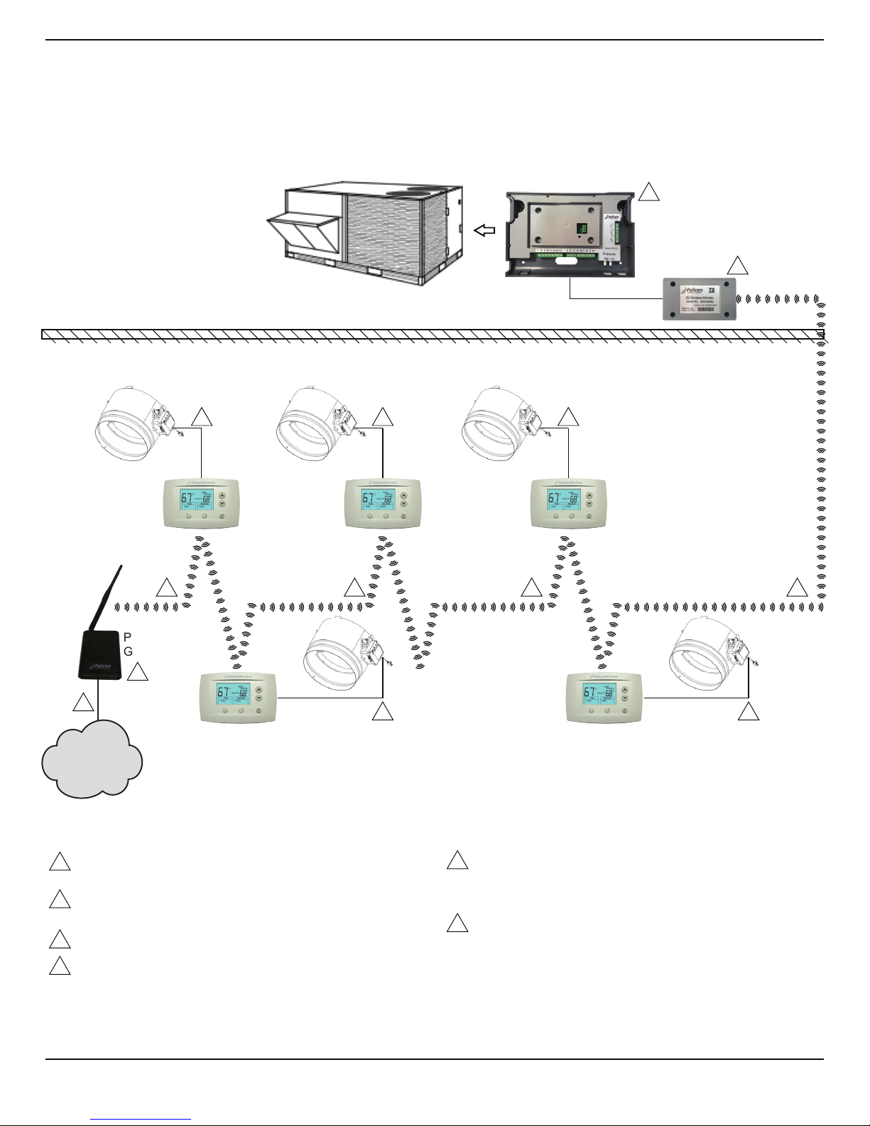
Fig. 1.1 – 24VAC Powered Thermostat Wired Directly to Single Damper Actuator
Rooftop
Pelican RTU Controller
Pelican
Wireless
Antenna
24VAC
Pelican
Thermostat
Pelican
Gateway
24VAC
Pelican
Thermostat
24VAC
Pelican
Thermostat
24VAC
Pelican
Thermostat
24VAC
Pelican
Thermostat
single duct
damper
single duct
damper
single duct
damper
single duct
damper
single duct
damper
Internet
2
4 4
444
1 111
3
4
5
6
2
3
4
5
6
COMMUNICATION ACROSS PELICAN SELF-HEALING WIRELESS
MESH NETWORK (IEEE 802.15.4).
ONE PELICAN GATEWAY CAN COMMUNICATE WITH UP TO 2000
PELICAN DEVICES.
HARDWIRED ETHERNET CONNECTION TO PELICAN GATEWAY.
INTERNET ENABLED THERMOSTAT IS WIRED TO ONE 24VAC
ZONE ACTUATOR.
1
WIRELESS ANTENNA FROM PELICAN ZONE CONTROLLER.
ANTENNA CAN BE INSTALLED ABOVE OR BELOW ROOF LINE
DEPENDING ON INSTALLATION ENVIRONMENTS AND WIRELESS
COMMUNICATION REQUIREMENTS.
PELICAN ZONE CONTROLLER. CAN BE INSTALLED ABOVE OR
BELOW ROOF LINE DEPENDING ON INSTALLATION
ENVIRONMENTS.
Rooftop
24VAC
Pelican
Thermostat
24VAC
Pelican
Thermostat
24VAC
Pelican
Thermostat
24VAC
Pelican
Thermostat
24VAC
Pelican
Thermostat
cold duct
damper
hot duct
damper
actuator
control
wire
cold duct
damper
hot duct
damper
actuator
control
wire
cold duct
damper
hot duct
damper
cold duct
damper
hot duct
damper
cold duct
damper
hot duct
damper
24VAC
Pelican
Thermostat
Pelican RTU Controller
Cold Deck
Pelican
Wireless
Antenna
Pelican RTU Controller
Hot Deck
Pelican
Wireless
Antenna
1 111
44
4 4 4
Pelican
Gateway
Internet
2
3
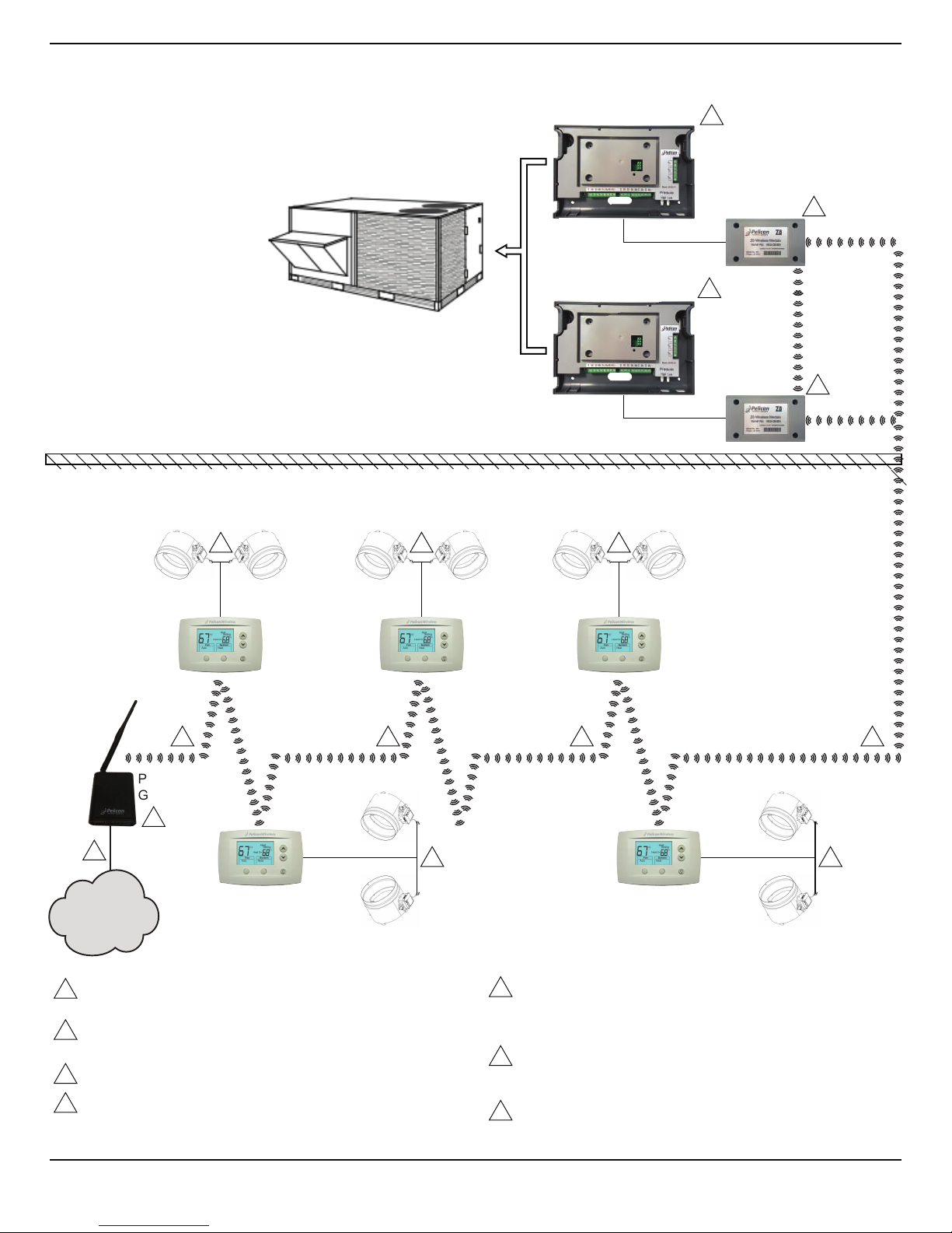
Fig. 1.2 – 24VAC Powered Thermostat Wired Directly to Two Damper Actuators
Pelican
Wireless
Antenna
5
2
3
4
5
6
7
COMMUNICATION ACROSS PELICAN SELF-HEALING WIRELESS
MESH NETWORK (IEEE 802.15.4).
ONE PELICAN GATEWAY CAN COMMUNICATE WITH UP TO 2000
PELICAN DEVICES.
HARDWIRED ETHERNET CONNECTION TO PELICAN GATEWAY.
INTERNET ENABLED THERMOSTAT IS WIRED TO TWO ZONE
ACTUATORS.
1
WIRELESS ANTENNA FROM PELICAN ZONE CONTROLLER.
ANTENNA CAN BE INSTALLED ABOVE OR BELOW ROOF LINE
DEPENDING ON INSTALLATION ENVIRONMENTS AND WIRELESS
COMMUNICATION REQUIREMENTS.
PELICAN COLD DECK ZONE CONTROLLER. CAN BE INSTALLED
ABOVE OR BELOW ROOF LINE DEPENDING ON INSTALLATION
ENVIRONMENTS.
PELICAN HOT DECK ZONE CONTROLLER. CAN BE INSTALLED
ABOVE OR BELOW ROOF LINE DEPENDING ON INSTALLATION
ENVIRONMENTS.
5
5
6
7
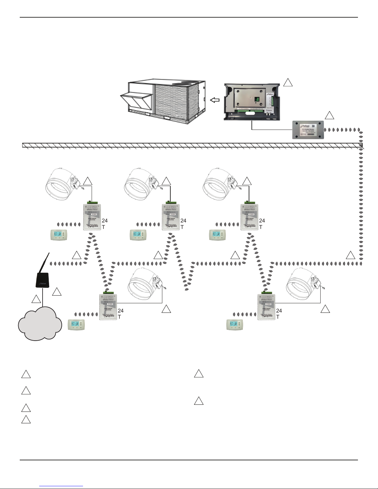
Fig. 2.1 – 24VAC Damper Actuator Controller (TCM1) Wireless Communication to
a Remote Thermostat for Single Damper Actuator Control
Rooftop
Pelican RTU Controller
Pelican
Wireless
Antenna
24VAC
TCM1
RT1
24VAC
TCM1
RT1
24VAC
TCM1
24VAC
TCM1
24VAC
TCM1
single duct
damper
single duct
damper
single duct
damper
single duct
damper
single duct
damper
1 111
Pelican
Gateway
Internet
2
3
4 4
444
6
6
5
2
3
4
5
6
COMMUNICATION ACROSS PELICAN SELF-HEALING WIRELESS
MESH NETWORK (IEEE 802.15.4).
ONE PELICAN GATEWAY CAN COMMUNICATE WITH UP TO 2000
PELICAN DEVICES.
HARDWIRED ETHERNET CONNECTION TO PELICAN GATEWAY.
INTERNET ENABLED TCM1 IS WIRED TO ONE ZONE ACTUATOR.
RT1 REMOTE SENSOR COMMUNICATES TO TCM1 THROUGH
WIRELESS MESH NETWORK.
1
WIRELESS ANTENNA FROM PELICAN ZONE CONTROLLER.
ANTENNA CAN BE INSTALLED ABOVE OR BELOW ROOF LINE
DEPENDING ON INSTALLATION ENVIRONMENTS AND WIRELESS
COMMUNICATION REQUIREMENTS.
PELICAN ZONE CONTROLLER. CAN BE INSTALLED ABOVE OR
BELOW ROOF LINE DEPENDING ON INSTALLATION
ENVIRONMENTS.
RT1 RT1 RT1
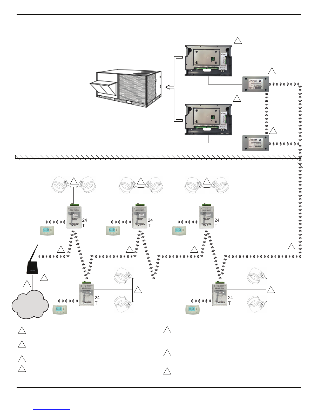
Fig. 2.2 – 24VAC Damper Actuator Controller (TCM1) Wireless Communication to
a Remote Thermostat for Two Damper Actuator Control
Rooftop
cold duct
damper
hot duct
damper
cold duct
damper
hot duct
damper
cold duct
damper
hot duct
damper
cold duct
damper
hot duct
damper
Pelican RTU Controller
Cold Deck
Pelican
Wireless
Antenna
Pelican RTU Controller
Hot Deck
Pelican
Wireless
Antenna
24VAC
TCM1
24VAC
TCM1
24VAC
TCM1
24VAC
TCM1
cold duct
damper
hot duct
damper
24VAC
TCM1
1
1
11
44
4 4 4
Pelican
Gateway
Internet
2
3
7
5
5
6
7
RT1 RT1
RT1 RT1 RT1
2
3
4
5
6
7
COMMUNICATION ACROSS PELICAN SELF-HEALING WIRELESS
MESH NETWORK (IEEE 802.15.4).
ONE PELICAN GATEWAY CAN COMMUNICATE WITH UP TO 2000
PELICAN DEVICES.
HARDWIRED ETHERNET CONNECTION TO PELICAN GATEWAY.
INTERNET ENABLED TCM1 IS WIRED TO TWO ZONE ACTUATORS.
RT1 REMOTE SENSOR COMMUNICATES TO TCM1 THROUGH
WIRELESS MESH NETWORK.
1
WIRELESS ANTENNA FROM PELICAN ZONE CONTROLLER.
ANTENNA CAN BE INSTALLED ABOVE OR BELOW ROOF LINE
DEPENDING ON INSTALLATION ENVIRONMENTS AND WIRELESS
COMMUNICATION REQUIREMENTS.
PELICAN COLD DECK ZONE CONTROLLER. CAN BE INSTALLED
ABOVE OR BELOW ROOF LINE DEPENDING ON INSTALLATION
ENVIRONMENTS.
PELICAN HOT DECK ZONE CONTROLLER. CAN BE INSTALLED
ABOVE OR BELOW ROOF LINE DEPENDING ON INSTALLATION
ENVIRONMENTS.

Thermostat Wired to Damper Actuator
WHEN INSTALLING THIS PRODUCT...
1. Read these instructions carefully and thoroughly. Failure to follow these instructions or a result
of improper installation, service, adjustments, maintenance, and/or use can result in personal
injury, damage to personal property, and/or cause a hazardous and dangerous situation.
2. Check the ratings and description given in the specification of the product to make sure the
product is suitable for your application
3. Installer must be trained and experienced service technician. Follow all safety codes and
regulations and all local and state building codes. Read instructions thoroughly and follow any
warnings or notes.
4. After installation is complete, check product operation as provided in these instructions.
CAUTION
1. Disconnect power supply before connecting any wiring to device to prevent
electrical shock or damage to equipment.
2. This guide is designed for certified, trained, and experienced service technicians.
Failure to follow installation instructions does not alleviate installer responsibility to
protect the equipment, the property, and the device it is being connected too. If at
anytime if there is concern or confusion about how to install this device, immediately
stop what you are doing and either contact Pelican Wireless Systems or a certified
Pelican Wireless Systems distributor.
WARNING
1. This equipment is designed to communicate over radio frequency to other Pelican
equipment only. If this equipment is not installed and used in accordance with the
instruction manual, you may experience wireless interference. This device has been
tested and complies with FCC rules and regulations.
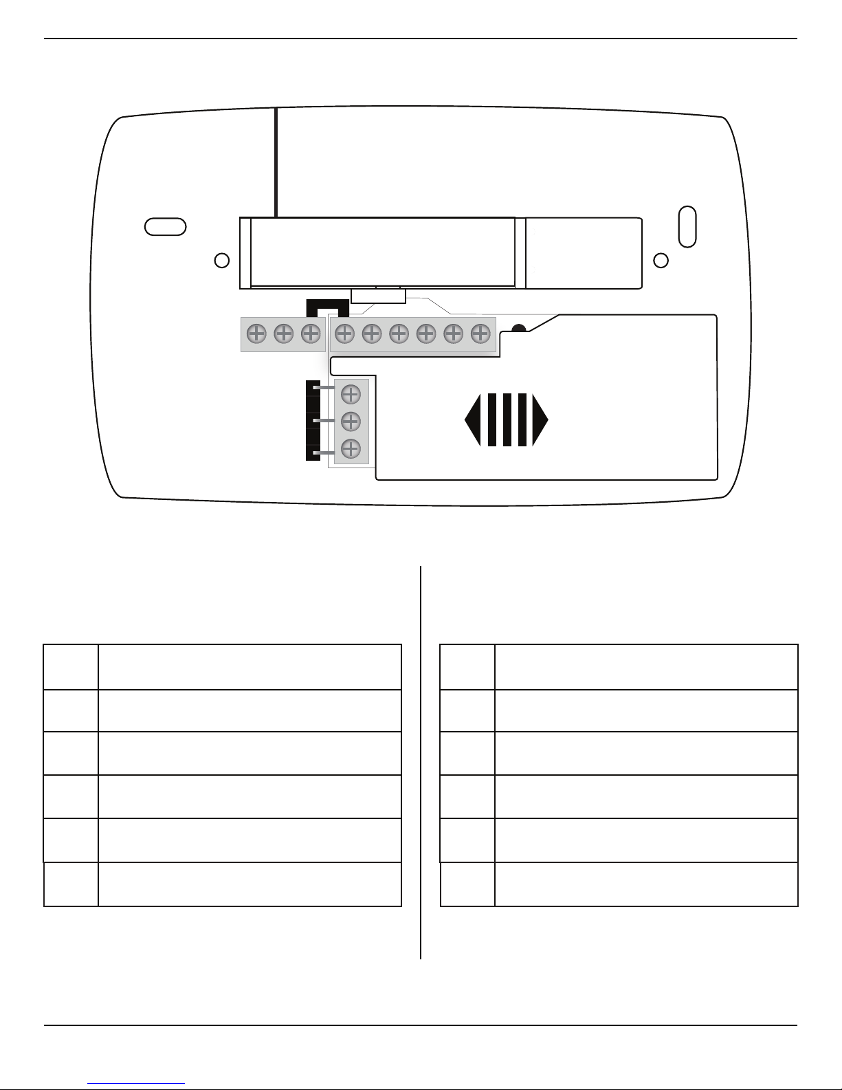
LOCATION AND MOUNTING
Choose a location for the Pelican zone thermostat that represents that spaces temperature, and
where connections are accessible. The zone thermostat is directly wired to the damper actuator.
8
Rc
CD R
R
C
D
Y W G W Y2 2Rc
CD R
R
C
D
Y W G W Y2 2
SINGLE DUCT
C
R
Y
Y2
W2
W
Common 24VAC
24VAC Reheat Power Open or On
24VAC Reheat Power Close
24VAC Power
24VAC Damper Power Close
24VAC Damper Power Open
DUAL DUCT
C
R
Y
Y2
W2
W
Common 24VAC
24VAC Heat Damper Power Open
24VAC Heat Damper Power Close
24VAC Power
24VAC Cold Damper Power Close
24VAC Cold Damper Power Open
Fig. 3.1 – Pelican 24 VAC Thermostat Terminal Designations
9
 Loading...