


USER GUIDE
Flat Bed
Foil Printer
Version 2.21 August 2019
Flat Bed Foil Printer PC Tool version 1.2.x.0
Firmware version 2.47

Flat Bed Foil Printer User Guide
1
TABLE OF CONTENTS
1 ABOUT THIS MANUAL ............................................................................................................................................................... 8
2 ABOUT FLAT BED FOIL PRINTER...................................................................................................................................... 9
2.1 Introduction ........................................................................................................................................................................... 9
2.2 Specifications ...................................................................................................................................................................... 10
2.2.1 Technical specifications ............................................................................................................................... 10
2.2.2 Software specifications .................................................................................................................................. 11
2.2.3 User related and other specifications................................................................................................. 11
3 GETTING STARTED ..................................................................................................................................................................... 12
3.1 Unboxing ............................................................................................................................................................................... 12
3.2 What’s Inside? .................................................................................................................................................................... 13
3.3 Setting Up The Flat Bed Foil Printer ................................................................................................................. 14
4 FOIL HANDLING .......................................................................................................................................................................... 18
4.1 About The Foil .................................................................................................................................................................... 18
4.2 Specifications Per Group ........................................................................................................................................... 20
4.3 How To Insert The Foil ................................................................................................................................................. 22
4.4 How To Remove The Foil .......................................................................................................................................... 23
5 FLAT BED FOIL PRINTER PC TOOL .............................................................................................................................. 24
5.1 Introduction ........................................................................................................................................................................ 24
5.2 What’s New From Version 1.2.0.0 ........................................................................................................................ 24
5.2.1 Key features ......................................................................................................................................................... 24
5.2.2 Printhead calibration .................................................................................................................................... 25
5.2.3 New foil groups ................................................................................................................................................. 25
5.2.4 New sensors ......................................................................................................................................................... 25
5.3 Software Installation ..................................................................................................................................................... 26
5.4 Launch Application ....................................................................................................................................................... 27
5.5 Creating A New Design .............................................................................................................................................. 28
5.5.1 Object Orientation .......................................................................................................................................... 29
5.5.2 Printing on Spine ............................................................................................................................................. 30
5.5.3 Parts of Printing Object ............................................................................................................................... 31
5.5.4 Print Areas .............................................................................................................................................................. 31
5.5.5 Print Margins ...................................................................................................................................................... 32
5.5.6 Design Toolbar ................................................................................................................................................... 33
5.5.7 Saving Design..................................................................................................................................................... 38
5.5.8 Inserting Text and Images ........................................................................................................................ 38
5.5.9 Selection, Movement and Alignment of Elements ................................................................. 41
5.5.10 Rotation of Elements .................................................................................................................................... 42
5.5.11 Foil Colour Layers ............................................................................................................................................. 42
Peleman Industries

Flat Bed Foil Printer User Guide
2
5.5.12 Rulers & Guidelines ........................................................................................................................................ 44
5.5.13 Multiple jobs ........................................................................................................................................................ 45
5.5.14 Design Zooming.............................................................................................................................................. 46
5.6 Open Design ..................................................................................................................................................................... 46
5.7 Print Design ....................................................................................................................................................................... 46
5.8 Tools .......................................................................................................................................................................................... 47
5.8.1 Settings ................................................................................................................................................................... 47
5.8.2 PELEMAN Products ....................................................................................................................................... 50
5.8.3 Check for Updates ........................................................................................................................................... 51
5.8.4 Request for Service ......................................................................................................................................... 52
5.8.5 Manage Templates ......................................................................................................................................... 52
5.8.6 Testing and Calibration ............................................................................................................................... 56
5.8.7 Service Menu ...................................................................................................................................................... 60
5.8.8 About the Foil Printer .................................................................................................................................. 60
5.8.9 Help Button .......................................................................................................................................................... 61
5.9 Uninstall ................................................................................................................................................................................. 62
5.9.1 Uninstallation Using Start Menu .......................................................................................................... 62
5.9.2 Uninstallation Using Control Panel .................................................................................................... 62
5.9.3 Uninstallation Using Installation Setup .......................................................................................... 63
6 MAINTENANCE ............................................................................................................................................................................ 64
6.1 Basic maintenance ....................................................................................................................................................... 64
6.1.1 Accessories .......................................................................................................................................................... 64
6.2 Advanced maintenance ............................................................................................................................................ 65
6.2.1 Advanced maintenance by technician ........................................................................................... 65
7 TROUBLESHOOTING .............................................................................................................................................................. 67
7.1 Troubleshooting Bad Print Result ..................................................................................................................... 67
7.2 Troubleshooting – Foil Is Not Spinning .......................................................................................................... 67
7.3 Troubleshooting – Calibration ............................................................................................................................... 68
7.4 Troubleshooting – Errors ........................................................................................................................................... 69
7.4.1 No communication with the printer error/printer not connected ............................ 69
7.4.2 Printer is damaged error ............................................................................................................................ 69
7.4.3 Head error ............................................................................................................................................................. 70
7.4.4 Dots damaged error ...................................................................................................................................... 70
7.4.5 Driver installation ............................................................................................................................................. 70
8 SHIPPING AND TRANSPORTATION .............................................................................................................................. 71
9 FREQUENTLY ASKED QUESTIONS (FAQs) .............................................................................................................. 72
10 APPENDICES ................................................................................................................................................................................ 73
10.1 List of Keyboard Shortcuts ....................................................................................................................................... 73
10.2 Supported Template Dimensions...................................................................................................................... 75
Peleman Industries

Flat Bed Foil Printer User Guide
3
10.2.1 Type 1a and 1b ..................................................................................................................................................... 76
10.2.2 Type 2a ..................................................................................................................................................................... 77
10.3 Built-in Printing Settings for Foils and Materials .................................................................................... 78
10.4 Custom material grid ................................................................................................................................................. 80
10.5 Default Template Specifications ......................................................................................................................... 82
10.5.1 Preset Margins ................................................................................................................................................... 82
10.5.2 Factory Set ............................................................................................................................................................ 82
10.6 What’s new .......................................................................................................................................................................... 85
10.6.1 Version 1.0.0.63 ................................................................................................................................................... 85
10.6.2 Version 1.0.2.0 ...................................................................................................................................................... 85
10.6.3 Version 1.1.0.0 ....................................................................................................................................................... 85
10.6.4 Version 1.2.0.0 ...................................................................................................................................................... 86
10.7 Parts and Accessories List ........................................................................................................................................ 86
Peleman Industries

Flat Bed Foil Printer User Guide
4
TABLE OF FIGURES
Figure 1: Flat Bed Foil Printer with Cover Placed to Print .................................................................................... 8
Figure 2: Printed Design Examples ...................................................................................................................................... 9
Figure 3: Cut Binding Strips ...................................................................................................................................................... 12
Figure 4: Unpackaging ................................................................................................................................................................. 13
Figure 5: Flat Bed Foil Printer Package Contents ................................................................................................... 14
Figure 6: Lock Tool and Support Removal ..................................................................................................................... 15
Figure 7: Flat Bed Foil Printer Connections .................................................................................................................. 15
Figure 8: Use Supplied Underlay Materials for Different Applications .................................................... 16
Figure 9: Different possibilities to use double paper clamp to hold the substrate ......................... 17
Figure 10: Connecting the Coils ............................................................................................................................................. 22
Figure 11: Foil Inserted in fead of Flat Bed Foil Printer ......................................................................................... 23
Figure 12: Files Required for Installation ........................................................................................................................ 26
Figure 13: Available Options in All Programmes of Start Menu for Launching Application .... 27
Figure 14: Flat Bed Foil Printer PC Tool ........................................................................................................................... 27
Figure 15: New Design Startup Dialog Box for Selection of Template .................................................... 28
Figure 16: Display for Selection of Appropriate Template & Associated object Orientation ... 28
Figure 17: Design Window Based on Selected Template and Object Placement ......................... 29
Figure 18: Vertical Spine Orientation (Left) and Horizontal Spine Orientation (Right) ............... 30
Figure 19: Vertical Spine Orientation (Left) and Horizontal Spine Orientation (Right) ................. 31
Figure 20: Margins (grey zone around the template) .......................................................................................... 32
Figure 21: Design Toolbar ........................................................................................................................................................... 33
Figure 22: Design Toolbar Group 1 - Functions .......................................................................................................... 33
Figure 23: Design Toolbar Group 2 - Tools .................................................................................................................... 34
Figure 24: Design Toolbar Group 3 – Edit Functions ............................................................................................ 34
Figure 25: Design Toolbar Group 4 - Text Editing.................................................................................................... 35
Figure 26: Design Toolbar Group 5 - Element Alignment ................................................................................ 36
Figure 27: Design Toolbar Group 6 - Rotation Degree ........................................................................................ 36
Figure 28: Design Toolbar Group 7 – XY Coordinates ........................................................................................... 37
Figure 29: Design Toolbar Group 8 – Make Database .......................................................................................... 37
Figure 30: Text box placed in a print area containing the text “My Photos”....................................... 38
Figure 31: Image Thresholding Menu .............................................................................................................................. 39
Figure 32: Image of palm tree placed inside print area ..................................................................................... 40
Figure 33: Layer Window ........................................................................................................................................................... 43
Figure 34: Rulers and Guidelines for Alignment ..................................................................................................... 44
Figure 35: Zoom Slider & Buttons ....................................................................................................................................... 46
Figure 36: Application Settings Tab in Available Tools ........................................................................................ 47
Figure 37: Units Setting for Rulers in Tools .................................................................................................................. 47
Figure 38: Ruler Display Setting in Tools ....................................................................................................................... 48
Figure 39: Snap Setting in Tools ........................................................................................................................................... 48
Figure 40: Setting in Tools for Automatic Search for Updates ..................................................................... 48
Figure 41: Setting in Tools to Enable All Flat Bed Foil Printer Messages ............................................... 48
Figure 42: Setting in Tools to Customise Printing Parameters .................................................................... 48
Figure 43: Settings for Printing Parameters ............................................................................................................... 49
Figure 44: Setting in Tools for Transportation ........................................................................................................... 50
Figure 45: Settings in Tools for Smart Temperature Control ......................................................................... 50
Figure 46: Settings in Tools for Printhead Calibration ........................................................................................ 50
Figure 47: Tools to Check for Updates .............................................................................................................................. 51
Figure 48: Warning Message if Printer is Not Connected ................................................................................. 51
Figure 49: Warning Message if Not Connected to Server ................................................................................. 52
Figure 50: Screen for Managing Templates ................................................................................................................. 53
Peleman Industries

Flat Bed Foil Printer User Guide
5
Figure 51: Warning Message at Start of Creating New Template ................................................................ 53
Figure 52: Screen for Selecting Type of New Template ...................................................................................... 54
Figure 53: Screen for Inserting Dimensions of New Template ..................................................................... 54
Figure 54: Screen for Inserting Dimensions of Window in New Template .......................................... 55
Figure 55: Screen for Selecting Material, Softness and Name of New Template ............................. 55
Figure 56: Calibrate Printhead tab ..................................................................................................................................... 56
Figure 57: Calibration Start Screen ..................................................................................................................................... 57
Figure 58: Torque Sensor Test ............................................................................................................................................... 58
Figure 59: Service Menu in Tools ......................................................................................................................................... 60
Figure 60: About Flat Bed Foil Printer............................................................................................................................. 60
Figure 61: Built-In Software Help .......................................................................................................................................... 61
Figure 62: Uninstall Option in Start Menu .................................................................................................................... 62
Figure 63: Uninstall Options in Control Panel ........................................................................................................... 63
Figure 64: Uninstall Option in Software Installation Setup ............................................................................. 63
Figure 65: Printer Statistics ...................................................................................................................................................... 64
Figure 66: SPUP0000134 - Head plate for Z-axis subassembly – GEN 2 ................................................ 65
Figure 67: Attach the locking tool and add cardboard supports.................................................................. 71
Figure 68: Dimensions of Double Side Cover with Window .......................................................................... 76
Figure 69: Dimensions of Single Side Cover ............................................................................................................... 77
Peleman Industries

Flat Bed Foil Printer User Guide
6
LIST OF TABLES
Table 1: Compatible versions of software and firmware ........................................................................................ 11
Table 2: Foil Colours ........................................................................................................................................................................ 18
Table 3: Specifications and Indications of Foil Groups ........................................................................................ 20
Table 4: Keyboard Shortcuts .................................................................................................................................................... 73
Table 5: Settings for group A: Gold, Silver, Red and Blue Foils ...................................................................... 78
Table 6: Settings for group B: Gold, Silver, Red and Blue Foils ...................................................................... 78
Table 7: Settings for group C: Gold and Silver Foils for Offset Sheet ........................................................ 78
Table 8: Settings for group D: Black Foil ........................................................................................................................ 79
Table 9: Settings for group E White Foil......................................................................................................................... 79
Table 10: Custom Material Grid ............................................................................................................................................. 80
Table 11: Factory template dimensions ........................................................................................................................... 82
Peleman Industries

Flat Bed Foil Printer User Guide
7
Peleman Industries

Flat Bed Foil Printer User Guide
8
1 ABOUT THIS MANUAL
This guide summarises the basic know-how required to install and operate the Flat Bed
Foil Printer and its associated Flat Bed Foil Printer PC Tool utility applications of the latest
versions starting from 1.2.0.0.
Visit our websites to download previous versions of the software like 1.0.0.63, with
associated user guide: https://flatbedfoilprinter.com/ or https://webshop.peleman.com/en-
be/machine/unifoilprinter
This manual is divided into sections based on the different subject matters to provide users
with all the necessary information in an easily accessible way.
• Section 2: Introduction of the Flat Bed Foil Printer
• Section 3: Information required to setup the printer and start working
• Section 4: Details of the foils
• Section 5: Basics of the software utility application
• Section 6: Maintenance
• Section 7: Troubleshooting
• Section 8: Shipping and transportation
• Section 9: Frequently asked questions (FAQs)
• Section 10: Appendices for additional information
Figure 1: Flat Bed Foil Printer with Cover Placed to Print
Peleman Industries

Flat Bed Foil Printer User Guide
9
2 ABOUT FLAT BED FOIL PRINTER
2.1 Introduction
The Flat Bed Foil Printer allows you to personalise your books, notebooks, agendas,
contracts and more. If you are about to present an offer, a contract or even yourself in a
meeting, with the Flat Bed Foil Printer your work always stands out.
Flat Bed Foil Printer is an innovative digital printer that prints text and images with foil
directly from a digital file on almost any flat and smooth material like paper, plastic as well
as laminated cardboard materials. Designs are being created in the PC Tool application
provided by Unibind Manufacturing Ltd.
Peleman Industries
Figure 2: Printed Design Examples

Flat Bed Foil Printer User Guide
10
2.2 Specifications
2.2.1 Technical specifications
• Weight: 25 kg
• Size of machine: L: 615mm x W: 503mm x H: 295mm / in ‘home’ position L: 690mm
• Printer table dimensions: 600 mm x 310 mm
• Printable area: 450 mm x 300 mm [older versions: 410 mm x 280 mm]
• Active printhead area (strokes of): 57 mm
• Resolution: 300 x 300 dpi
• Speed: up to 2,5 cm/sec (1 inch/sec)
• Connection to computer with USB 2.0 (shielded)
• Electrical consumption: max. 72 Watt
Peleman Industries

Flat Bed Foil Printer User Guide
11
Software
Firmware
1.0.0.57 or 1.0.0.63
2.11 or 2.14 or 2.17
1.0.2.0 or 1.1.0.0. or 1.1.1.0
2.17 or 2.28 or 2.32
1.2.0.0
2.41, 2.47 or up
2.2.2 Software specifications
• Operating systems for software version 1.0.0.63: Windows XP, Vista, Windows 7
• Operating systems for software version 1.0.2.0: Windows XP, Vista, Windows 7
• Operating systems for software version 1.1.x.0: Windows 7, Windows 8, Windows 10
o Early versions of software can in some cases be installed on latest Windows versions with turned
off driver signature enforcement.
o Latest versions can in some cases be installed on early Windows versions - not fully supported.
• Operating systems for software version 1.2.x.0: Windows 10
o off driver signature enforcement.
o Latest versions can in some cases be installed on early Windows versions - not fully supported.
• Maximum template size: 480 mm x 480 mm
• Importable file formats: PDF, JPG, TIFF, PNG, GIF, BMP
• Software and firmware compatibility (it is highly recommended to not update
software, firmware or O.S. when versions are not compatible).
Table 1: Compatible versions of software and firmware
2.2.3 User related and other specifications
• Spine supports included (for printing on spines)
• Total foil length: 100 m
• Different foil colours: red, blue, silver, gold, white, black
(For more information and detailed foil features, please refer to the paragraph about
the available foil options.)
Peleman Industries

Flat Bed Foil Printer User Guide
12
Tip: Scan the QR code to access
the demonstrational video
Figure 3: Cut Binding Strips
3 GETTING STARTED
3.1 Unboxing
Flat Bed Foil Printer is delivered in a wooden box. The box is very heavy, please pay
attention and use a transporter or at least the help of one extra person.
After transportation to the selected location, open the box by cutting the binding strips as
shown in figure 3.
First, lift the lid, after that you can remove the cardboard sheets from between the buffers.
Continue by lifting the wooden box up. Now you can remove protective buffers. Make sure
you have space on the table where you wish to place the Flat Bed Foil Printer. Machine to
be moved by two persons. Make sure that the Flat Bed Foil Printer is placed firmly on a
desk. Remove the plastic bag.
Peleman Industries

Flat Bed Foil Printer User Guide
13
Figure 4: Unpackaging
• Flat Bed Foil Printer
• Powercable (1 of below)
EU = UFPRELEC018;
UK = UFPRELEC020;
US = UFPRELEC019
• Power supply UFPRELEC012
• USB cable UFPRELEC015
• Foil Gold UFPR0000002
• User guide SPUP0000103
• Quickguide SPUP0000104
• Lock removal instructions SPUP0000107
• Screwdriver SPUP0000111
• Spine support set (UFPRSUP0002 +3 +4 +5)
• Empty core UFPR0000005
• USB drive Flat Bed Foil Printer SPUP0000144
• Paper ring SPUP0000142
• Lock X-axis SPUP0000097
• 4x screw with cross head SPUP0000028
• Rubber/foam pad SPUP0000046
• Polycarbonate plate SPUP0000130
• Double paper clamp UFPR0000021 (NEW 2019)
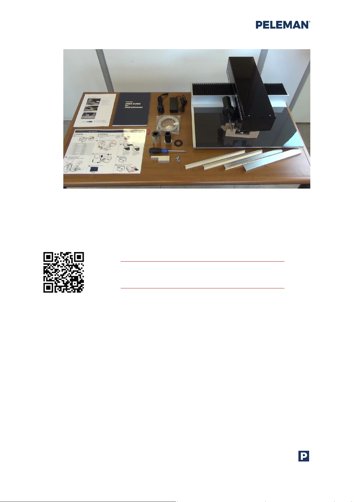
3.2 What’s Inside?
List of content (regular version):
Attention! Do not throw away accessories like the polycarbonate plate and foam pad.
Contact your representative to (re)order any items.
Peleman Industries
Flat Bed Foil Printer User Guide
14
Figure 5: Flat Bed Foil Printer Package Contents
Tip: Scan the QR code to access
the demonstrational video
3.3 Setting Up The Flat Bed Foil Printer
Make sure you remove the ‘locking tool’ and supports first, before connecting the printer to
power supply. Remove the lock tool completely with supplied screwdriver. Do not lose
those items as they may be needed for transportation in the future. You can place the
machine back in transport position via Settings in software. Never transport the machine
without properly attaching locking tool.
Peleman Industries

Flat Bed Foil Printer User Guide
15
Figure 6: Lock Tool and Support Removal
Connect the Flat Bed Foil Printer to the computer with the provided USB cable. Make sure
your computer has a grounded connection to the power supply.
Attention! Make sure the printing table is clear of objects and the lock tool has
been removed.
Plug the power adapter into an electrical outlet to power the device. Printer will move to
‘home position’.
Open the installed software (see section below) to check if the printer is connected to your
computer.
Peleman Industries
Figure 7: Flat Bed Foil Printer Connections

Flat Bed Foil Printer User Guide
16
Depending on the medium that you will print on, use the acrylic plate or the foam pad. You
don’t need to remove one of the two completely. However, for some materials the result
will be better when only one of two is being used on the aluminium printing table.
The underlay materials (acrylic sheet and foam pad) give the best support for the most
known materials. Replace them for new on regular basis.
Use acrylic plate on top when printing on:
Smooth paper*, clear covers, flex covers and other bendable material. You also can use
acrylic plate to glue materials like leather with double sided tape sheets.
*Use extra paper sheets as underlay when printing on paper.
Use foam pad in top when working with:
Hard covers, thick acrylic sheets and other hard, stiff materials.
Figure 8: Use Supplied Underlay Materials for Different Applications
Peleman Industries

Flat Bed Foil Printer User Guide
17
Use double paper clamp
Recently we started to add a paper clamp in the package (item UFPR0000021). You can
use it to fasten your substrate. It can be used as a clamp to hold the substrate or as an end
stop to avoid covers from moving during printing.
Attention: be careful with printing near the edge. Printhead can touch the clamp and get
damaged.
Figure 9: Different possibilities to use double paper clamp to hold the substrate
Peleman Industries

Flat Bed Foil Printer User Guide
18
Picture
Item Code
New Name
Group
UFPR0000001
Metal Silver
A
UFPR0000002
Metal Gold
A
UFPR0000003
Metal Blue
A
UFPR0000004
Metal Red
A
UFPR0000018
Metal Silver
B
4 FOIL HANDLING
4.1 About The Foil
The foil is the original thermal transfer ribbon (TTR) for Flat Bed Foil Printer. Foils shown
below are used to print on covers and other materials.
To ensure that the Flat Bed Foil Printer works correctly, we recommend using only the
original foil. The printhead can be damaged when using by non-original foil, especially foils
for hot stamping.
Foils are categorised based on their features. Within the same group, the same settings can
be used for the foils.
Table 2: Foil Colours
Peleman Industries

Flat Bed Foil Printer User Guide
19
Picture
Item Code
New Name
Group
UFPR00000IG
Metal Gold
B
UFPR0000020
Metal Blue
B
UFPR0000019
Metal Red
B
UFPR0000012
Metal Silver
C
UFPR0000013
Metal Gold
C
UFPR0000006
Black
D
UFPR0000014
White
E
Peleman Industries

Flat Bed Foil Printer User Guide
20
Picture
Item Code
New Name
Group
UFPR0000005
Core
/
Group
A B C D E
Range of
application (only
for smooth
surfaces)
Writing paper/
cardboard
**
***
**
**
N/A
Coated paper
****
***
***
***
N/A
Uncoated paper
*
***
**
N/A
N/A
PVC
*****
***
***
***
****
ABS
****
N/A
****
N/A
N/A
PE
***
N/A
***
N/A
***
Extruded acrylic
****
N/A
***
****
N/A
Smooth leather
*****
N/A
N/A
N/A
N/A
Smooth metal
N/A
N/A
N/A
N/A
N/A
Smooth wood
N/A
N/A
N/A
***
N/A
4.2 Specifications Per Group
Below you will find specifications and indications for each group. You can use this as a
reference to decide which foil can be ordered for your specific needs.
Please note that there is a large variety of materials as well as material qualities. Therefore, it
is not possible to test all existing materials and material manufactures.
The list is being updated on a regular basis. Please feel free to contact us to share your
results.
Table 3: Specifications and Indications of Foil Groups
Peleman Industries

Flat Bed Foil Printer User Guide
21
Foil specifications
Group
A B C D E
Resin V V V
V
Wax
Wax-Resin
V N/A
Carrier Thickness
4.5µm
4.5µm
12 µm
4.5µm
+/-4.5µm
Total Thickness
+/- 6,8 µm
+/-7,6 µm
+/-13,5µm
+/-8.5µm
7 µm
Specifications
food-contact safe
N/A
N/A
N/A V V
Scratch resistance
****
***
****
****
****
Gasoline resistance
N/A
N/A
N/A
/ N/A
Ethanol resistance
N/A
N/A
N/A / N/A
Storage
temperature
+10 up to
+35°C
+10 up to
+35°C
+10 up to
+35°C
N/A
+5 up to
+35°C
Storage humidity
30-80%
30-80%
30-80%
N/A
30-85%
Recommendations
Keep away
from direct
sunlight
Keep away
from direct
sunlight
Keep away
from direct
sunlight
Keep away
from direct
sunlight
Keep away
from direct
sunlight
Best within
12monts
Peleman Industries

Flat Bed Foil Printer User Guide
22
Tip: Scan the QR code to access
the demonstrational video
Figure 10: Connecting the Coils
*
**
***
****
*****
N/A
V
/
Very poor
Poor
Good
Very good
Excellent
No data available (yet)
Yes
None
4.3 How To Insert The Foil
First, connect the new foil coil to an empty core. Make sure the metal rings are on the same
side and connect the coils using the adhesive layer or use a piece of tape. Wind a few turns
of foil to the empty core until the adhesive layer is covered. The foil must be straight and
smooth.
To position a foil, carefully place it on the foil holders as shown below. Make sure that the
foil is mounted with the shiny coated side facing the printhead. Ensure the correct
Peleman Industries

Flat Bed Foil Printer User Guide
23
Figure 11: Foil Inserted in fead of Flat Bed Foil Printer
installation. The foil must be firmly fixed under the metal bars and the centre of the
printhead. For optimal use, the foil must be tight against the printhead. If needed, wind
manually the left side counterclockwise,
4.4 How To Remove The Foil
To change or remove the foil, gently pull both rolls at the same time. If you would like to
remove one of the sides, cut the foil, replace empty core or replace foil with another colour.
Make sure the metal ring doesn’t stay attached to the foil holder of the printer after
removing the foil coil. If it happens, you can remove the metal ring from the printer with a
strong magnet or a sharp knife. The ring can be glued back to the foil holder (same side)
with super glue. Alternatively, you can ask for replacement from your representative.
Peleman Industries

Flat Bed Foil Printer User Guide
24
5 FLAT BED FOIL PRINTER PC TOOL
5.1 Introduction
The Flat Bed Foil Printer software application, Flat Bed Foil Printer PC Tool is used as an
interface between the user and the associated Flat Bed Foil Printer interface board. This
chapter of the manual focusses on the basic know-how required to install and use the Flat
Bed Foil Printer PC Tool. The relevant documents may be referred to for further information
on the subject matter.
The Flat Bed Foil Printer PC Tool and the associated drivers need to be installed on the
user’s computer to successfully operate the device. The information and images provided
in this manual have been specifically selected for Microsoft Windows 10. Thus, they may
slightly differ for other versions / types of operating systems.
5.2 What’s New From Version 1.2.0.0
5.2.1 Key features
To review all versions and the key improvements, please refer to the appendices of this
manual.
Since latest machines comes with updates software, firmware and sensors there are a few
remarkable features.
Key features:
-Printhead calibration*
-New foil groups & materials
-Improved coordinate system
-Image dimensions during import and in the template
-improved alignment functions
-PDF import options
-Multiple prints supporting .txt file formats
-Cursor improved
-Improved text boxes
-New and improved options in testing and calibration tab*
-Text rotation fixes
-Other small improvements and bug fixes*
*Some functions are only supported in latest firmware version 2.41 and up (provided with
new machines).
Peleman Industries

Flat Bed Foil Printer User Guide
25
5.2.2 Printhead calibration
The printhead consists of 672 tiny square electronic components, called resistors, aligned in
a straight line. The electronic behaviour of each individual resistor in a specific printhead is
identical and is identified by its value, further called R-value in this manual. Due to
production tolerances the R-value between different printheads can vary with a maximum
deviation of ± 10% from the “ideal” value of 3000.
The different R-values between printheads results in different print results as the value
directly influences the quantity of heat generated by the printhead.
The different print results can be eliminated by providing the R-value of a specific
printhead in the software. The R-value can be found on the printhead.
Once the R-value is provided to the software AND the “printhead calibration” function is
activated, the software will compensate the R-value deviation from the ideal value of 3000
and generate print results that are consistent between different printers.
The differences between printheads can be equalized by providing the R-value via
software. The formula behind it will adjust your R-value to the printhead used for material
testing.
This function together with smart temp control is used to get better print result for
standard settings.
Usually, the correct value is set up in factory. You only need to switch it ON.
To calibrate: found via: Settings -> Testing and Calibration-> Calibrate Printhead
To switch ON: settings-> Printhead Calibration (ON)
Printhead changed? Adjust the value!
5.2.3 New foil groups
Peleman updated the foil identification system to provide better overview of existing foils
and differences.
The foils are divided in groups according to their specifications. All foils within one group
have same specifications and same settings can be used for printing. Colour is the main
difference between the foils in one group.
Different groups can be used to print on different materials. See previous section about foil
for more information.
5.2.4 New sensors
Peleman Industries

Flat Bed Foil Printer User Guide
26
New machines from June 2019 will receive new position sensors. This will result in a
different behaviour comparing to previous version.
Main advantage is correct print position after each print and power cycle.
5.3 Software Installation
Visit the website: https://webshop.peleman.com/en-be/machine/unifoilprinter or
https://flatbedfoilprinter.com/ to download the installation package or install the package
from the supplied USB drive.
Make sure you use the software version compatible with your firmware. Please refer to the
compatibility table in the software specification section.
In Downloads you will find software version(s) for download and installation. Download the
.zip file and unpack the folder or use supplied USB drive to get the installation files.
The installation media includes 2 files (as shown in figure 12), which are required for the
successful installation of the Flat Bed Foil Printer PC Tool. Please contact your local
distributor or dealer if you encounter any difficulties in finding these files.
Figure 12: Files Required for Installation
To install the Flat Bed Foil Printer PC Tool, open the folder where these two files are located
and start setup.exe to install the software application and the associated drivers. Follow the
installation steps to perform the installation.
Please pay attention to:
-Licence agreement
-Installation folder
-Shortcuts
-Driver installation
Peleman Industries

Flat Bed Foil Printer User Guide
27
5.4 Launch Application
To launch the application after installation, go to All Programs in the Start Menu, followed
by Flat Bed Foil Printer PC Tool subfolder and finally select Flat Bed Foil Printer PC Tool as
shown in figure 13.
Figure 13: Available Options in All Programmes of Start Menu for Launching Application
A new application will be launched as shown in the figure 14.
Figure 14: Flat Bed Foil Printer PC Tool
The software may also be launched through the shortcuts created on the user’s desktop
and/or quick launch folders. These shortcuts will only be available if the relevant option was
selected during the installation process.
Peleman Industries

Flat Bed Foil Printer User Guide
28
Figure 16: Display for Selection of Appropriate Template & Associated
object Orientation
Once a template has been
selected, possible orientations
are displayed as shown in
figure 16. Place the object on
the printing table in one of the
given ways, and selection of
the same orientation on the
screen as well. For more
information about object
orientation, please see section
5.5.1.
To create a new design, click
on the New Design option
from the listed possibilities. A
new tab will open and a dialog
box will appear as shown in
figure 15.
5.5 Creating A New Design
Figure 15: New Design Startup Dialog Box for Selection of Template
Select the template that matches the object to be printed on from the list. You have the
option to create a new template and select it afterwards from the ‘User’ tab or to select it
from a list of preset templates. Template names refer to PELEMAN product names.
Make sure that the print object matches the selected template. Failure
to do so can cause severe damage to the printer.
Peleman Industries

Flat Bed Foil Printer User Guide
29
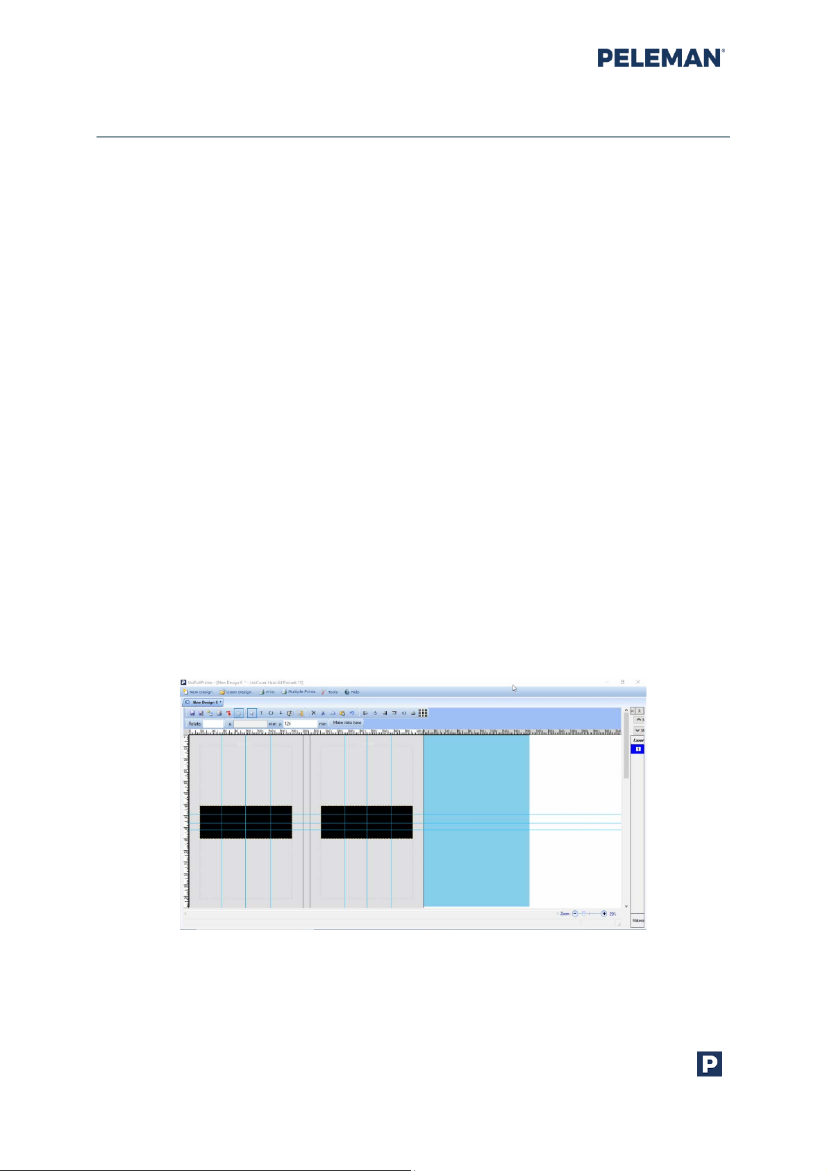
Click on Design Print button to open the new design based on the selected template and
associated object orientation. A screen similar to figure 17 will appear on the screen.
Figure 17: Design Window Based on Selected Template and Object Placement
With the help of available tools provided in the toolbar, create the desired text and graphics
to be printed on the cover. Section 5.5.6 of this document may be referred to for more
information on the toolbars.
5.5.1 Object Orientation
Important notes about object orientation:
• Due to the printhead width, each section of the design box is 57 mm high
• Printing is done from left to right in segments of 57 mm
• All design elements must fit within the margins of the print areas. You can enlarge
print areas to over 57mm. In this case, when image or text does not fit within one
area between the dashed lines, the element will be split and made with 2 or more
strokes. In some printers, it can result in incomplete or imperfect areas.
• Orientation must be considered according to the elements used in these fields
Read more about print areas in section 5.5.4.
Peleman Industries

Flat Bed Foil Printer User Guide
30
5.5.2 Printing on Spine
Printing on spine is only possible when the spine is horizontally oriented. Figure 18
illustrates the placement of print areas according to the orientation of the cover.
Figure 18: Vertical Spine Orientation (Left) and Horizontal Spine Orientation (Right)
Important notes about printing on spine:
• Select horizontal orientation of the spine for printing on spine.
• First, do a test print on the spine to double-check correct location.
• After a power cycle, the machine will auto calibrate on a bit different direction.
Recheck the spine location first before printing on actual cover.
• When set up correctly, the centre of the head will go down in the centre of the
spine.
• Elements inside a print area can be rotated at any degree but the direction of the
print areas is set when object orientation is selected.
• Vertical spine orientation is most likely to be selected when designing the front and
back of a cover, not the spine itself.
• The orientation of the design is saved during template selection. If the selected
design for cover requires more than one orientation, two individual designs are
needed on the same kind of template.
Peleman Industries

Flat Bed Foil Printer User Guide
31
5.5.3 Parts of Printing Object
Cover with Spine
A cover with a spine should always lay flat on the printer’s main table as seen in figure 19.
The printer will print on the side facing upwards. A cover usually encompasses three
printable parts, i.e. the front side, the back side and the spine.
Figure 19: Vertical Spine Orientation (Left) and Horizontal Spine Orientation (Right)
Exceptions
• If the cover is placed on the table in a vertical spine orientation, the spine is
unprintable.
• When a cover part is placed outside the printer table, the part is unprintable,
e.g. the back side in horizontal spine orientation shown in figure 19 is partially
outside the printer table, so it is not printable in this orientation.
5.5.4 Print Areas
Print areas are non-printable black or white windows that are used to add printable
elements in a design. By default, a print area is placed on every editable side of an object
when a new design is opened. These areas are 57mm wide due to the size of the print head.
Users can enlarge these areas. In that case, the printer will print the design in more than
one stroke. Users may add or remove print areas according their design requirements. To
add a new print area, click on the associated toolbar button for adding print area. The
associated toolbar button is described in toolbar group 1 of section 5.5.6.
Print areas can also be moved up and down to a desired location by clicking on the given
print area and dragging it (drag and hold) with the mouse as well as by using arrow keys on
keyboard. Print areas can be aligned to the top, middle or the bottom of the object by
clicking on the given element alignment buttons in the design toolbar described in toolbar
group 5 in section 5.5.6.
Peleman Industries

Flat Bed Foil Printer User Guide
32
Images can be imported to the print areas, and text can be typed inside these by using the
associated design toolbars described in toolbar group 1 and 2, respectively, of section 5.5.6.
Inserted elements can be moved around by using the same options as when altering print
areas. Only parts of the element placed inside the print area will be displayed and printed.
PRO Tip: Repeat the same design by selecting the print area (with your
design placed in it) and copy-pasting it on same spot (Ctrl+C – Ctrl+V).
The machine can print the selected design repeatedly up to 10 times on
the same spot.
It is recommended to have thick foil layer on the same object or
to make multiple prints on different objects.
5.5.5 Print Margins
In order to ensure the quality of the print, a certain size of margins always remains
unprintable. Thus, it is not possible to print edge to edge on any objects. These margins are
defined by the Flat Bed Foil Printer PC Tool and are unchangeable.
Standard margins are 19mm and we advise these margins to prevent errors/incorrect head
placement. Narrow margins are 8mm and available during custom template creation.
Section 10.5.1 may be referred to see the values of these margins.
Flat Bed Foil Printer PC Tool will automatically reject elements to be placed on these print
margins.
Figure 20: Margins (grey zone around the template)
Peleman Industries

Flat Bed Foil Printer User Guide
33
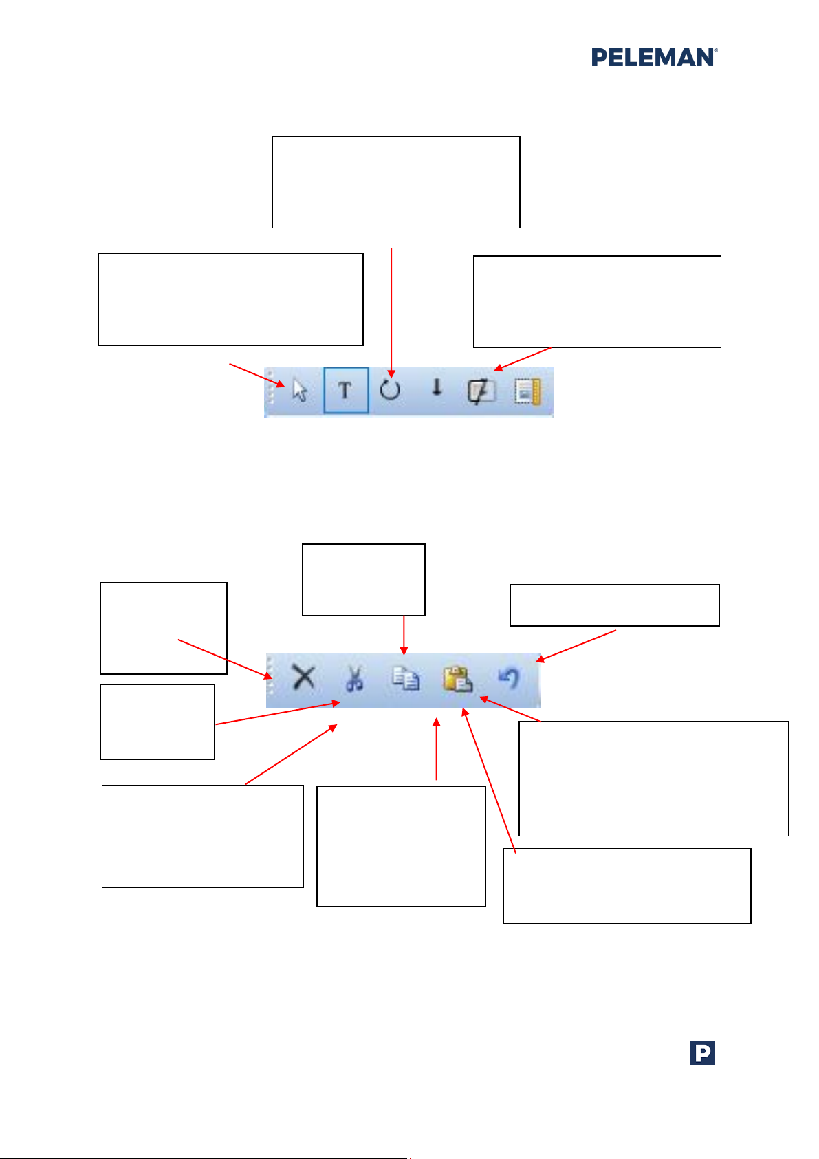
Save Design: Save
changes / modifications
for the design
Add Print Area: Add a new
print area to the selected
location (print area = zone
with objects to print)
Import PDF: Import PDF
page from the file system
to add it to the design as
an image object
Save As Design: Save the
changed / modified design
under a new name
Import Image: Import
images from file system
to the design
Show / Hide Layer Window:
Show or hide layer window.
By default, the layer
window is shown
5.5.6 Design Toolbar
The design toolbar, shown in figure 21, can be seen at the top of the design tab subwindow. It offers various functionalities for different purposes. The toolbar groups can be
reorganised and relocated into different lines to suit the user’s needs.
Figure 21: Design Toolbar
The following is a brief description of the toolbar options:
Group 1: Functions
Peleman Industries
Figure 22: Design Toolbar Group 1 - Functions
Flat Bed Foil Printer User Guide
34
Select Tool: Enable selection and
movement of design elements and
print areas. See section 5.5.9 for
more information
Text Tool: Create text
boxes and edit text inside
print areas. See section
5.5.8 for more information
Rotate Tool: Rotate a selected
element. Drag the element to
rotate it. See section 5.5.10 for
more information
Vertical Text: Change
horizontal text line to
a vertical text line
without changing
text direction / angle
Show / Hide Variable:
Show / hide the variable marking
checkbox used with the text
boxes
Show / Hide Background: Show /
hide the background colour of
the selected cover
Delete:
Delete
selected
elements
Cut:
Cut selected
elements
Copy:
Copy selected
elements
Paste: Insert cut or copied elements.
Elements will be inserted in the
centre of the selected print area.
Press the Shift key while inserting, to
move the elements in place
Undo: Undo recent actions
Group 2: Tools
Figure 23: Design Toolbar Group 2 - Tools
Group 3: Edit Functions
Figure 24: Design Toolbar Group 3 – Edit Functions
Peleman Industries

Flat Bed Foil Printer User Guide
35
Font Family: Available
font types that can be
used in text boxes. Font
of the selected text boxes
will change according to
the user’s preferred font
Bold: Make the
text of selected
text boxes bold
Font Size: Select the size
of the font to be used for
different text elements.
User may also enter the
preferred size (up to 900)
Italic: Make the
text of selected
text boxes italic
Underline:
Underline the
text of selected
text boxes
Align Left: Align the
selected or current text
line of the selected text
box to the left-hand
side
Align Centre: Align
the selected or
current text line of
the selected textbox
to the centre
Align Right: Align
the selected or
current text of the
selected text box to
the right hand side
Group 4: Text Editing
Text Editing toolbar will only be shown when a text box is selected and text in it is being
inserted or edited. The given font options will apply to the selected text in the text box or to
the current cursor position if no text is selected. Similarly, the alignment options will apply
to the selected lines within a text box or to the current line, if no text is selected.
Peleman Industries
Figure 25: Design Toolbar Group 4 - Text Editing

Flat Bed Foil Printer User Guide
36
Align Left: Align the
left side of the
selected elements to
the same location
Align Centre: Align
the centres of
selected elements to
the same location
Align Right: Align the
right side of the selected
elements to the same
location
Align Top: Align the
top side of selected
elements to the same
location
Align Middle: Align the
middles of the selected
elements to the same
location
Align Bottom: Align
the bottom side of
selected elements to
the same location
Align in Centre of Closed Cover:
Align the centre of selected
elements to the centre of the
closed cover. The selected text
is also centered within the box
Rotate: Rotate the selected
elements to the required angle.
By default, the angle of rotation
for an element is 0 degree
Group 5: Element Alignment
Figure 26: Design Toolbar Group 5 - Element Alignment
If a single element is selected, the alignment buttons will align to the edges and centre of
the print area.
Group 6: Rotation Degree
Figure 27: Design Toolbar Group 6 - Rotation Degree
Peleman Industries

Flat Bed Foil Printer User Guide
37
X Coordinate: Indicates the X
location of the selected element
or print area
Y Coordinate: Indicates the Y
location of the selected element
or print area
Units of XY Coordinates: May be
either mm or inch based on the
selected setting in ‘Tools’
Make Database: Creates a TXT or
CSV database in a new tab. This
database contains values for the
selected variable text boxes in
the associated design.
To make the text variable, right
click on the text box and select
the option.
Group 7: XY Coordinates
Figure 28: Design Toolbar Group 7 – XY Coordinates
Group 8: Make Database
Peleman Industries
Figure 29: Design Toolbar Group 8 – Make Database
Flat Bed Foil Printer User Guide
38
5.5.7 Saving Design
To save a new design, press the Save button in the design toolbar. A dialog box will appear
to enter the name of a file. The Flat Bed Foil Printer design files will have the file extension
.upf. The default path for saving any design is a subfolder named Flat Bed Foil Printer
Designs located in the My Documents folder. It is recommended to save all Flat Bed Foil
Printer designs in either the default folder or within one of its subfolders.
To save the changes done to an existing design, press the Save button in the design
toolbar, and the changes saved to the existing design will be saved under the same file
name.
To save an existing design under a different file name, either click on the Save As button or
hold down Ctrl +Shift keys of the keyboard and then select Save. A dialogue box will open
to enable entry of another file name.
Toolbar group 1 in section 5.5.6 may be referred to for more information about Save and
Save As toolbar buttons.
5.5.8 Inserting Text and Images
Text and images can be inserted in the displayed print areas. They will appear inside the
dotted-line boxes with handles in every corner. The handles are displayed as hollow
squares. Text boxes and image boxes are in general referred to as design elements in this
document. Figure 30 and figure 32 are examples of how images and text boxes appear.
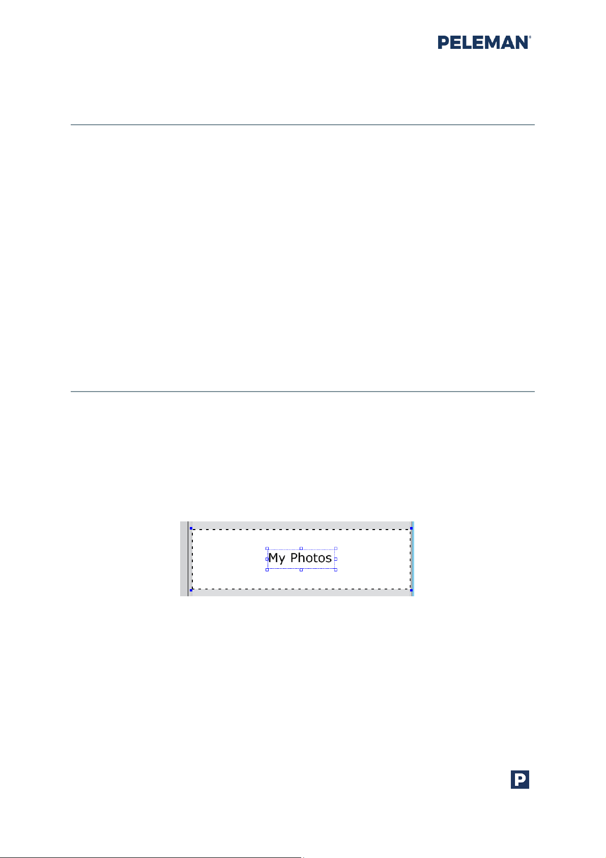
To insert text, the given Text tool button in the design toolbar is used. When the Text tool is
selected, click on a desired spot inside a print area. When the text box appears, enter the
text while the Text tool is selected. Place the cursor in the required location to edit the text.
Figure 30: Text box placed in a print area containing the text “My Photos”.
To resize the text box, click on the Select tool in the design toolbar. When mouse is over the
handles, the select tool turns into a Resize tool. Click on the corner and drag the mouse
while holding down the mouse button.
When the Text Auto Resize option is on, the text box will be automatically resized according
to the text size. Section 5.8.1 may be referred to for further information.
Peleman Industries

Flat Bed Foil Printer User Guide
39
Tip: Double-click on a text box with Select tool and the tool will change
into Text tool, enabling text editing.
Single clicking with the mouse at any text position will place the cursor at click location and
make the text editable. On the other hand, double-clicking with the mouse button will
select the entire text within the text box. Associated keyboard shortcuts may be used for
cursor movement and text selection. Section 10.1 of this guide may be referred to for
available keyboard shortcuts for different functionalities.
To insert images, they must be first imported using the Import Image button in the design
toolbar. Select the preferred print area for the image before proceeding with the Import
Image option. Upon pressing the Import Image button, a dialog box will appear enabling
search for image files. Please note that only the following image file types are supported by
the Flat Bed Foil Printer PC Tool: BMP, GIF, JPG, TIFF and PNG. Select the desired image file
and click the Open button of the file selection dialog box.
Tip: PDF pages may also be imported as images using Import PDF
toolbar button discussed in toolbar group 1 of section 5.5.6.
Whether the selected image is grayscale or colourful, an image threshold menu will
appear, like the one shown in figure 31,, with the following options.
Figure 31: Image Thresholding Menu
• Invert Colour: The negative of the image (black=to be printed)
• Colour Conversion: Offers a choice between Dithering and Threshold
• Cropping: Makes it possible to use selected part of the image.
Peleman Industries

Flat Bed Foil Printer User Guide
40
When Dithering is selected, the image is
formed by a cluster of closely placed dots,
creating an illusion of contrast
When Threshold is selected, the image is
black and white, without any contrast. The
threshold can be adjusted using the plus
and minus buttons. Once the threshold level
is satisfying, press the Insert button
PRO Tip: In some colour
images, you can split the
colours with the threshold
function. By importing the
parts in different layers,
you can make multi-
coloured foil images in
minutes.
The image will appear in the selected print area as shown in figure 32. Use the arrow keys
on the keyboard or the mouse to drag and move the image to the desired location.
Figure 32: Image of palm tree placed inside print area
Peleman Industries

Flat Bed Foil Printer User Guide
41
Tip: Drag down the dotted line to open the print area for images larger
than 57 mm.
5.5.9 Selection, Movement and Alignment of Elements
An element may be selected by clicking on the Select tool shown as an arrow in figure 23
and then clicking on the element. To select multiple elements, hold down the Shift key on
the keyboard and then click on the elements one by one.
An element may be moved by selecting it with the mouse and then dragging it to the
desired location, while holding down the mouse button. A borderline helps to avoid the
element to be placed completely outside the print areas. This limit is 50% of the element to
be placed outside the print area. When moving an element outside the print area, only the
part inside the print area remains visible and will be printed. Elements can also be moved
using arrow keys on the keyboard.
An element may be aligned to the top, middle or bottom side vertically and to the left,
centre or right side horizontally within its design area by selecting the element and then
clicking on the appropriate element alignment button shown in figure 26. Similarly, an
element may be dragged to a specific location by clicking on the element with the mouse
after selection, and then dragging it to the required position within its design area while
holding down the mouse button. Section 5.5.12 of this document may be referred to for
more information about aligning elements with guidelines.
When multiple elements are selected and aligned using the toolbar shown in figure 26, all
elements will get aligned according to the first selected element. For example, if multiple
elements need to be aligned to the left, then all elements will move except the first
selected element, in such a way that the left side of all elements will be aligned to the left
side of the first selected element.
Peleman Industries

Flat Bed Foil Printer User Guide
42
Tip: For optimal results, elements must be placed between the dotted
lines. Elements touching these dotted lines will lead to broken designs
and imperfect results.
5.5.10 Rotation of Elements
A user may rotate any element either manually through the Rotate button shown in figure
23, or automatically, to the desired angle by entering the value of required degrees of
rotation for the element in the rotate field shown in figure 27.
To rotate an element manually, the user must select the element and the Rotate button
from the toolbar shown in figure 23. After that, drag the mouse while holding down the
mouse button until the element is rotated to the required degree.
The rotate field in toolbar shown in figure 27 will also show the value of the rotation angle
for the selected element. A user may also rotate the element to the desired angle by
selecting the element and then entering the value of degrees in the rotation field.
Tip: While the Shift key on the keyboard is pressed, the Rotate tool
temporarily functions as the Select tool
Please note that when selecting multiple elements, each element will rotate about its own
centre. Section 5.5.9 of this document may be referred to for more information.
5.5.11 Foil Colour Layers
The Flat Bed Foil Printer supports all foil colours discussed in section 4.1. Each colour is
handled as a separate layer. These layers are shown in a separate layer sub-window that is
visible on the right side of the design tab. If the layer window is not visible, click on the show
/ hide layer window toolbar button. By default, the layer window automatically resizes in
width to hide most of the contents. By placing the mouse over this layer window, the
window can be expanded. Users may use the pin button at the top of this layer window to
enable / disable this auto hide feature of the layer window.
By default, the selected foil colour is A-Metallic Gold. If another foil colour is to be used for
printing, it can be selected in the layer window. Changing the foil colour of the selected
layer changes the print colour for each element associated with that layer. The foil colour
per group (A, B, C, D or E) is only a preview and will not result on settings for the selected
material. Please note that not all groups contain same colours.
The cover material associated with the selected layer is displayed at the bottom of the layer
window. By default, ‘Black’ material is selected. Users may select the material from the
given list associated with each selected layer. The material will result on the print settings.
Change settings for that specific material in the selected foil group if print quality is not as
expected.
Peleman Industries

Flat Bed Foil Printer User Guide
43
Figure 33: Layer Window
Multiple colours may be used on one object. Add separate layers in layer window for each
colour. Elements inserted in one foil colour layer stay visible when another foil colour layer is
selected. Only foil colour layers that contain elements will be printed. The Flat Bed Foil
Printer PC Tool software will guide the user through the process of changing foils.
Users may activate or deactivate the visibility and print function for each layer by choosing
the appropriate checkboxes for each layer. New layers can be added; existing layers can be
deleted as well as rearranged within the layer window by using the associated buttons
available at the top of the layer window.
Tip: The material will define the ideal settings. To change settings due to
unsatisfactory print results, either click ‘Adjust Print Settings’ in the top
menu or go to ‘Tools’ -> ‘Customize’ and edit settings of existing material
or add a new one with other settings. Users will need to select the
corresponding material in material window before printing on it.
Peleman Industries
Flat Bed Foil Printer User Guide
44
5.5.12 Rulers & Guidelines
The rulers are usually used to align elements in the design window. Two types of rulers can
be seen during the design process, i.e. horizontal ruler and vertical ruler. The horizontal
ruler is displayed at the top of the design and is used to align elements horizontally. On the
other hand, a vertical ruler is displayed on the left side of the design and is used to align
elements vertically. The white area of the ruler corresponds to the allowable area where
elements may be placed, while the inactive grey areas indicate those parts of the object
where a user cannot insert any design element. The inactive grey area is either caused by
print margins or because a part of the object is not supported by the printer table. Section
5.5.3 and section 5.5.5 may be referred to for more information.
By default, the rulers are always displayed during the design stage. Users may show / hide
rulers using the settings tab in the available tools. The default unit for displaying
measurements on the rulers is millimetre (mm). Users may change the units to display
measurements on the rulers from the Settings tab in the available tools. Section 5.8.1 of this
document may be referred to for more information on how to show / hide rulers and how
to change units.
Guidelines for alignment are non-printable light blue colour lines, as shown in figure 34,
that may be used to align elements, corresponding to some specific measurements on the
ruler. To place a horizontal guideline, the user will have to click on the top ruler and drag
the pointer line on the design area to the required corresponding position of the vertical
ruler while holding down the mouse button. Similarly, to place a vertical line, the user will
have to click on the left ruler, and drag the pointer line on the design area to the required
corresponding position of the top ruler, while holding down the mouse button.
Users may add any number of such guidelines to a design. Similarly, to move any guideline
to another location, a user may click and drag it to elsewhere, by holding down the mouse
button during dragging.
Figure 34: Rulers and Guidelines for Alignment
Peleman Industries

Flat Bed Foil Printer User Guide
45
5.5.13 Multiple jobs
When printing multiple books with different text, it is suggested to use the multiple jobs +
variable functions.
• Step 1: Create a text box and enter your text (example “name”). This text will
be changed by your custom text in data file later. Please make sure the text
box is big enough to prevent incomplete or spilt text. We advise to make the
text box from side to side and align text in centre, if needed.
• Step 2: Make the text box variable by selecting Variable Text tool from the
toolbar or right clicking with the mouse on the text box, then selecting the
variable checkbox appearing above the textbox and marking it for multiple
values.
• Step 3: Save the design and then click on Make Database button in the
toolbar to create the TXT or CSV database file. The database will appear in a
new tab next to design window tab.
• Step 4: You can edit the database file in the PC Tool software (go to step 5) or
another programme like Notepad or Excel. The database file will have the
same name as the design but with a different extension (can be found in the
same folder where your designs are saved). You can now edit the separate
file externally and save it under the same name and extension.
• Step 5: Use multiple lines. Use a new line for each word. Or, if values are
entered externally and saved in another program (see step 4), you may
refresh the database to make sure everything is set correctly.
Example:
Name 1
Name 2
Name 3
….
• Step 6: Go back to your design. Click on Multiple Prints at the top of
application. Select Print variable design with option all variables or select
specific variables like described in the window. Finally, click on Print button
in the dialog box to start printing.
Peleman Industries

Flat Bed Foil Printer User Guide
46
• Step 7: The print process will start. Follow the instructions on the screen and
replace the cover after each print.
5.5.14 Design Zooming
Users may zoom IN or zoom OUT within the design window using either the slider or the
associated plus and minus buttons provided at the bottom right side of the application as
shown in figure 35. Alternatively, the Shift + mouse scroll can be used to zoom IN or OUT.
Figure 35: Zoom Slider & Buttons
5.6 Open Design
To reopen a design, click on the Open option. The menu items are provided at the top of
the application window. A dialog box will appear to select the design file. Flat Bed Foil
Printer design files will have the file extension .upf.
5.7 Print Design
To print any saved design, the design must be opened in the application. To print the
design, click on the Print button in the menu at the top of the application window.
Similarly, a new design can also be printed right after the completed process by clicking on
the Print button without closing the design.
Follow the instructions carefully to achieve perfect printing results.
Peleman Industries

Flat Bed Foil Printer User Guide
47
To print multiple copies of the same design, use the Multiple Prints button instead of using
Print button. Similarly, to have different prints for the same design by replacing multiple
values for the text in text boxes, use variable design option of multiple prints. Section 5.5.13
of this manual may be referred to for more information.
5.8 Tools
Other multiple tools are available in Flat Bed Foil Printer PC Tool. These additional tools are
related to different settings, updates, service request, calibrating the Flat Bed Foil Printer,
creating and managing templates and more. A brief overview of these additional tools is
provided here for reference.
5.8.1 Settings
The settings tab in tools shown in figure 36 details the customisation of the application.
Figure 36: Application Settings Tab in Available Tools
• Changing Units
This setting relates to the units used on the ruler when it is displayed during the
creation / editing of designs. Its default value is millimetre (mm).
Peleman Industries
Figure 37: Units Setting for Rulers in Tools

Flat Bed Foil Printer User Guide
48
• Switching Display of Ruler On / Off
Enabling or disabling the ruler. Users may set it to on state if the ruler is required
to be displayed; otherwise it is set to off state. Its default value is on.
Figure 38: Ruler Display Setting in Tools
• Snapping On / Off
Enabling or disabling the functionality of snapping of objects against the
construction lines. Its default value is on.
Figure 39: Snap Setting in Tools
• Automatic Search for Updates
Enabling or disabling automatic search for updates. Its default value is on.
Figure 40: Setting in Tools for Automatic Search for Updates
• Enable All Messages
Enable all Flat Bed Foil Printer messages. Messages can disabled by choosing
the “Don’t display this message again” option. By default, all messages are
enabled.
Figure 41: Setting in Tools to Enable All Flat Bed Foil Printer Messages
• Printing Parameters
Customisation of parameters associated with printing. It is one of the most
essential functions in the software as it allows users to adjust settings for the
different foil materials.
Figure 42: Setting in Tools to Customise Printing Parameters
The dialog box, like the one shown in figure 43, is displayed when clicking the Customize
button. This dialog box contains settings for different printing parameters for each type of
Peleman Industries

Flat Bed Foil Printer User Guide
49
supported foil. The parameters include torque, burn time and printing speed for both sides
of the cover as well as for spine.
• Torque value is between 0 and 240. Increasing the torque value will result in
more pressure on the printing material. If the torque is too high, the printing
material can be damaged leaving indentations. If it is too low, it can cause an
incomplete print.
• Burn time value must be from 300 to 2500. The foil needs heat to stick to a
material. The higher the burn time the more heat is being transferred to the foil.
If the heat is too high, the foil will break and loose shine. If it is too low, it will
result in an incomplete print.
This setting is to be adjusted when the torque setting is maximal for your
material without leaving indentations.
• Printing speed must be from 5 to 25. The value of printing speed is converted to
actual speed in such a way that for example a value of 25 will mean a speed of 25
mm / second.
It is recommended to keep the speed around 10 and adjust other settings first.
You can adjust printing speed when burn time is maximal but there is still not
enough ‘heat’ to allow the foil transfer onto the material. Increasing print speed
will also increase burn time.
• Motor speed adjusts the speed for winding up the foil. The higher the speed the
higher the tension.
This setting needs to be adjusted when the foil starts wrinkling under the
printhead for custom materials. Usually a combination of 10 for print speed and
30 for motor speed is recommended.
The recommended default values for these settings depend on the type of cover material.
Section 10.3 may be referred to for further details in this regard.
Peleman Industries
Figure 43: Settings for Printing Parameters

Flat Bed Foil Printer User Guide
50
• Transportation
This setting is used to move the head to preset position, suitable for transporting
the Flat Bed Foil Printer to a different location. This position is also frequently
used for servicing the machine. This preset position is the so-called safe location,
with the locking tool must be mount for transportation.
Figure 44: Setting in Tools for Transportation
• Smart Temperature Control
When Smart Temp Control (SMT) is “On”, then automatic temperature
adjustment in printhead is used during printing. By default, this setting is off.
The setting is not shown if the connected hardware does not support this
feature (below version 2.17).
The smart temp control can improve temperature spreading in the printhead
making it possible to print large and complex images without burning the foil.
Figure 45: Settings in Tools for Smart Temperature Control
• Printhead Calibration
Printhead calibration when switched on uses the device specific R-value for
calculation of desired burntime to be used for better quality printouts. By
default, this setting is off. The setting is not shown if the connected hardware
does not support this feature (below version 2.35).
Please note that printhead must be calibrated first. Via Testing and Calibration
section it is possible to calibrate the printhead.
Figure 46: Settings in Tools for Printhead Calibration
5.8.2 PELEMAN Products
This option opens the PELEMAN website in the system default browser. The designated
website displays useful information about all PELEMAN products. For further information
or to place an order, please contact your local distributor.
Peleman Industries

Flat Bed Foil Printer User Guide
51
5.8.3 Check for Updates
Cheching the availability of new software and firmware updates from the designated
server. It may also be used to update firmware or software by downloading the updates
from the server.
The associated printing device must be connected to the system before checking for
updates or updating firmware. The system must also be connected to the designated
server through Internet / network connection to check and download updates from the
server.
Figure 47: Tools to Check for Updates
If the associated printing device is not connected while checking for updates, then a
warning message will prompt the user to connect the printer to the system, as shown in
figure 48.
Figure 48: Warning Message if Printer is Not Connected
Similarly, if the system is offline, i.e. not connected to the server, then another warning
message will appear asking the user to connect to the server, as shown in figure 49. Please
try to check for updates later.
Peleman Industries

Flat Bed Foil Printer User Guide
52
Figure 49: Warning Message if Not Connected to Server
The Search button connects the application to the designated server to check the
availability of new software and firmware updates. The progress bar displays the
completion percentage of the request. The same progress bar is also displayed while
updating the firmware / software.
Users may click on Update printer firmware to get the updated firmware from the server
and install it on the Flat Bed Foil Printer. This button only becomes enabled when a new
firmware update is found on the server.
Similarly, users may also click on Update Flat Bed Foil Printer PC Tool to update the current
version of the Flat Bed Foil Printer software application. This button is only enabled when a
new software update is found on the server.
If available, current and new firmware and software versions, will be displayed next to the
respective buttons used to update these.
Please note that it is possible to receive error messages of unsuccessful installation of
firmware while it is installed correctly in software versions 1.0.0.63 and 1.0.2.0.
5.8.4 Request for Service
Please contact our local representative and provide all necessary information, including
serial number (can be found on the back) as well as images or a video of the issue. You may
also include a picture of the testing page and log files (via help/? button).
5.8.5 Manage Templates
User-created templates may be managed by the user through Manage Templates tab in
the tools shown in figure 50. User Templates button can be used to see all user created
templates. All button must be clicked to see all available template. There are two options to
manage user templates: a template can be deleted or edited by clicking on or
respectively on the corresponding template. These two options are disabled for system
templates.
Peleman Industries

Flat Bed Foil Printer User Guide
53
New templates may be created by the user by selecting the Create New Template option.
Section 5.8.5.1 may be referred to for further information about the creation of new
templates. Similarly, the templates may be imported or exported. Section 5.8.5.2 may be
referred to for available options regarding importing and exporting templates.
Figure 50: Screen for Managing Templates
5.8.5.1 Create New Template
Users can create new templates based on custom dimensions. Most common PELEMAN
products are included in the Flat Bed Foil Printer PC Tool by their product names as
templates. If a PELEMAN product cannot be found, please check for updates or create a
new template. Go to section 5.8.3 to read more about updating the Flat Bed Foil Printer PC
Tool.
New templates must be based on a printable object. The measurements to be taken are
described in this section.
When Create new template tab is selected, a warning message will appear, as shown in
figure 51, reminding the user of the severity of incorrect values.
Figure 51: Warning Message at Start of Creating New Template
Only click the Continue button if you are sure about the values you are about to type in.
Failure to do so can cause severe damage to the machine.
The maximum dimensions of the template are 430x304 mm. The actual object, however,
can be larger. However, the actual printed area cannot be larger than 440x280 mm.
Select the type of cover for the new template and then click on Next.
Peleman Industries

Flat Bed Foil Printer User Guide
54
Figure 52: Screen for Selecting Type of New Template
Now, insert dimensions for the new template in appropriate fields shown in figure 53. The
values of the dimensions refer to the height, width, thickness etc. of the object to be used
with the new template. Dimensions are by default entered in mm or inches according to
the selection in settings described in section 5.8.1.
Enter the exact dimensions of the print object. If the entered dimensions are not supported
by the Flat Bed Foil Printer, warning messages will appear. If the dimensions are correct,
the desired template might not be supported by the Flat Bed Foil Printer, either because
the dimensions are too large or too small. Appendix section 10.2 may be referred to for
further information regarding supported template dimensions.
If a typing error caused the warning message, the value can be corrected. After inputting all
values, click on the Next button to continue.
Figure 53: Screen for Inserting Dimensions of New Template
Peleman Industries

Flat Bed Foil Printer User Guide
55
When creating a template type 1b, an additional screen to get measurements related to
the window on the cover will appear.
Figure 54: Screen for Inserting Dimensions of Window in New Template
In the next screen shown in figure 55, the user will be required to select a unique name for
the new template. Please note that the names of Flat Bed Foil Printer existing templates
cannot be used for new templates. Click on Save button to create a new template.
Figure 55: Screen for Selecting Material, Softness and Name of New Template
After the successful creation of a new template, a message will appear asking the user to
create a new design based on this newly saved template. The user may then continue.
5.8.5.2 Importing/ Exporting templates
With Import / Export buttons, it is possible to exchange templates. Use Export button to
save the selected template as a .upt file. Use Import to load a template from a .upt file. To
export all user templates, Export All button may be used.
Peleman Industries

Flat Bed Foil Printer User Guide
56
5.8.6 Testing and Calibration
5.8.6.1 Calibrate Printhead
Due to production tolerances, the R-value between different printheads can vary from the
“ideal” value of 3000.
The different R-values between printheads result in different print results as the value
directly influences the amount of heat generated by the printhead.
Different print results can be avoided by providing the R-value of the specific printhead in
the software. The R-value (4 digits) can be found on the printhead as indicated in the
picture below.
Once the R-value is provided in the software AND the “printhead calibration” function is
activated, the software will adjust the R-value deviation according to the ideal value of 3000
and generate print results that are consistent between different printers.
This function together, with Smart Temp Control, ensure better print result with standard
settings.
Figure 56: Calibrate Printhead tab
To switch ON: Settings-> Printhead Calibration (ON)
Enter the R-vale written on the label of the printhead (field with 2500) and hit ‘Calibrate’,
confirm and double check with ‘Refresh R-value’ button.
Make sure to change this value after replacing main board or printhead.
Peleman Industries

Flat Bed Foil Printer User Guide
57
5.8.6.2 Quality testing
In quality testing tab you can find a testing page with different figures and lines. This page
will help you in calibration, alignment and quality testing, when needed.
Just make sure the substrate/material is well fastened, select correct foil and material and
hit ‘Print testing Page’ button.
You can use quality testing page design to send to support or show to your technician.
5.8.6.3 Position calibration
Calibration is a process during which the hardware prepares itself and corrects its internal
processing errors related to positioning its printer head for accurate printing on covers.
Follow the instructions to perform calibration and its associated testing.
The calibration is not used to solve misalignment issues and the position is up to 3 mm
accurate (compared to the design on the screen) for machines with serial number below
PU063xxxxx.
To perform calibration correctly, first print the circle and measure the distance to the edges
with high precision. Software will tell you if calibration is needed or not. If calibration is not
needed, please exit the process.
If calibration is needed, hit the ‘calibrate’ button and follow the instructions displayed on
the screen. Make sure you are measuring the upper left corner of the printed dot during
the calibration. Measurement must be very precise.
Reprint and measure the circle to make sure calibration is successful. Restart the software
and repower the machine before making a final test of the circle. If the circle is shifted after
power cycle you may need to update your firmware version and calibrate there.
Please note that it is required to use a basic Peleman cover or sheet of
Peleman Industries
Figure 57: Calibration Start Screen
paper with the minimum dimensions of 150x150 mm and place it
properly in the corner as shown in the image.

Flat Bed Foil Printer User Guide
58
5.8.6.4 Torque sensor test
Figure 58: Torque Sensor Test
To test the pressure sensor, use the ‘Torque Sensor Test’ tab. It can be used when the head
error is displayed on the screen or when you have issues in downwards movement.
Follow the instructions on the screen carefully. If the values given in the instructions are
different from your software, please proceed to the troubleshooting section or contact our
distributor/our official technician. It is not advised to use this functionality without special
training and knowledge. However, your distributor or technician may ask you to preform a
test before considering a replacement or intervention.
Basic test:
1. Klick on ‘read torque sensor’ button after the foil is removed.
2. ‘Torque Value’ Must be below 20. Usually it is around 5. If it is more as 20 – it means
that the pressure sensor is reading pressure in rest. It can be due to the stuck
mechanism or damaged loadcell. To lose the mechanism push the printhead up
manually a few times. If the value does not return to normal it is advised to contact
our specialist to grease the mechanism or replace the loadcell.
3. Second test is on maximum pressure value. When pressing the head up manually
till the mechanical stop – it must show a value of 248. A bit more is possible but not
less as 241. If the value is way below 248 it is advised to double check the firmware
Peleman Industries

Flat Bed Foil Printer User Guide
59
version (for latest version) and/or replace the loadcell. Doublecheck the connector
first before contacting our specialist and describe to them your troubleshooting
steps.
The ‘Move to Reading Position’ button and ‘Set Torque’ functionalities are reserved for
further troubleshooting by technicians. They will need a weight scale (capable to at least
read 20kg). For a set torque of 240 the weigh is 11-14kg. When it is below 11kg – replacement
of the compression spring and/or compression pin can be considered.
5.8.6.5 Update firmware
Firmware update functionality (outside the live server) is reserved for technicians with
training. Password will be provided only to them. Therefore, please check for updates via
live server first by using ‘check for updates’ functionality.
5.8.6.6 Position and Motor Test
This functionality is also reserved only for the technicians. You may check the X or Y home
position sensors functionality during troubleshooting. Or move the machine to a specific
location for motor testing.
The foil motor can be also tested using this tab.
5.8.6.7 Move to extremes
This functionality is used for motor spindles testing. After replacement or grease of the
spindles it is advised to run the printer back and forth a few times.
5.8.6.8 Step Size
The step size functionality can be used only by technicians after motor replacement in old
printers with serial number lower as PU024xxxxx. In these machines old motors must be
replaced for new since it is not more possible to order old motor type. Therefore, step size
must be changed manually for this specific motor, usually from 5000 to 3969.
Also, it is possible that after firmware update the step size of old machine will be replaced
for new and you’ll note distortion in print result (printer will also go slower or faster). In this
case you may also need to overwrite the step size with correct value.
Since this functionality can damage the machine if used by unexperienced user – it is
password protected and available only to the trained technicians.
Peleman Industries

Flat Bed Foil Printer User Guide
60
5.8.7 Service Menu
The Service Menu is used to check the auto status and printer statistics. ‘Refresh’ button
can be used to display the data.
Auto status consists of fields relating to the Flat Bed Foil Printer firmware and is very useful
to a technician to check all errors. Please make a screenshot and send it together with your
issue description when asking for support.
Printer statistics display the performance and counters related to different hardware
activities. Printed length and printing sessions may be a very interesting indicator for
maintenance or counting the amount of work that was done for a specific period.
Figure 59: Service Menu in Tools
5.8.8 About the Foil Printer
This option in the tools is used to check the version numbers of the software application as
well as firmware. This screen also displays the unique ID of the connected Flat Bed Foil
Printer hardware. It is advised to inform us about the s.w. and f.w. versions when contacting
for support, reporting bugs or suggesting an improvement.
Figure 60: About Flat Bed Foil Printer
Peleman Industries

Flat Bed Foil Printer User Guide
61
5.8.9 Help Button
The help option opens a tab containing help information related to the software.
Figure 61: Built-In Software Help
In newer software versions three options are displayed:
• User Guide: by clicking on this option the user guide related to this software
version will be displayed. This is the first help manual that you’ll need in case
of questions. User guide contains basic information about the printer and
software. For more information, please contact our distributer in your
country.
• Logs: logs are automatically saved software commands between user,
software and firmware. You’ll need it in case of software bugs so our
developers can analyse the issue. Copy and send it in a text document when
requesting for service.
• What’s New: This option will open the pop-up window about what’s new in
this version of the software.
Peleman Industries

Flat Bed Foil Printer User Guide
62
5.9 Uninstall
Flat Bed Foil Printer PC Tool can be uninstalled by using one of the below options.
5.9.1 Uninstallation Using Start Menu
To uninstall the software application, go to All Programs in the Start Menu followed by Flat
Bed Foil Printer PC Tool subfolder and select the option Uninstall Flat bed Foil Printer PC
Tool as shown in figure 62. Follow the instruction on the screen to complete the
uninstallation process.
Figure 62: Uninstall Option in Start Menu
5.9.2 Uninstallation Using Control Panel
To uninstall the software application, go to Programs and Features within the control panel
to see the list of installed programmes. Select Flat Bed Foil Printer PC Tool from the list of
installed programs as shown in figure 63. Then either select Uninstall from the menu
options displayed above the list of programs or right click on Flat Bed Foil Printer PC Tool &
then select Uninstall from the menu to uninstall the software application. Follow the
instruction on the screen to complete the process.
Peleman Industries

Flat Bed Foil Printer User Guide
63
Figure 63: Uninstall Options in Control Panel
5.9.3 Uninstallation Using Installation Setup
Launch setup.exe using the installation source media that was used to install the software.
Select Remove Flat Bed Foil Printer PC Tool from the given options as shown in figure 64
and then click on Finish button. Follow the instruction on the screen to complete the
process.
Figure 64: Uninstall Option in Software Installation Setup
Peleman Industries

Flat Bed Foil Printer User Guide
64
Figure 65: Printer Statistics
6 MAINTENANCE
6.1 Basic maintenance
Every machine needs maintenance to perform at its best over a long period of time, please
note the following recommendations and keep an eye on the components discussed
below.
To review statistics, please go to Tools -> Service Menu -> Refresh the Printer Statistics. You
will then see a window (as shown below). The figures should help you plan for maintenance.
In general, it is advised to inspect the printer after every 10.000 to 25.000 printing sessions, 12 times per year.
6.1.1 Accessories
The condition and presence of accessories must be checked on a weekly basis. At least, a
general review should be undertaken after every 10.000 to 25.000 printing sessions. 1-2
times per year.
a. We recommend to replace paper rings when they are broken.
b. Presence of acrylic plate and foam pad must be confirmed every time. It is advised
to replace these (especially the foam pad) at least 2 times a year.
c. Presence of cleaning wipes for printhead or isopropyl alcohol. Printhead must be
cleaned every week or during every foil change.
d. USB cable must be checked and replaced to the ‘shielded’ type when needed.
e. Power supply must be checked (and changed if bad connection is seen) at every
check-up.
Peleman Industries

Flat Bed Foil Printer User Guide
65
Figure 66: SPUP0000134 - Head plate for Z-axis subassembly – GEN 2
f. We recommend to remove old grease from spindles and lubricate these with new
grease. Also, excessive lubrication from linear guides can be removed to prevent it
from falling on electronics or printing table. Please check this after every 10.000
printing sessions, especially after the first 10.000 sessions.
6.2 Advanced maintenance
6.2.1 Advanced maintenance by technician
Please inspect the following components at every check-up (after every 10.000 to 25.000
printing sessions or at least 1-2 times per year). Maintenance described below must be done
by a professional with the required knowledge and experience. Please contact your
distributor first.
a. All cables, connections and sensors should be inspected at every check-up.
b. Screws, especially on printhead assembly, can be checked/fastened at every check-
up. Inspect the paly in components.
c. Printhead must be inspected for mechanical damage at every check-up. When
original foil is used and the printhead is well maintained, it has a lifetime of 25km.
d. Inspect pressure movement smoothness and loose parts. Inspect the minimum and
maximum pressure as well as torque sensor test via testing and calibration menu.
Inspect the connector at the loadcell (pressure sensor) and printhead. These must
be examined at every check-up.
e. We advise you to replace the mechanism [SPUP0000134] with a new one or to send
this to us/your dealer for revision after every 50.000 printing sessions. Attention! To
be done by a professional with professional tools.
Peleman Industries

Flat Bed Foil Printer User Guide
66
f. After every 100.000 print sessions, we recommend to change motor and spindle in x,
y and z [SPUP0000007 + SPUP0000008 + SPUP0000009]. Otherwise, there will be
too much play which will cause incorrect print position and ‘printer is damaged’
error. Attention! To be done by a professional using professional tools.
Peleman Industries

Flat Bed Foil Printer User Guide
67
Tip: Scan the QR code to access
the demonstrational video
Tip: Scan the QR code to access
the demonstrational video
7 TROUBLESHOOTING
7.1 Troubleshooting Bad Print Result
a. Is the foil installed and spinning correctly? Is the foil tight enough against the head?
If not, wind the foil manually until it is tight
b. Are you using the correct settings? Check selected material. If correctly selected, go
to ‘Settings’ -> ‘customize’ and check parameters.
c. Are you using the correct support material?
• Black foam pad on top for hard covers
• Polycarbonate sheet on top for soft covers
d. Clean covers + bars + printhead with isopropyl alcohol or our cleaning wipes (item
SPUP0000138)
e. Try to print with another foil. If another foil colour prints better with same settings
on same material contact your local dealer to request a foil change.
f. Increase the temperature of the medium for a better result. Keep the medium on
room temperature. Some materials need to be heated up to achieve a better print
result. A heat press can be a solution.
g. Contact our local representative and include a video of the issue (or a clear problem
description) and the serial number of the machine.
7.2 Troubleshooting – Foil Is Not Spinning
a. The printhead is moving but the printer is not printing. Check the foil holders for
broken metal rings. There should be no extra metal rings between the printer and
foil coil.
b. Is the foil installed and spinning correctly? Is the foil tight enough against the
printhead? If not, wind the foil manually.
Peleman Industries

Flat Bed Foil Printer User Guide
68
c. Are you using the correct settings? Check selected material. If correctly selected, go
to ‘Settings’ -> ‘customize’ and check parameters.
d. Ensure the surface of the ring is clean and straight. Inspect for splinters and remove
if needed.
e. Add paper ring on right side (item SPUP0000142)
f. Try to print with another foil. If another foil colour prints better with same settings
on same material, contact your local dealer to request a foil change.
g. Contact our local representative and include a video of the issue (or a clear problem
description) and the serial number of the machine.
7.3 Troubleshooting – Calibration
The position calibration is done in the factory and usually there is no need for new position
calibration. However, when printer is more as 3mm off the correct position a new
calibration may be needed.
Function in ‘Testing and Calibration’ tab can be used to test calibration.
a. Perform calibration test. Use build in function in ‘testing and calibration’ tab to first
print a circle and measure the distances. Follow the instructions displayed.
b. When calibration is passed, please don’t perform the calibration.
c. When calibration is needed (clearly more as 3mm off correct position) you can
perform the calibration process. Follow the steps shown is software correctly. Make
sure to enter correct coordinates of the dot.
d. After the process make a circle test again.
e. Double check the circle test by closing the software and repowering the machine.
f. If calibration is still fine – the issue is solved.
g. When printer is again off the correct position repeat the calibration process
described above few more times.
h. When the issue is still there – it is advised to downgrade or update the firmware
(examples: 2.32 to 2.28) and calibrate in lower or higher version. Contact your
distributor for technical assistance in downgrading.
Peleman Industries

Flat Bed Foil Printer User Guide
69
7.4 Troubleshooting – Errors
7.4.1 No communication with the printer error/printer not connected
a. Close the software and do a power cycle by disconnecting and re-connecting the
power supply
b. Change USB cable or try other USB port. The USB communication library file known
as winusb.dll is required by the Flat bed Foil Printer PC Tool application. The subject
DLL is usually generated and installed during initial installation of Windows USB
driver framework when the associated USB hardware device is connected to the
system for the first time. It is usually found in “System32” folder on 32-bit operating
systems or in “SysWOW64” folder on 64-bit operating systems. These folders are
usually located at the main windows installation folder. For example, if the main
windows installation drive is “C:”, then the path for main windows installation folder
will be “C:\Windows” on some architectures or “C:\WINNT” on some architectures of
the Windows operating system.
c. Check if any other application is currently connected to the Flat Bed Foil Printer.
Only a single instance of any application at a time can be connected with the Flat
Bed Foil Printer. Close all other instances of Flat Bed Foil Printer PC Tool application
and any other application that might be accessing Flat Bed Foil Printer. Then retry
to communicate with Flat Bed Foil Printer through Flat Bed Foil Printer PC Tool
application.
d. Reinstall software. Pay attention for driver installation during the process.
e. Is the computer connected to power supply with grounding? If not, connect your
computer to proper power supply.
7.4.2 Printer is damaged error
a. Is the lock tool removed?
b. Inspect the movements of the printer after connecting to power supply. Inspect the
sensors and cables.
c. Contact our local representative and include a video of the issue (or a clear problem
description) and the serial number of the machine.
Peleman Industries

Flat Bed Foil Printer User Guide
70
7.4.3 Head error
a. Remove the foil and press the head upwards manually 5 – 10 times till the end to
loosen the mechanism inside.
b. Check torque via software. Go to ‘Tools’ -> ‘Testing and Calibration’ -> ‘Read Torque’.
Follow instructions. If something is not correct:
a. Pressure is >20 in rest position = mechanism is stuck-> step a.
b. Pressure is lower than 245 (mechanical stop) -> check connector, replace
loadcell and/or contact our representative
c. Check for play in the pressure mechanism. Are there any parts feeling loose?
d. Contact our representative for additional technical support.
7.4.4 Dots damaged error
a. Clean printhead with isopropyl alcohol or our cleaning wipes. Close the application
and do a power cycle by disconnecting and re-connecting to power supply. Retry
printing.
b. Inspect printhead for mechanical damage. If there is mechanical damage on
printhead, it must be replaced.
c. Contact our local representative and include a video of the issue (or a clear problem
description) and the serial number of the machine.
7.4.5 Driver installation
It is possible that in software versions 1.0.0.63 and 1.0.2.0, the driver installation will be
unsuccessful on Windows 8 and 10 operating systems. Therefore, O.S. will not see the
connected printer. Check connection in Tools -> About Foil Printer.
To install the driver correctly, follow the steps (step by step instructions on how to install the
driver on Windows 10 can be found in download folder of the older software:
Remove the software version, go to PC Settings -> Update & security -> Recovery -> in
advanced startup click ‘Restart now’ -> Troubleshooting -> Advanced options -> Startup
settings -> Restart -> F7 (disable driver signature enforcement) -> Install the software and
pay attention to driver installation window.
Peleman Industries

Flat Bed Foil Printer User Guide
71
Tip: Scan the QR code to access
the demonstrational video
Figure 67: Attach the locking tool and add cardboard supports
8 SHIPPING AND TRANSPORTATION
When shipping the machine to get it repaired or transporting it to another location, we
advise to use the original box and lock the head with head locking tool.
Contact your local distributor for support and shipping information.
1. Go to Settings -> Move to transport (attention, the head will start to move!)
2. Remove USB and power cables within 30 seconds.
3. Connect the locking tool firmly with 4 supplied screws
4. Place the machine in the original box or use a custom hard box
5. Optional: add instructions for technician if you are shipping it for repair. Samples
with bad print result and explanation can help to identify the issue faster.
6. Make sure the box is fastened firmly with straps or a very strong tape
Peleman Industries

Flat Bed Foil Printer User Guide
72
9 FREQUENTLY ASKED QUESTIONS (FAQs)
Q1. How to install the associated USB communication drivers for Flat Bed Foil Printer?
Ans. Driver will be automatically installed during the software installation process. Please
note that for some software versions you will need to switch off the driver signature
enforcement (see troubleshooting section).
Q2. How to create a new design in Flat Bed Foil Printer PC Tool?
Ans. Section 5.5 of this manual may be referred to for details on creating a new design
based on the templates supported by the Flat Bed Foil Printer PC Tool.
Q3. What is the lifetime of the printhead?
Ans. The lifetime is about 20km of ribbon. However, the value highly depends on the
usage of the printhead. For example, if you always print without ribbon, the lifetime is
only 1km.
Q4. How to maintain the Flat Bed Foil Printer?
Ans. It is important to clean the printhead and metal bars with our cleaning wipes (item
SPUP0000138) on a regular basis. After a few years, use grease (item SPUP0000122) to
lubricate the spindle and check for loose parts. You may also need new underlay
foam pad (item SPUP0000046) and new acrylic plate (item SPUP0000130. Contact
your distributor to place an order for these items or request a service check-up and
repair. Please see chapter ‘Maintenance’ for more details.
Q5. How can I find settings to print on my material?
Ans. To change settings, go to Tools->Customize and adjust settings for existing material
or make a new material. After saving the settings, go back to your design and select
that material. By changing burn time, torque and foil type, you will be able to find the
perfect settings.
Q6. My printer is damaged, what can I do?
Ans. First, go through the troubleshooting section of this manual. If the given options
proved to be unsuccessful, contact your local distributor or representative with the
serial number of the printer, clear problem description and pictures or a video of the
issue.
Peleman Industries

Flat Bed Foil Printer User Guide
73
KEYBOARD
SHORTCUTS
DESCRIPTION
Backspace
To delete the character before the cursor in the selected text box
Ctrl + A
To select all text in the currently selected text box, if text editing is active
To select all design elements on the currently active layer, when text
editing is not active
Ctrl + B
To make the characters bold / unbold in the selected text box
Ctrl + C
To copy the selected text / design element to the clipboard
Ctrl + E
To centre align the selected lines of text in the selected text box
Ctrl + I
To make the characters italic / unitalic in the selected text box
Ctrl + L
To left align the selected lines of text in the selected text box
Ctrl + N
To create a new Flat Bed Foil Printer design
Ctrl + O
To open an existing Flat Bed Foil Printer design
Ctrl + P
To print currently active Flat Bed Foil Printer design
Ctrl + R
To right align the selected lines of text in the selected text box
Ctrl + S
To save currently active Flat Bed Foil Printer design
Ctrl + Shift + P
To open multi-print dialog box for currently active Flat Bed Foil Printer
design
Ctrl + T
To open tools
Ctrl + U
To underline / non-underline characters in the selected text box
Ctrl + V
To paste the copied / cut text / design element from the clipboard
Ctrl + X
To cut the selected text / design element to the clipboard
Ctrl + Z
To undo last performed action
Delete
To delete the character after cursor in the selected text box, when text
editing is active
To delete the selected elements in the active print area, when text
editing is not active or the selected element is not in a text box
If no element is selected, then delete the selected print area
10 APPENDICES
10.1 List of Keyboard Shortcuts
Table 4: Keyboard Shortcuts
Peleman Industries

Flat Bed Foil Printer User Guide
74
KEYBOARD
SHORTCUTS
DESCRIPTION
Down Arrow (↓)
To move the cursor to the lower line in the selected text box, when text
editing is active
To move down the selected element / selected print area, when text
editing is not active
End
To move the cursor at end of current line in the selected text box
Enter
To add a new line of text in the selected text box
Home
To move the cursor at the start of current line in the selected text box
Left Arrow (←)
To move the cursor left in the selected text box, if text editing is active
To move left the selected element / selected print area, if text editing is
not active
Minus (-)
To zoom out a single step (Works only if no element in the design area is
selected)
Plus (+)
To zoom in a single step (Works only if no element in the design area is
selected)
Right Arrow (→)
To move the cursor right in the selected text box, when text editing is
active
To move right the selected element / selected print area, when text
editing is not active
Shift + Down Arrow
(↓)
Select text from current cursor location till same location in lower line in
the selected text box
Shift + End
Select text from current cursor location till end of line in the selected
text box
Shift + Home
Select text from current cursor location till start of line in the selected
text box
Shift + Left Arrow (←)
Select character at left of cursor in the selected text box
Shift + Right Arrow
(→)
Select character at right of cursor in the selected text box
Shift + Up Arrow (↑)
Select text from current cursor location till same location in upper line in
the selected text box
Up Arrow (↑)
To move the cursor on the upper line in the selected text box, when text
editing is active
To move up the selected element / selected print area, when text editing
is not active
Shift + mouse scroll
Zoom IN or OUT
Escape
If text editing is enabled, then select the associated text design element
Peleman Industries

Flat Bed Foil Printer User Guide
75
KEYBOARD
SHORTCUTS
DESCRIPTION
without enabling editing.
To deselect currently selected design element and select its parent print
area.
To deselect currently selected print area, if no design element is
selected.
10.2 Supported Template Dimensions
Printer table dimensions: 600 mm x 600 mm.
Good to know:
• Printer table dimensions: 600 mm x 310 mm.
• Maximum printable area: 440 mm x 280 mm.
• It is not possible to print an area larger as 440 x 280mm in single print job.
• Window cannot be wider or larger than the object.
• Window cannot be placed outside the object.
Peleman Industries

Flat Bed Foil Printer User Guide
76
10.2.1 Type 1a and 1b
• a: up to 310 mm
• b, d: max. printing
length 350 mm
• c: 5 mm – 36 mm
• e: 0.1 mm - max 25
mm
• f: max. 25 mm
• e+f: max. 25 mm
• Page height cannot be larger than 350 mm.
• Window cannot be wider or larger than the object.
• Window cannot be placed outside the object.
If any of the following checks applies, error is displayed:
1. a <= 8
2. a > 304 and b + c + d > 430
3. b < 5 and c < 6 and d < 5
4. a > 600
5. b > 430 and d > 430
6. c > 430
7. a > 304 and (b > 304 or d > 304)
8. g > a
9. g <= 0
10. h <= 0
11. h > (b + c + d)
12. i <= 0
13. (i + g) > a
14. J <= 0
15. (j + h) > (b + c + d)
Figure 68: Dimensions of Double
Side Cover with Window
Peleman Industries

77
10.2.2 Type 2a
Flat Bed Foil Printer User Guide
• a: up to 480 mm (printed area up to 300mm)
• b: max. length 480 mm (printed area up to 450mm)
• c: 0.1 mm - max 25 mm
Figure 69: Dimensions of Single Side Cover
Page height cannot be larger than 480 mm.
If any of the following checks applies, error is displayed:
1. a <= 8
2. a > 480 and b > 480
3. b < 5
4. b > 480
5. a > 480 and b > 480
Peleman Industries

Flat Bed Foil Printer User Guide
78
Torque
Burn
Time
Print
Speed
Motor
Speed
Spine
Torque*
Aluminium
240
1600
10
30
160
Graphite
240
1600
10
30
160
Quartz (Black Metallic)
240
1600
10
30
160
Azur (Blue Metallic)
240
1600
10
30
160
Ruby (Bordeaux Metallic)
225
2100
10
30
160
Gold (Metallic)
240
1600
10
30
160
Bordeaux
235
2200
10
30
160
Dark Green
235
2200
10
30
160
Dark Blue
235
2200
10
30
160
Black
235
2200
10
30
160
PU Coated Material
225
2050
10
30
160
Leather
225
2400
8
25
160
Matt
170
1700
10
30
160
Clear
160
1600
10
30
160
Torque
Burn
Time
Print
Speed
Motor
Speed
Spine
Torque*
V-paper 160gr. (uncoated paper)
240
1350 5 20
160
Torque
Burn Time
Print
Speed
Motor
Speed
Spine
Torque*
Offset Sheet
200
2300
10
30
160
10.3 Built-in Printing Settings for Foils and Materials
Table 5: Settings for group A: Gold, Silver, Red and Blue Foils
*Use the correct tools for printing on the spine.
Table 6: Settings for group B: Gold, Silver, Red and Blue Foils
*Use the correct tools for printing on the spine.
Table 7: Settings for group C: Gold and Silver Foils for Offset Sheet
*Use the correct tools for printing on the spine.
Peleman Industries

Flat Bed Foil Printer User Guide
79
Torque
Burn
Time
Speed
Motor
Speed
Spine
Torque*
Aluminium
225
2400
8
25
160
Graphite
225
2400
8
25
160
Quartz (Black Metallic)
225
2400
8
25
160
Azur (Blue Metallic)
225
2400
8
25
160
Ruby (Bordeaux Metallic)
225
2400
8
25
160
Gold (Metallic)
225
2400
8
25
160
Bordeaux
240
1650
10
30
160
Dark Green
240
1650
10
30
160
Dark Blue
240
1650
10
30
160
Black
240
1650
10
30
160
PU Coated Material
225
2400
8
25
160
Leather
225
2400
8
25
160
Matt
120
2500
10
30
160
Clear
160
1600
10
30
160
Torque
Burn
Time
Speed
Motor
Speed
Spine
Torque*
Aluminium
235
2500
5
20
160
Graphite
235
2500
5
20
160
Quartz (Black Metallic)
235
2500
5
20
160
Azur (Blue Metallic)
235
2500
5
20
160
Ruby (Bordeaux Metallic)
235
2500
5
20
160
Gold (Metallic)
235
2500
5
20
160
Bordeaux
235
1650 5 20
160
Dark Green
235
1650 5 20
160
Dark Blue
235
1650 5 20
160
Black
235
1650 5 20
160
Table 8: Settings for group D: Black Foil
*Use the correct tools for printing on the spine.
Table 9: Settings for group E White Foil
Peleman Industries

Flat Bed Foil Printer User Guide
80
Torque
Burn
Time
Speed
Motor
Speed
Spine
Torque*
Leather
235
2400
10
30
160
Matt
235
2400
10
30
160
Clear
160
1900
10
30
160
Material
Foil
group
Torque
Burn Time
Print
Speed
Motor
speed
Extruded Acrylic
A
60-100
1200-1300
8
25
PU Coated materials
A
225
2050
10
30
PU Coated materials
D
225
2400
8
25
Artificial leather
A
180
1750
10
30
*Gift boxes - laminated
A
80-200
2500
10
30
Photo paper
A
50-100
1600-1800
10
30
Glossy cardboard
A
100
1700
10
30
Clear thin film
A
100
1700
10
30
Adhesive clear film
A
100
1600
10
30
Semi matt cardboard
A
100
1600
10
30
Adhesive white vinyl
A
150-200
2200
5
30
Transfer film
A
100
1900
5
30
CM 300 gr. coated paper**
A
225
2400
8
25
Lessebo 300gr uncoated
paper (with blank spots)**
B
180
1700
5
20
Arches 88 - 300gr uncoated
B
160
1350
5
20
*Use the correct tools for printing on the spine.
10.4 Custom material grid
This grid contains custom materials that can be used as an indication to start printing.
Please note: some materials will move during printing. It is not always possible to combine
more print strokes in one image.
Table 10: Custom Material Grid
Peleman Industries

Flat Bed Foil Printer User Guide
81
Material
Foil
group
Torque
Burn Time
Print
Speed
Motor
speed
Extruded Acrylic
A
60-100
1200-1300
8
25
PU Coated materials
A
225
2050
10
30
PU Coated materials
D
225
2400
8
25
Artificial leather
A
180
1750
10
30
*Gift boxes - laminated
A
80-200
2500
10
30
Photo paper
A
50-100
1600-1800
10
30
Glossy cardboard
A
100
1700
10
30
Clear thin film
A
100
1700
10
30
Adhesive clear film
A
100
1600
10
30
Semi matt cardboard
A
100
1600
10
30
Adhesive white vinyl
A
150-200
2200
5
30
Transfer film
A
100
1900
5
30
CM 300 gr. coated paper**
A
225
2400
8
25
Lessebo 300gr uncoated
paper (with blank spots)**
B
180
1700
5
20
paper (with blank spots)**
Arches Watercolor Hot
Pressed 300gr paper (with
blank spots)**
B
180
1800
5
20
Canson Vivaldi Smooth
Surfase White - 240gr (with
few blank spots)**
B
180
1800
5
20
Steinbach GO 300gr**
B
180
1800
5
20
Papier Union 300gr Malmero
(Black)**
B
160
1200-1350
5
20
**Add 2-4 of same sheets as underlay
Blank spots = unprinted spots due to irregular surface.
Peleman Industries

Flat Bed Foil Printer User Guide
82
S.NO
Name
Softness
Orientation
Height
Back
Cover
width
Front
Cover
Width
Spine
width
1
UniCover Hard A4 Portrait 15
Hard
Portrait
304
199
199
12.5
2
UniCover Hard A4 Portrait 40
Hard
Portrait
304
199
199
15
3
UniCover Hard A4 Portrait 60
Hard
Portrait
304
199
199
17
4
UniCover Hard A4 Portrait 80
Hard
Portrait
304
199
199
20
5
UniCover Hard A4 Portrait 80
Wrapped window
Hard
Portrait
304
199
199
20
6
UniCover Hard A4 Portrait 100
Hard
Portrait
304
199
199
22
7
UniCover Hard A4 Portrait 120
Hard
Portrait
304
199
199
23
8
UniCover Hard A4 Portrait 160
Hard
Portrait
304
199
199
28
9
UniCover Hard A4 Portrait 190
Hard
Portrait
304
199
199
31
10
UniCover Hard A4 Portrait 220
Hard
Portrait
304
199
199
34
11
UniCover Hard A4 Portrait 280
Hard
Portrait
304
199
199
40
12
UniCover Hard A4 Portrait 340
Hard
Portrait
304
199
199
46
13
UniCover Hard LS Portrait 15
Hard
Portrait
286
205
205
12.5
14
UniCover Hard LS Portrait 40
Hard
Portrait
286
205
205
15
10.5 Default Template Specifications
10.5.1 Preset Margins
Preset margins for all default and user templates:
• Margins on all sides of hard covers: 19mm
• Margins on all sides of soft covers: 8mm
• Margins on spine towards both sides of covers: 3mm
• Margins around windows: 5mm
10.5.2 Factory Set
Factory includes the following default templates:
Table 11: Factory template dimensions
Peleman Industries

Flat Bed Foil Printer User Guide
83
15
UniCover Hard LS Portrait 60
Hard
Portrait
286
205
205
17
16
UniCover Hard LS Portrait 80
Hard
Portrait
286
205
205
20
17
UniCover Hard LS Portrait 80
Wrapped window
Hard
Portrait
286
205
205
20
18
UniCover Hard LS Portrait 100
Hard
Portrait
286
205
205
22
19
UniCover Hard LS Portrait 120
Hard
Portrait
286
205
205
23
20
UniCover Hard LS Portrait 160
Hard
Portrait
286
205
205
28
21
UniCover Hard LS Portrait 190
Hard
Portrait
286
205
205
31
22
UniCover Hard LS Portrait 220
Hard
Portrait
286
205
205
34
23
UniCover Hard LS Portrait 280
Hard
Portrait
286
205
205
40
24
UniCover Hard LS Portrait 340
Hard
Portrait
286
205
205
46
25
PhotoBook A4 Landscape
Hard
Landscape
217
286 - -
26
PhotoBook LS Landscape
Hard
Landscape
222
268 - -
27
Certificate Cover A4 Portrait
Hard
Portrait
310
220
220
15
28
Certificate Cover LS Portrait
Hard
Portrait
284
225
225
15
29
Coverset Leatherette A4
Hard
Landscape
297
210 - -
30
Coverset Leatherette LS
Hard
Landscape
280
216 - -
31
UniCover Plus / Flex A4
Portrait 15
Soft
Portrait
297
199
199
9
32
UniCover Plus / Flex A4
Portrait 40
Soft
Portrait
297
198
198
14
33
UniCover Plus / Flex A4
Portrait 60
Soft
Portrait
297
198
198
16
34
UniCover Plus / Flex A4
Portrait 80
Soft
Portrait
297
198
198
18
35
UniCover Plus / Flex A4
Portrait 100
Soft
Portrait
297
198
198
20
36
UniCover Plus / Flex A4
Portrait 120
Soft
Portrait
297
198
198
21
37
UniCover Plus / Flex A4
Portrait 160
Soft
Portrait
297
198
198
26
38
UniCover Plus / Flex A4
Portrait 220
Soft
Portrait
297
198
198
33
Peleman Industries

Flat Bed Foil Printer User Guide
84
39
UniCover Plus / Flex A4
Portrait 340
Soft
Portrait
297
198
198
45
40
UniCover Plus /
Flex LS Portrait 15
Soft
Portrait
281
204
204
9
41
UniCover Plus /
Flex LS Portrait 40
Soft
Portrait
281
204
204
14
42
UniCover Plus /
Flex LS Portrait 60
Soft
Portrait
281
204
204
16
43
UniCover Plus /
Flex LS Portrait 80
Soft
Portrait
281
204
204
18
44
UniCover Plus /
Flex LS Portrait 100
Soft
Portrait
281
204
204
20
45
UniCover Plus /
Flex LS Portrait 120
Soft
Portrait
281
204
204
21
46
UniCover Plus /
Flex LS Portrait 160
Soft
Portrait
281
204
204
26
47
UniCover Plus /
Flex LS Portrait 220
Soft
Portrait
281
204
204
33
48
UniCover Plus /
Flex LS Portrait 340
Soft
Portrait
281
204
204
45
49
A3
Hard
Portrait
297
420
50
A4
Hard
Portrait
210
297
51
Letter
Hard
Portrait
215.9
279.4
Maximum Print Area
300
450
Peleman Industries

Flat Bed Foil Printer User Guide
85
10.6 What’s new
10.6.1 Version 1.0.0.63
Basic version working perfectly on most computers with O.S. on Windows 7 and earlier
versions. For installation on Windows 8 and 10, you’ll need to install the software (driver)
with turned off driver signature enforcement.
10.6.2 Version 1.0.2.0
Solved front plate crashing when making small print area on top of the design with tiny
margins.
Added fonts preview
This version can give font related errors in non-English windows versions as well as when
using custom fonts. True type fonts are supported.
10.6.3 Version 1.1.0.0
Driver signature for windows 10.
Improved text management functionalities. Selecting text or a part of the text can now be
done with the Ctrl+A, Shift+Home, Shift+End and Shift+left/right/Up/Down arrow keys. To
select whole text for editing double-click on the text in text window.
Updated list of product names (e.g.: UniCover Hard 80)
Improved interface with foil layer window, ensuring the easier creation of multi-colour
designs
Possibility of moving objects to a specific location with coordinates
Realistic background for UniBind standard products
Improved PDF import functionality
Improved text import functionality
Copy-paste improvements
More detailed error pop-up windows
Calibration and testing tool with clear "How To Do It" explanations without password
authentication
Link to our official website to view and order related products
Peleman Industries

Flat Bed Foil Printer User Guide
86
Smart Temp Control (SMT) for automatic temperature adjustment on the printhead,
ensuring better print results on larger or more complex images where the foil might burn
or result in matt prints due to changing temperature levels. (This function might not be
available for older printers with firmware lower as 2.17)
Resolved bugs and additional functionalities for better usability
10.6.4 Version 1.2.0.0
Attention! This software version is only to be used with new firmware 2.47 or up to use the
complete functionality.
Printhead Calibration
New Foil groups & materials
Improved coordination system
Increased maximum print area and template dimensions
Image dimensions for import and in the template
Upgraded alignment functions
PDF import options
Multiple prints supporting .txt file formats
Improved Cursor
Enhanced text boxes
New and improved options in testing and calibration tab
Text rotation fixes
Template size adjustment for A4 hard covers (back and front are 1mm smaller now)
Other small improvements and bug fixes
10.7 Parts and Accessories List
Most frequently requested parts:
SPUP0000138 Flat Bed Foil Printer printhead cleaning wipes
SPUP0000097 Locking Tool
UFPR0000021 Double paper clamp [NEW]
SPUP0000028 Screw with cross head (for locking tool)
Peleman Industries

Flat Bed Foil Printer User Guide
87
SPUP0000122 Grease for spindles
SPUP0000130 Acrylic plate for soft materials
SPUP0000046 Foam pad
UFPRELEC015 USB cable
UFPRELEC012 Power supply
SPUP0000142 Paper Ring (specify pieces when ordering, usually per 10pcs)
UFPR0000005 Empty Core 65mm
UFPR0000001 Group A Metal Silver ribbon
UFPR0000002 Group A Metal Gold ribbon
UFPR0000006 Group D Black ribbon
UFPR0000018 Group B Metal Silver ribbon
UFPR00000IG Group B Metal Gold ribbon
UFPR0000003 Group A Metal Blue ribbon
UFPR0000004 Group A Metal Red ribbon
UFPR0000020 Group B Metal Blue ribbon
UFPR0000019 Group B Metal Red ribbon
UFPR0000012 Group C Metal Silver ribbon
UFPR0000013 Group C Metal Gold ribbon
UFPR0000014 Group E White ribbon
UFPRELEC017 Printhead
SPUP0000140 Hexagonal tool set for Flat Bed Foil Printer (for basic repair and
check)
Peleman Industries
 Loading...