

Page 1
Endura® Hardware
For SM5200 and WS5080 Models
INSTALLATION MANUAL
C4687M-D | 12/14
Page 2

Contents
Important Notices . . . . . . . . . . . . . . . . . . . . . . . . . . . . . . . . . . . . . . . . . . . . . . . . . . . . . . . . . . . . . . . . . . . . . . . . . . . . . . . . . . . . . . . . . 3
Regulatory Notices . . . . . . . . . . . . . . . . . . . . . . . . . . . . . . . . . . . . . . . . . . . . . . . . . . . . . . . . . . . . . . . . . . . . . . . . . . . . . . . . . . . . 3
Warranty Statement . . . . . . . . . . . . . . . . . . . . . . . . . . . . . . . . . . . . . . . . . . . . . . . . . . . . . . . . . . . . . . . . . . . . . . . . . . . . . . . . . . .3
Legal Notice . . . . . . . . . . . . . . . . . . . . . . . . . . . . . . . . . . . . . . . . . . . . . . . . . . . . . . . . . . . . . . . . . . . . . . . . . . . . . . . . . . . . . . . . .3
Video Quality Caution . . . . . . . . . . . . . . . . . . . . . . . . . . . . . . . . . . . . . . . . . . . . . . . . . . . . . . . . . . . . . . . . . . . . . . . . . . . . . . . . . .4
Package Contents . . . . . . . . . . . . . . . . . . . . . . . . . . . . . . . . . . . . . . . . . . . . . . . . . . . . . . . . . . . . . . . . . . . . . . . . . . . . . . . . . . . . . . . . .5
Tools and Parts Required for Installation . . . . . . . . . . . . . . . . . . . . . . . . . . . . . . . . . . . . . . . . . . . . . . . . . . . . . . . . . . . . . . . . . . .7
Product Overview: Front . . . . . . . . . . . . . . . . . . . . . . . . . . . . . . . . . . . . . . . . . . . . . . . . . . . . . . . . . . . . . . . . . . . . . . . . . . . . . . . . . . . .8
Product Overview: Rear . . . . . . . . . . . . . . . . . . . . . . . . . . . . . . . . . . . . . . . . . . . . . . . . . . . . . . . . . . . . . . . . . . . . . . . . . . . . . . . . . . . .10
Placing on a Desktop . . . . . . . . . . . . . . . . . . . . . . . . . . . . . . . . . . . . . . . . . . . . . . . . . . . . . . . . . . . . . . . . . . . . . . . . . . . . . . . . . . . . . .10
Mounting Requirements . . . . . . . . . . . . . . . . . . . . . . . . . . . . . . . . . . . . . . . . . . . . . . . . . . . . . . . . . . . . . . . . . . . . . . . . . . . . . . . . . . . 11
Mounting in a Rack . . . . . . . . . . . . . . . . . . . . . . . . . . . . . . . . . . . . . . . . . . . . . . . . . . . . . . . . . . . . . . . . . . . . . . . . . . . . . . . . . . .11
Installing the Drive Array . . . . . . . . . . . . . . . . . . . . . . . . . . . . . . . . . . . . . . . . . . . . . . . . . . . . . . . . . . . . . . . . . . . . . . . . . . . . . . . . . .14
Radio and Television Interference . . . . . . . . . . . . . . . . . . . . . . . . . . . . . . . . . . . . . . . . . . . . . . . . . . . . . . . . . . . . . . . . . . . . 3
Connecting the Power Supply . . . . . . . . . . . . . . . . . . . . . . . . . . . . . . . . . . . . . . . . . . . . . . . . . . . . . . . . . . . . . . . . . . . . . . . . . . . . . . . 16
Connecting an Uninterruptible Power Supply . . . . . . . . . . . . . . . . . . . . . . . . . . . . . . . . . . . . . . . . . . . . . . . . . . . . . . . . . . . . . . . . . . .16
Starting Up the Unit . . . . . . . . . . . . . . . . . . . . . . . . . . . . . . . . . . . . . . . . . . . . . . . . . . . . . . . . . . . . . . . . . . . . . . . . . . . . . . . . . . . . . .17
Shutting Down the Unit . . . . . . . . . . . . . . . . . . . . . . . . . . . . . . . . . . . . . . . . . . . . . . . . . . . . . . . . . . . . . . . . . . . . . . . . . . . . . . . . . . . . 17
Orderly Shutdown . . . . . . . . . . . . . . . . . . . . . . . . . . . . . . . . . . . . . . . . . . . . . . . . . . . . . . . . . . . . . . . . . . . . . . . . . . . . . . . . . . . .17
Immediate Shutdown . . . . . . . . . . . . . . . . . . . . . . . . . . . . . . . . . . . . . . . . . . . . . . . . . . . . . . . . . . . . . . . . . . . . . . . . . . . . . . . . .17
Connecting to the Network . . . . . . . . . . . . . . . . . . . . . . . . . . . . . . . . . . . . . . . . . . . . . . . . . . . . . . . . . . . . . . . . . . . . . . . . . . . . . . . . .18
Migrating Data to a SM5200 from a SM5000 . . . . . . . . . . . . . . . . . . . . . . . . . . . . . . . . . . . . . . . . . . . . . . . . . . . . . . . . . . . . . . . . . .19
Technical Specifications . . . . . . . . . . . . . . . . . . . . . . . . . . . . . . . . . . . . . . . . . . . . . . . . . . . . . . . . . . . . . . . . . . . . . . . . . . . . . . . . . . .20
Page 3

Important Notices
Regulatory Notices
This device complies with Part 15 of the FCC Rules. Operation is subject to the following two conditions: (1) this device may not cause
harmful interference, and (2) this device must accept any interference received, including interference that may cause undesired operation.
Radio and Television Interference
This equipment has been tested and found to comply with the limits of a Class B digital device, pursuant to Part 15 of the FCC Rules.
These limits are designed to provide reasonable protection against harmful interference in a residential installation. This equipment
generates, uses, and can radiate radio frequency energy and, if not installed and used in accordance with the instructions, may cause
harmful interference to radio communications. However there is no guarantee that the interference will not occur in a particular installation. If this equipment does cause harmful interference to radio or television reception, which can be determined by turning the equipment off and on, the user is encouraged to try to correct the interference by one or more of the following measures:
• Reorient or relocate the receiving antenna.
• Increase the separation between the equipment and the receiver.
• Connect the equipment into an outlet on a circuit different from that to which the receiver is connected.
• Consult the dealer or an experienced radio/TV technician for help.
You may also find helpful the following booklet, prepared by the FCC: “How to Identify and Resolve Radio-TV Interference Problems.”
This booklet is available from the U.S. Government Printing Office, Washington D.C. 20402.
Changes and modifications not expressly approved by the manufacturer or registrant of this equipment can void your authority to operate
this equipment under Federal Communications Commission’s rules.
This Class B digital apparatus complies with Canadian ICES-003.
Cet appareil numérique de la classe B est conforme à la norme NMB-003 du Canada.
Warranty Statement
For information about Pelco’s product warranty and thereto related information, refer to www.pelco.com/warranty.
Legal Notice
SOME PELCO EQUIPMENT CONTAINS, AND THE SOFTWARE ENABLES, AUDIO/VISUAL AND RECORDING CAPABILITIES, THE
IMPROPER USE OF WHICH MAY SUBJECT YOU TO CIVIL AND CRIMINAL PENALTIES. APPLICABLE LAWS REGARDING THE USE OF
SUCH CAPABILITIES VARY BETWEEN JURISDICTIONS AND MAY REQUIRE, AMONG OTHER THINGS, EXPRESS WRITTEN CONSENT
FROM RECORDED SUBJECTS. YOU ARE SOLELY RESPONSIBLE FOR INSURING STRICT COMPLIANCE WITH SUCH LAWS AND FOR
STRICT ADHERENCE TO ANY/ALL RIGHTS OF PRIVACY AND PERSONALTY. USE OF THIS EQUIPMENT AND/OR SOFTWARE FOR ILLEGAL
SURVEILLANCE OR MONITORING SHALL BE DEEMED UNAUTHORIZED USE IN VIOLATION OF THE END USER SOFTWARE AGREEMENT
AND RESULT IN THE IMMEDIATE TERMINATION OF YOUR LICENSE RIGHTS THEREUNDER.
3
Page 4

Video Quality Caution
Frame Rate Notice Regarding User Selected Options
Pelco systems are capable of providing high quality video for both live viewing and playback. However, the systems can be used in lower
quality modes, which can degrade picture quality, to allow for a slower rate of data transfer and to reduce the amount of video data
stored. The picture quality can be degraded by either lowering the resolution, reducing the picture rate, or both. A picture degraded by
having a reduced resolution may result in an image that is less clear or even indiscernible. A picture degraded by reducing the picture
rate has fewer frames per second, which can result in images that appear to jump or move more quickly than normal during playback.
Lower frame rates may result in a key event not being recorded by the system. Judgment as to the suitability of the products for users'
purposes is solely the users' responsibility. Users shall determine the suitability of the products for their own intended application,
picture rate and picture quality. In the event users intend to use the video for evidentiary purposes in a judicial proceeding or otherwise,
users should consult with their attorney regarding any particular requirements for such use.
4
Page 5
Package Contents
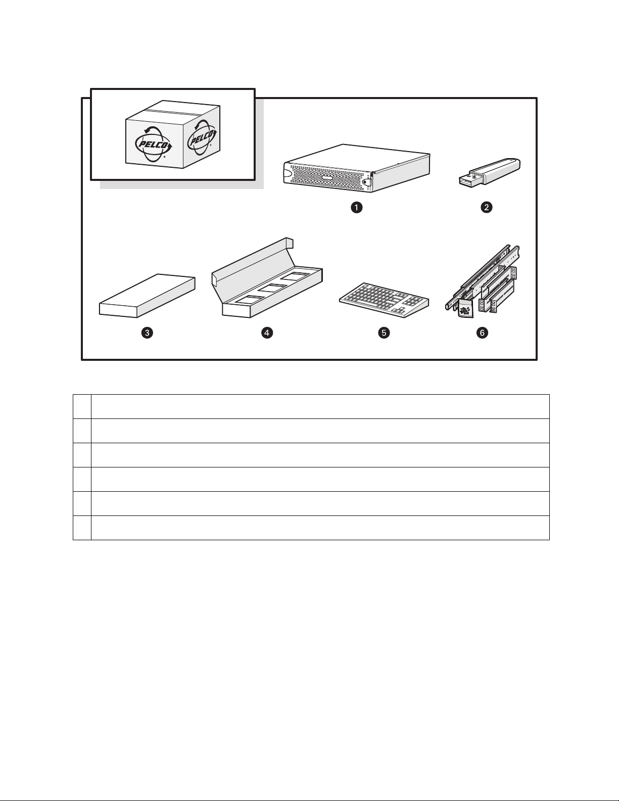
Figure 1: Package Contents
1 System Hardware
2 USB Key: Might include installer software, a recovery image, and the installation and operation manuals.
3 Accessory Pack
4 Hard Drive Pack (hard drives in carriers)
5 Standard USB Keyboard (1 ea. for workstation models only)
6 Rack Mount Kit (1 ea.)
5
Page 6
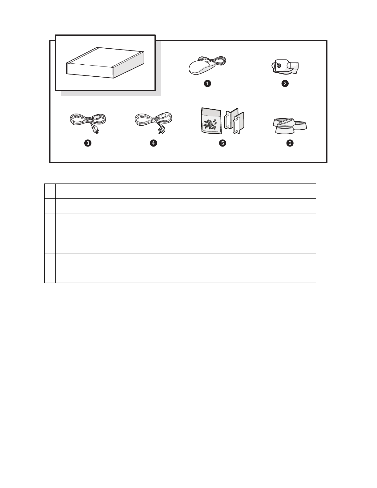
Figure 2: Accessory Pack Contents
1 Standard USB Mouse (1 ea.)
2 Bezel Keys (2 ea.)
3 Standard US Power Cord (1 ea.)
4 Power Cord (based on country designation, 1 ea.)
NOTE: Units shipped to China do not include power cords.
5 Chassis Handles (2 ea.); includes Phillips screws for installation.
6 Rubber Feet (4 ea.)
6
Page 7
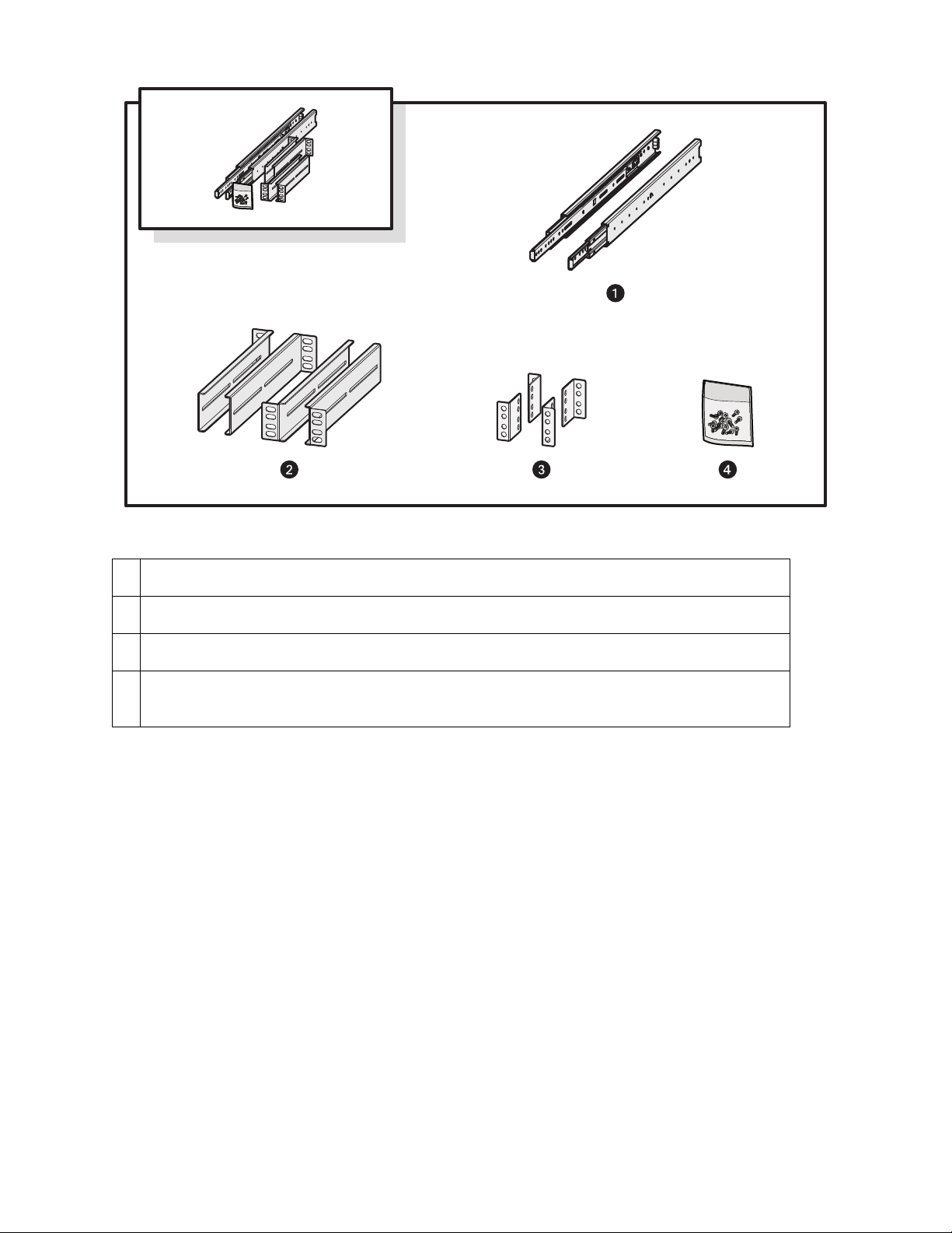
Figure 3: Rack Mount Kit Contents
1 Sliding Mounting Brackets (2 ea.)
2 Rear Mount Rails (2 ea.), Front Mount Rails (2 ea.)
3 L-Shaped Plate Nuts (4 ea.)
4 M5*8L-H2.5 Round Head Nickel Screws (18 ea.), M4*6L-H2.5 Round Head Nickel Screws (18 ea.), 4.2*11*0.8
Nickel Washers (10 ea.)
Tools and Parts Required for Installation
The following installation tools and parts are needed for installation, but are not supplied.
• Power source (110/220 VAC)
• Small Phillips screwdriver, if mounting the unit into a rack
7
Page 8
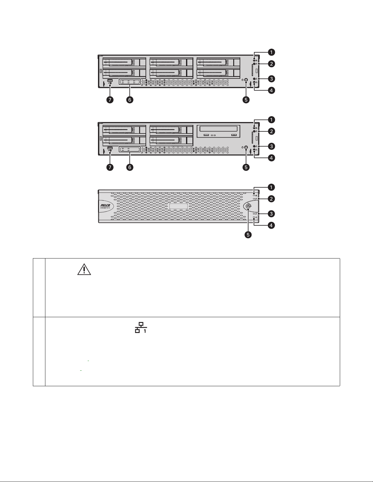
Product Overview: Front
Figure 1: Server Models: Front Panel Layout (Bezel Open)
Figure 2: Workstation Models with-DVD: Front Panel Layout (Bezel Open)
Figure 3: Front Bezel Indicators (Bezel Closed)
1
Unit Status
• Green: The unit is functioning normally.
• Flashing green: The unit is starting or shutting down.
• Amber: The unit is nearing operational thresholds; maintenance is recommended.
• Red: The unit is in an error condition.
2
Network Port 1 Speed and Activity
• Off: The unit is not connected to the network.
• Solid green: The unit is connected to the network using the 1000Base-T standard.
• Solid amber:
• Solid red:
NOTE: Use the 1000Base-T standard.
The unit is connected to the network using the 100Base-T standard.
The unit is connected to the network using the 10Base-T standard.
8
Page 9

3
Network Port 2 Speed and Activity
The unit is not connected to the network.
• Off:
• Solid green:
• Solid amber:
• Solid red:
NOTE: Use the 1000Base-T standard.
The unit is connected to the network using the 1000Base-T standard.
The unit is connected to the network using the 100Base-T standard.
The unit is connected to the network using the 10Base-T standard.
4
Software Status
• Green:
The software is operating normally.
• Amber: A minor software malfunction is detected (for example, an excessive network packet loss).
• Red:
5
Power Button
A fatal software error has occurred (for example, ceasing to record).
• Push the power button to turn the unit on or off.
• Push and hold the power button for a hard shutdown.
6 Drive Status
• Flashing green: The read or write activity on a specific hard drive.
• Solid red: A problem exists with the hard drive.
• Flashing green/red: The unit is initializing the hard drive
7 USB Ports
The unit has five USB ports: one on the front panel (USB 2.0 port) and four on the rear panel (two USB 3.0 and two USB 2.0 ports).
Use these ports to connect a UPS unit, or conduct diagnostic and troubleshooting activities.
9
Page 10

Product Overview: Rear
1 Rear Chassis Fan
2 Power Receptacle
3 VGA Port
4 Ethernet Ports
• Network Port 1 (left is primary)
• Network Port 2 (right is secondary)
Figure 1: Rear Panel Layout
5 Expansion Slots
6 Serial Ports
7 Reserved (do not use)
8 Audio Output
9 Audio Input
10 USB 3.0 Ports
11 USB 2.0 Ports
12 DisplayPort Connectors
13 Digital Visual Interface (DVI) Connector
Placing on a Desktop
WARNING: Do not place the unit on its side; in this position, the unit is likely to fall over and may cause equipment damage or personal
injury.
1. Verify that the rubber feet are attached to the bottom of the unit. If not, secure the rubber feet to the bottom of the unit.
2. Position the unit to allow for cable and power cord clearance at the rear.
10
Page 11

Mounting Requirements
The unit can be mounted in an industry standard 48 cm (19-inch) equipment rack and occupies two rack units (RU) of vertical rack space
(8.9 cm or 3.5 inches). The hardware necessary to mount the unit into a rack is supplied with the unit.
NOTE: The unit must be placed on a desktop to install an optional 4-port capture card, a RAID controller card, or a SCSI card. Make sure
these cards are installed properly and performing as expected before placing the unit in the rack.
The rack must meet the following requirements:
• Rack standard:48 cm (19 in.), EIA-310-D compliant (rear column required)
• Rack column depth:50.8 to 76.2 cm (20 to 30 in.)
• Column mounting hole provisions:10-32 UNF-2B threaded holes or square window holes on front and rear columns
• Door systems (optional): Front doors must have at least 5.1 cm (2 in.) between the unit bezel and the inside of the door. Rear
doors may be used only on rack columns that are more than 66 cm (26 in.) deep.
Mounting in a Rack
Do not block slots and openings in the cabinet. These provide ventilation to prevent the unit from overheating. Never place the unit near
or over a radiator or heat register. When placing the unit in a rack, be sure to provide proper ventilation.
1. Install the chassis handles:
a. Align the screw holes on the chassis handles and the chassis.
b. Insert and tighten the four 10-32 x 0.5-inch Phillips flat head screws with a Phillips screwdriver.
2. Remove the chassis brackets from the sliding brackets:
a. Slide each chassis bracket away from the sliding bracket until it locks in place.
b. Press the release lever up or down (depending on the rail) to release the chassis bracket from the sliding bracket. Press down
on the release lever for the right set of rails and press up for the left set of rails.
Figure 1: Remove the Chassis Brackets from the Sliding Brackets
11
Page 12

3. Attach one chassis bracket to each side of the unit. Use four M4*6L-H2.5 round head nickel screws for each bracket. Attach the
chassis brackets so that the slotted ends are positioned toward the rear of the unit.
Figure 2: Attach the Mounting Brackets
4. If necessary, remove the rubber feet from the underside of the unit.
5. Attach a front and rear L-shaped bracket to the left and the right sliding brackets using two M4*6L-H2.5 round head nickel screws.
Leave all eight of the screws untightened.
Figure 3: Attach the L-Shaped Mounting Brackets
6. Attach the front and rear L-shaped brackets to the rack. Make sure the rails are mounted back to back. Use two M5*8L-H2.5 round
head nickel screws for each bracket.
The mounting brackets are identical and can be used on either side of the rack.
a. Position the ear of the front L-shaped bracket and an L-shaped plate nut against the inside front of the equipment rack. Align
the two center holes in the ear of the L-shaped bracket and L-shaped plate nut with the holes in the rack.
b. Using two M5*8L-H2.5 round head nickel screws, insert and tighten the screws from the outside of the rack, pointing toward
the back of the rack.
c. Adjust the rails to the correct depth of the equipment rack by sliding the rear-mount rail to the back of the equipment rack.
d. Repeat the previous steps to attach the rear L-shaped bracket and L-shaped plat nut to the rack.
12
Page 13

Figure 4: Attach the Brackets to the Rack
7. Tighten the M4*6L-H2.5 round head nickel screws that are attached to the front- and rear-mount rails which were left untightened
earlier in the installation.
8. Place the unit onto the mount rails by sliding the chassis brackets onto the rails. Align the chassis brackets with the first slot on the
sliding brackets when installing the unit. This will ensure that the two brackets are aligned properly when sliding the unit in and
out of the rack. It might require two people to lift and slide the unit into place.
NOTE: To pull the unit completely out of the rack, pull the unit out of the sliding bracket until it locks into place, and then press the
release levers on either side of the chassis bracket to release the unit.
Figure 5: Install the Unit in the Rack
Figure 6: Align the Chassis Bracket and the Sliding Bracket
9. Insert and tighten two M5*8L-H2.5 round head nickel screws above and below the chassis handles to secure the unit in the rack.
13
Page 14

Installing the Drive Array
Drives and drive bays are numbered 1 through 6. You must install the drives in their corresponding bays in numerical order.
When replacing a drive in a RAID array, you should rebuild the array before operating. If another drive fails before the array is rebuilt,
the array will go off line and data loss will occur.
WARNING: The hard drive parts and assemblies are susceptible to damage by Electrostatic Discharge (ESD). Follow safe handling proce-
dures when replacing hard drives.
Figure 1: Drive Bay Allocation for Models with 6 Bays
1 SSD; contains the OS
2 SSD; RAID 1 OS
3 HDD; RAID 5 Export Storage
4 HDD; RAID 5 Export Storage
5 HDD; RAID 5 Export Storage
6 HDD; RAID 5 Export Storage
Figure 2: Drive Bay Allocation for Models with DVD Drive
1 SSD: Contains operating system, install first
2 HDD: for additional storage (optional)
3 HDD: for additional storage (optional)
4 HDD: for additional storage (optional)
5 DVD drive
14
Page 15

1. Unlock and open the bezel.
2. Install the drive carriers:
a. Open the drive latch (grasp the latch right side and pull it to the left).
b. Slide the drive carrier into the drive bay.
c. Close the hard drive latch; ensure that the drive carrier locks into place.
3. Close and lock the bezel.
15
Page 16

Connecting the Power Supply
UPS
POWER SOURCE
INPUT POWER
USB
OUTPUT POWER
1. Connect the power cord to the unit’s power connector.
2. Connect the other end of the power cord to the appropriate power source.
Connecting an Uninterruptible Power Supply
While UPS units supply backup battery power, the unit works in conjunction with the SmartUPS from APC. The SmartUPS signals the
unit to begin a graceful shutdown if the UPS standby power falls below a specific threshold.
1. Shut down the unit.
2. Connect a power cord from the unit power supply to a standard wall outlet.
3. Connect a power cord from the UPS to a standard wall socket or other power source.
4. Connect a USB cable from the APC SmartUPS to the USB connector on the unit.
5. Turn on the UPS.
6. Turn on the unit.
16
Figure 1: Connecting a UPS
Page 17

Starting Up the Unit
1. Unlock and open the bezel.
2. Press the power button.
3. Close and lock the bezel.
Shutting Down the Unit
Use an orderly shutdown for the unit to close files and power down.
Use the immediate shutdown in an emergency or when there is not enough time for an orderly shutdown.
Orderly Shutdown
1. Click Start.
2. Click Shut Down.
Immediate Shutdown
1. Unlock and open the bezel.
2. Press and hold the power button until the unit shuts down.
3. Close and lock the bezel.
17
Page 18

Connecting to the Network
SECONDARY
NETWORK
The primary network interface card (NIC) must be active when using the License Key Entry program to add or update IP camera licenses.
1. Connect one end of an Ethernet cable one of the unit’s network interfaces.
2. Connect the other end of the cable to an available Gigabit Ethernet port.
Figure 1: Network Cable Connection
18
Page 19

Migrating Data to a SM5200 from a SM5000
You must configure the network interface and DHCP settings on the SM5200 to match the settings from the SM5000 before performing
the migration process, or you will lose these settings in the migration process.
For a quick and seamless transition to a new system manager, you can transfer your database and settings from your existing SM5000
to a new SM5200.
The migration process requires a flash drive with an empty boot record and a Windows-based client on the Endura network with Endura
Utilities version 2.3.3 or later installed. It is recommended that you use the Pelco flash drive included with your SM5000 for data migration.
Data migration does not include primary network interface settings or settings for features new and specific to the SM5200. You must
manually configure these settings.
Do not replace your existing system manager until your SM5200 is fully configured and operational. Only the admin user can log on to
the SM5200. If the admin user exists in the database you are migrating to the SM5200, the user will login to the SM5200 using his or
her current password. If the admin user does not exist before migration, then the admin user will login using the default password.
1. Connect your Pelco flash drive to a Windows-based client on the Endura network.
2. Open Endura Utilities.
3. Right-click SM5000 in the System Attributes tab.
4. Select SM Backup.
5. Select the flash drive as the backup location and click OK. This creates a folder on the flash drive named the IP address of the
SM5000 you are backing up. The folder will contain a UtilitiesBackup.tgz file.
6. Copy UtilitiesBackup.tgz to the root directory of the flash drive.
7. Remove the flash drive from the client computer, and connect it to the SM5200.
8. Turn on the SM5200. After a short boot process, the four lights on the right side of the unit’s front panel turn solid amber, indicating
that the system is importing UtilitiesBackup.tgz. This process may take several minutes.
9. Remove the flash drive when the software status light turns off, indicating that the migration process is complete. The SM5200
restarts 30 seconds after the migration process has completed. Remove the flash drive within 30 seconds of the completed migration process or once the unit has fully rebooted; do not remove the flash drive during the boot process.
NOTE: Upon completing the migration process, the SM5200 creates a file called .sm5000-migrated in the root directory of the flash
drive, preventing the SM5200 from attempting to import UtilitiesBackup.tgz multiple times.If data fails to migrate properly, or you
want to reuse the flash drive to perform the migration process on another SM5200, delete the.sm5000-migrated file.
19
Page 20

Technical Specifications
Hardware
Processor
Internal Memory
SM5200 16 GB DDR3 RAM ECC
WS5080 8 GB DDR3 RAM Non-ECC
Operating System
SM5200 Embedded Linux
WS5080 Windows 7 Ultimate 64-bit SP1
Storage
SSD 120 GB (OS)
HDD 4 TB
Drive Bays
SM5200 6 (2 SSD in RAID1, up to 4 HDD)
WS5080 4 (1 SSD, 3 Unused)
Optical Drive DVD±RW (WS5080 only)
USB Ports 3 USB 2.0 ports (1 front, 2 rear), 2 USB 3.0 ports (rear)
®
Intel
Xeon® E3-1275 v3
Video
Video System Intel HD Graphics P4700 (shared memory)
Max Resolution 3840 x 2160 per DisplayPort output (2x)
1920 x 1200 @ 60 hz on DVI-D output
1920 x 1200 @ 60 hz on VGA output
Video Outputs Supports up to 3 simultaneous displays using any combination of the four outputs
Video Standards 60 Hz capable for NTSC
75 Hz capable for PAL
Video Decoding Supported MPEG-4 ASP; H.264 Baseline, Main, and High profiles
Video Display Modes 1 image, 4 images (2 x 2), 9 images (3 x 3), 16 images (4 x 4), 6 images (1 large + 5 small), 10 images (2
large + 8 small), 13 images (1 large + 12 small); High definition monitors can also display 6 images (3 x 2)
and 12 images (4 x 3)
Decoding Performance 16X real-time MPEG-4 streams at 704 x 480; 12X real-time H.264 Baseline profile streams at 704 x 480;
4X H.264 Baseline profile streams at 720p; 2X real-time H.264 Baseline profile streams at 1080p
Audio
Audio Decoding G.711 speech codec
Audio Bit-rate 64 kbps
Audio Levels
Input Electret microphone
Output Up to 3 Vp-p, adjustable, minimum load of 8 ohms
Audio Connectors 2, 3.5 mm stereo jacks
Connector Tip Signal left (input and output)
Connector Ring Signal right (input and output)
20
Page 21

Audio
Connector Sleeve Common
Audio Inputs Microphone
Audio Outputs Speaker or line out
Network
Interface 2 Gigabit Ethernet RJ-45 port (1000Base-T)
Front Panel
Buttons
Indicator
Unit Status Green, amber, red
Primary Network Green, amber, red
Secondary Network Green, amber, red
Software Status Green, amber, red (based on diagnostics)
Hard Disk Status Green, red, off (behind bezel)
Power
Power Input 100 to 240 VAC, 50/60 Hz, autoranging
Power Supply Internal
Power Consumption Operating Maximum
100 VAC 160 W, 1.60 A, 547 BTU/H
115 VAC 160 W, 1.39 A, 547 BTU/H
220 VAC 160 W, 0.72 A, 547 BTU/H
Environmental
Operating Temperature 10° to 35°C (50° to 95°F) at unit air intake (front of unit)
Storage Temperature –40° to 65°C (–40° to 149°F)
Operating Humidity 20% to 80%, noncondensing
Maximum Humidity Gradient 10% per hour
Operating Altitude –15 to 3,048 m (–50 to 10,000 ft)
Operating Vibration 0.25 G at 3 Hz to 200 Hz at a sweep rate of 0.5 octave/minute
NOTE: The temperature at the unit air intake can be significantly higher than room temperature. Temperature is affected by rack configura-
tion, floor layout, air conditioning strategy, and other issues. To prevent performance failure and unit damage, make sure the temperature
at the unit is continuously within the operating temperature range.
Physical
Construction Steel cabinet
Finish
Front Panel Gray metallic with black end caps
Chassis Black matte finish
Dimensions 50.8 x 43.4 x 8.9 cm (20" D x 17.1" W x 3.5" H)
21
Page 22

Physical
Mounting Desktop (feet) or rack (2 RU per unit)
SM5200 Models
Use the following table to create a model number for your SM5200. For example, the model number for an SM5200 with 4 TB of storage
and a United Kingdom power cord would be SM5200-04-UK.
Model Storage Country Code Description
4 TB US = North America
AU = Australia
SM5200 hardware/software with regional power cord
SM5200
AR = Argentina
16 TB EU = Europe
UK = United Kingdom
CN = China
SM5200 hardware/software without power cord. Units shipped to China do not include a
power cord.
WS5080 Models
Use the following table to create a model number for your WS5080. For example, the model number for a WS5080 workstation with a
United Kingdom power cord would be WS5080-UK.
Model Country Code Description
US = North America
AU = Australia
WS5080 hardware/software with regional power cord
WS5080
AR = Argentina
EU = Europe
UK = United Kingdom
CN = China
WS5080 hardware/software without power cord. Units shipped to China do not include a power
cord.
Supplied Accessories
Keyboard
Mouse
USB Drive containing Resource and Recovery materials
Windows 7 Ultimate Disc with License (WS5080 Only)
Rack Mount Kit
Power Cord
NOTE: Units shipped to China do not include power cords.
Optional Software Accessories
WS5200-MAP Endura Mapping interface
Certifications
CE, Class A
FCC, Class A
UL/cUL Listed
22
Page 23

Certifications
S-Mark for Argentina
CCC
C-Tick
Standards/Organizations
Pelco is a member of the MPEG-4 Industry Forum
Pelco is a member of the Universal Plug and Play (UPnP) Forum, Steering Committee
Pelco is a member of the Universal Serial Bus (USB) Implementers Forum
Pelco is a contributor to the International Standards for Organization / Electrotechnical Commission (ISO/IEC) Joint Technical Committee 1
(JTC1), “Information Technology,” Subcommittee 29, Working Group 11
Compliance, ISO/IEC 14496 standard (also known as MPEG-4)
Compliance, International Telecommunication Union (ITU) Recommendation G.711, “Pulse Code Modulation (PCM) of Voice Frequencies”
23
Page 24

Pelco by Schneider Electric
3500 Pelco Way Clovis, California 93612 USA
(800) 289-9100 Tel (800) 289-9150 Fax
+1 (559) 292-1981 International Tel
+1 (559) 348-1120 International Fax
www.pelco.com
Pelco, the Pelco logo, and other trademarks associated with Pelco products referred to in this publication are trademarks of Pelco, Inc. or its affiliates. © Copyright 2014, Pelco, Inc.
ONVIF and the ONVIF logo are trademarks of ONVIF Inc. All other product names and services are the property of their respective companies. All rights reserved.
Product specifications and availability are subject to change without notice.
 Loading...