

Page 1
INSTALLATION
WMVE Series Rugged Wall Mounts
C2253M-B (1/14)
Page 2

Important Notices
IMPORTANT SAFETY INSTRUCTIONS
1. Read these instructions.
2. Keep these instructions.
3. Heed all warnings.
4. Follow all instructions.
5. Only use attachments/accessories specified by the manufacturer.
6. Installation should be done only by qualified personnel and conform to all local codes.
7. Use only installation methods and materials capable of supporting four times the maximum
specified load.
8. Only use replacement parts recommended by Pelco.
WARRANTY STATEMENT
For information about Pelco’s product warranty and thereto related information, refer to
www.pelco.com/warranty.
2 C2253M-B (1/14)
Page 3

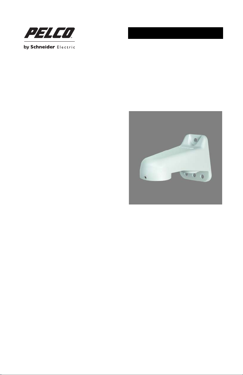
Description
The WMVE-SR, WMVE-WT, and WMVE-SW are wall mounts that can be installed directly to a wall or any
vertical surface. Power and video wiring can be easily routed through the back of the mounts or through
the conduit access located on the bottom of the mount arms. The wall mounts can also be pole mounted
using a PA101 pole mount adapter.
MODELS
WMVE-SR Environmental light gray wall mount specifically designed for use with the IMEx19-1VP,
IMEx19-1EP, IM-VEPM, IMPBB-EP, IE-P, and Camclosure
WMVE-WT White wall mount specifically designed for use with the ID-P indoor pendant mount.
WMVE-SW White wall mount specifically designed for use with the IMEx19-1P and IMPBB-P indoor
pendant mounts.
PARTS LIST
WMVE-SR/WMVE-WT
The following installation tools and parts are supplied:
Qty Description
1 WMVE-SR or WMVE-WT wall mount
1 Tube of anti-seize lubricant
1 Wall mount gasket
1 Installation manual
WMVE-SW
The following installation tools and parts are supplied:
Qty Description
1 WMVE-SW wall mount
1 1½-inch NPT to 3/4-inch NPT adapter
1 3/4-inch NPT nut
1 Tube of anti-seize lubricant
1 Wall mount gasket
1 Installation manual
®
2 Series pendant mounts.
USER SUPPLIED PARTS LIST
Qty Description
1 Pendant mount
1 Wrench, 5/64-inch, hex Allen
2 to 4 Fasteners, 1/4-inch, of appropriate type based on installation
C2253M-B (1/14) 3
Page 4

Installation
INSTALLING THE WALL MOUNT
STANDARD INSTALLATION
1. Using the wall mount as a template, mark the fastener positions on the mounting surface.
2. Prepare the mounting surface.
3. Install the wall mount gasket:
a. Remove the five foam pieces from the gasket.
b. Remove the backing paper from the gasket.
c. Align the holes in the gasket with the holes in the wall mount and attach the adhesive side of
the gasket to the wall mount support.
4. Route the system power and video wiring through the wall mount.
5. Use a minimum of two 1/4-inch fasteners of appropriate type (not supplied) to secure the wall
mount to the mounting surface.
NOTE: (Outdoor installations only) Seal the fastener holes with an appropriate sealant (not supplied)
to prevent water damage. Be sure to apply the sealant between the mount and the mounting surface.
Figure 1. Installing the Wall Mount
CONDUIT INSTALLATION
1. Using the wall mount as a template, mark the fastener positions on the mounting surface.
2. Prepare the mounting surface.
3. Install the wall mount gasket:
a. Remove the five foam pieces from the gasket.
b. Remove the backing paper from the gasket.
c. Align the holes in the gasket with the holes in the wall mount and attach the adhesive side of
the gasket to the wall mount support.
4 C2253M-B (1/14)
Page 5

4. Remove the conduit cover from the bottom of the mount arm.
5. Thread a 3/4-inch or 25 mm conduit fitting (not supplied) into the conduit hole located at the bottom
of the mount arm.
6. Route the wiring/cabling through the mount arm.
7. Use a minimum of two 1/4-inch fasteners of appropriate type (not supplied) to secure the wall
mount to the mounting surface (refer to Figure 1).
NOTE: (Outdoor installations only) Seal the fastener holes with an appropriate sealant (not supplied)
to prevent water damage. Be sure to apply the sealant between the mount and the mounting surface.
INSTALLING THE PENDANT MOUNT: WMVE-SR/WMVE-WT
1. Route the wiring through the pendant mount (not supplied).
2. Apply anti-seize lubricant (supplied) to the threads of the pendant mount.
3. Screw the pendant mount onto the mount arm.
4. Use a 5/64-inch hex Allen wrench (not supplied) to tighten the setscrew located on the front of the
wall mount.
Figure 2. Installing the Pendant Mount: WMVE-SR/WMVE-WT
INSTALLING THE PENDANT MOUNT: WMVE-SW
1. Route the wiring through the 1½-inch NPT to 3/4-inch NPT pendant mount adapter (supplied).
2. Apply anti-seize lubricant (supplied) to the threads of the pendant mount adapter.
3. Screw the pendant mount adapter onto the mount arm.
4. Use a 5/64-inch hex Allen wrench (not supplied) to tighten the setscrew located on the front of the
wall mount.
5. Route the wiring through the pendant mount (not supplied).
6. Insert the pendant mount adapter through the top of the pendant mount, and secure in place by
tightening the 3/4-inch NPT nut (supplied).
C2253M-B (1/14) 5
Page 6

Figure 3. Installing the Pendant Mount: WMVE-SW
Specifications
MECHANICAL
Mounting Method Secure with 1/4-inch fasteners of appropriate type (not supplied);
Cable Entry Through the back of the mount and one 3/4-inch or 25 mm conduit
GENERAL
Construction Aluminum
Finish
WMVE-SR Light gray polyester powder coat
WMVE-WT, WMVE-SW White polyester powder coat
Unit Weight 0.45 kg (1.00 lb)
NOTE: VALUES IN PARENTHESES ARE INCHES; ALL OTHERS ARE CENTIMETERS.
up to 4 fasteners can be used.
access on the bottom of the mount.
16.59 (6.53) 7.42 (2.92)
9.40 (3.70)
6 C2253M-B (1/14)
Page 7

This equipment contains electrical or electronic components that must be recycled properly to comply with Directive
2002/96/EC of the European Union regarding the disposal of waste electrical and electronic equipment (WEEE).
Contact your local dealer for procedures for recycling this equipment.
REVISION HISTORY
Manual # Date Comments
C2253M 1/11 Original version.
C2253M-A 7/13 Added model WMVE-SW, 1½-inch NPT to 3/4-inch NPT adapter, and 3/4-inch NPT nut.
C2253M-B 1/14 Added gasket assembly procedure.
Pelco, the Pelco logo, and other trademarks associat ed with Pelco products referred to in this publication are trademarks of Pelco, I nc. or its affiliates.
All other product names and services are the property of their respective companies. ONVIF and the ONVIF logo are trademarks of ON VIF Inc.
Product specifications and availability are subject to change without notice. © Copyright 2014, Pelco, Inc. All rights reserved.
Removed Product Warranty and Return Information; replaced with Warranty Statement.
Page 8

Pelco by Schneider Electric 3500 Pelco Way Clovis, California 93612-5699 United States
USA & Canada Tel (800) 289-9100 Fax (800) 289-9150
International Tel +1 (559) 292-1981 Fax +1 (559) 348-1120
www.pelco.com www.pelco.com/community
 Loading...