

IR850, IR940 & WLED
LED ILLUMINATORS
C3934M (9/13)

Contents
Important Safety Instructions ............................................................................ 3
Important Notices
Regulatory Notices .................................................................................... 4
Radio and Television Interference..............................................................4
Installation Steps – Quick Guide ....................................................................... 5
Complete Set up and Installation ...................................................................... 6
Remote Controller ............................................................................................. 8
LED Status Feedback System .......................................................................... 9
Standard Bracket Dimension Drawings ............................................................ 10
Optional Mounting Bracket ............................................................................... 11
Optional Mounting Bracket Dimension Drawings ............................................. 11
Optional Interchangeable Diffuser System ....................................................... 12
Specifications .................................................................................................... 13
Certifications and Ratings ................................................................................. 13
Illuminator Dimension Drawings ....................................................................... 14
Troubleshooting Guide ...................................................................................... 17
2 www.pelco.com C3934M (9/13)

Important Safety Instructions
1. Read these instructions.
2. Keep these instructions.
3. Heed all warnings.
4. Follow all instructions.
5. Do not use this apparatus near water.
6. Clean only with dry cloth.
7. Do not block any ventilation openings. Install in accordance with the manufacturer’s
instructions.
8. Only use attachments/accessories specified by the manufacturer.
9. Refer all servicing to qualified service personnel. Servicing is required when the
apparatus has been damaged in any way, such as power-supply cord or plug is
damaged, liquid has been spilled or objects have fallen into the apparatus, the
apparatus has been exposed to rain or moisture, does not operate normally, or has
been dropped.
10. Installation should be done only by qualified personnel and conform to all local codes.
11. Unless the unit is specifically marked as a NEMA Type 3, 3R, 3S, 4, 4X, 6, 6P
enclosure or marked as suitable for use in wet locations, it is designed for indoor use
only and it must not be installed where exposed to rain and moisture.
12. Use only installation methods and materials capable of supporting four times the
maximum specified load.
13. Use stainless steel hardware to fasten the mount to outdoor surfaces.
CAUTION: These servicing instructions are for use by qualified service personnel only.
To reduce the risk of electric shock do not perform any servicing other that contained in
the operating instructions unless you are qualified to do so.
CAUTION: IR emitted from this product – Risk Group 2. Avoid prolonged eye exposure
or use appropriate shielding or eye protection at distances of less than 1500mm.
Risk Group 2 for cornea/lens infrared hazard. At a distance of more than 1500mm for all
IR850 products or 1300mm for all IR940 products the unit is in the exempt group.
3www.pelco.comC3934M (9/13)

Important Notices
REGULATORY NOTICES
This device complies with Part 15 of the FCC Rules. Operation is subject to the
following two conditions: (1) this device may not cause harmful interference, and (2)
this device must accept any interference received, including interference that may
cause undesired operation.
RADIO AND TELEVISION INTERFERENCE
This equipment has been tested and found to comply with the limits of a Class B
digital device, pursuant to Part 15 of the FCC Rules. These limits are designed to
provide reasonable protection against harmful interference in a residential installation.
This equipment generates, uses, and can radiate radio frequency energy and,
if not installed and used in accordance with the instructions, may cause harmful
interference to radio communications. However there is no guarantee that the
interference will not occur in a particular installation. If this equipment does cause
harmful interference to radio or television reception, which can be determined
by turning the equipment off and on, the user is encouraged to try to correct the
interference by one or more of the following measures:
• Reorient or relocate the receiving antenna.
• Increase the separation between the equipment and the receiver.
• Connect the equipment into an outlet on a circuit different from that to which the
receiver is connected.
• Consult the dealer or an experienced radio/TV technician for help.
You may also find helpful the following booklet, prepared by the FCC: “How to Identify
and Resolve Radio-TV Interference Problems.” This booklet is available from the U.S.
Government Printing Office, Washington D.C. 20402.
Changes and Modifications not expressly approved by the manufacturer or registrant
of this equipment can void your authority to operate this equipment under Federal
Communications Commission’s rules.
This Class B digital apparatus complies with Canadian ICES-003.
Cet appareil numérique de la classe B est conforme à la norme NMB-003 du Canada.
WARRANTY STATEMENT
For information about Pelco’s product warranty and thereto related information, refer to
www.pelco.com/warranty
4 www.pelco.com C3934M (9/13)
Installation Steps – Quick Guide
1. IR850, IR940 & WLED Illuminators are factory set
and delivered with a 35˚ beam width. To alter
to 10˚, simply remove Interchangeable Diffuser
System (IDS) lens. To alter to 60˚, replace
with the other IDS lens supplied. See detailed
instructions later in this document.
2. Mount Illuminator.
3. Connect the Illuminator to a properly rated low
voltage power supply
(12-24V AC/DC).
4. Complete configuration and final set-up
using Remote Controller (this is an optional
accessory).
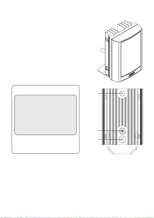
Wiring - six core cable
Black: AC/DC-
Red: AC/DC+
White: Photocell Following Contact
Yellow: Photocell Following Contact
Orange: Telemetry Input
Purple: Telemetry Input
(1) Volt Free Output; Non-polarity sensitive
(2) Volt Free/Dry Contact or TTL Input
(see step 4 for more details)
(2)
(2)
Photocell
(1)
(1)
Cable
Breather
Gland
Factory Default Set-Up:
35˚ Beam Angle
Max 100% Power
Telemetry Input - closed
Photocell sensitivity - MID
Status LEDs – ON
Programming function will auto-disable after 4 weeks
5www.pelco.comC3934M (9/13)
Complete Set up and Installation
Step 1. Select different beam angle – if required
All IR850, IR940 & WLED illuminators are set and delivered with a 35˚ beam width
angle. To alter to 10˚, simply remove Interchangeable Diffuser System (IDS) lens.
To alter to 60˚, replace with additional IDS lens supplied.
Other angle IDS lenses are available to order: 80˚ and 120˚.
All IDS lenses will be clearly marked with the angle which they will produce when
inserted into IR850, IR940 or WLED illuminator.
Please handle IDS lenses with care – and do not touch optical film.
Only 1 IDS lens can be inserted into the product at anytime. The product cannot
accommodate multiple IDS lenses at the same time.
We would recommend that power is turned off when replacing IDS lenses.
Remove base plate from unit using 2.5mm allen/hex key. Remove any IDS lens
currently installed and insert the required IDS lens.
Re-attach the base.
IMPORTANT NOTE: Ensure that the gasket is correctly located and the screws
fastened tightly to ensure and maintain IP66 rating of the product.
6 www.pelco.com C3934M (9/13)

Step 2. Mounting Illuminator
All IR850, IR940 & WLED illuminators are delivered as standard with the bracket at
the bottom of the unit. This can be moved to the top of the unit if required.
1 2 3
Position illuminator adjacent
to camera and point
towards scene (Optional
night set-up for optimum
image performance)
Adjust vertical position of
lamp to ensure full field of
view illuminated
Tighten all fixings
Step 3. Connect to low voltage power supply and input 12-24 AC/DC
The illuminator is operational with 12V to 24V DC or AC voltage. When using DC
power, the Red wire must be connected to the positive side of the power supply
and the black wire to negative. When using AC power, there is no specific polarity.
Step 4. Telemetry Input plus ‘Dim’ function (Orange & Purple) OPTIONAL
The telemetry input can be used to control the lamp and dim function from an
external source. As a default, the telemetry inputs are wired together for standard
photocell controlled on/off operation.
If required to be activated by an external source, connect as an appropriate volt-free
or TTL input.
Volt free input/dry contact: Non polarity sensitive: Short circuit = light on
TTL input: Orange = TTL +, Purple = TTL (GND)
0V = Light on, 3V = Light off
Step 5. Photocell following output (White & Yellow) OPTIONAL
The Photocell following output can be used to manually control the day/night
operation of a camera. The volt free output is open when the photocell senses
daytime ambient light levels, and is closed when it senses nighttime ambient light
levels.
7www.pelco.comC3934M (9/13)

Remote Controller
Optional Accessory
To select 3 different photocell sensitivity
Power Select
Quick and easy selection
of 5 accurately defined
power settings. Provides
exact amount of light
required for the scene
requirements
Photocell Disable
Lamp operates from
telemetry input only
and ignores status
of photocell
Photocell Adjust
levels to accommodate different
operational requirements
Timer Settings
The timer function allows
the illuminator to be
triggered via the telemetry
input and remain on for a
pre-defined period of time
Timer disable
Selects telemetry input
instead of dim function
on telemetry wires
(default)
Disable Remote
Control Set-Up
Must be depressed for
4 seconds to lock-in
settings and prevent
further alterations
LED Feedback System
Turns Status LED’s On or Off
8 www.pelco.com C3934M (9/13)
Selects dimming
function instead of
telemetry input on
telemetry wires
Restore Factory
Default Settings Must
be depressed for 4
seconds

LED Feedback System
In Programming Mode
Solid Green status LED indicates unit has power
applied. FLASHING GREEN status LED indicates
a problem with the remote control IR receiver. The
maximum remote operating distance is 8m (26ft).
Flashing Amber status LED indicates unit is in
programming mode. Solid Amber indicates unit
receiving valid command from remote control device.
Solid Red status LED indicates an internal LED fault,
and a flashing Red status LED indicates that there is a
problem with the input voltage. Please note: once the
voltage problem has been corrected, the user must
disable remote control set-up or power the unit on and
off to stop the red status LED flashing.
In Normal Operating Mode
Solid Green status LED indicates unit has power
applied. FLASHING GREEN status LED indicates
a problem with the remote control IR receiver. The
maximum remote operating distance is 8m (26ft).
Solid Amber status LED (non flashing) indicates a
problem with the input voltage level. Please note: once
the voltage problem has been corrected, the user must
disable remote control set-up or power the unit on and
off to extinguish the amber status LED.
GREEN
AMBER
RED
GREEN
AMBER
Solid Red status LED indicates an internal LED fault.
RED
9www.pelco.comC3934M (9/13)

Standard Brackets
(not to scale, dimensions rounded to nearest cm)
Small
5.2cm
(2”)
4.7cm
5.6cm
(2.2”)
5.3cm
(2.1”)
(1.8”)
7.2cm
(2.8”)
Medium
Large
5.1cm
(2”)
5.3cm
(2.1”)
10.4cm
(4.1”)
5.3cm
(2.1”)
10 www.pelco.com C3934M (9/13)

Optional Mounting Bracket
LBKT-LED
Bracket for mounting all PELCO LED illuminators to flat surface or wall
Mechanical
Bracket attachment 8.5mm hole diameter (see drawings below)
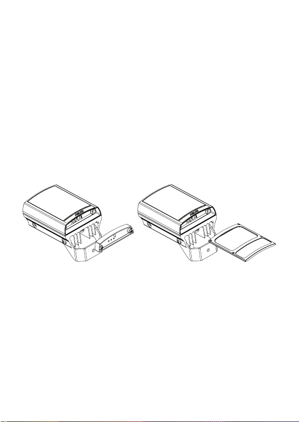
Lamp Mounting Options
Once illuminator(s)
has been mounted to
LBKT, please ensure
to check alignment.
Bottom Mount
Top Mount
Optional Mounting Bracket Dimension Drawings
(not to scale, dimensions rounded to nearest cm)
R1.6cm (0.62”)
2.9cm
(1.14”)
0.85cm
(0.33”)
∅ 0.85cm (0.33”)
0.5cm
(0.19”)
8.9cm
(3.5”)
13.6cm
(5.35”)
0.8cm
(0.31”)
10.5cm
(4.13”)
11www.pelco.comC3934M (9/13)

Optional Interchangeable Diffuser System
LENSPK–LED
Each LENSPK comes with x2 IDS Lenses - 80°x30° and 120°x50°
LENSPKS-LED (Small) LENSPKM-LED (Medium) LENSPKL-LED (Large)
All Pelco LED illuminators are factory set and delivered with a 35˚ beam width
angle.
To alter to 10˚, simply remove Interchangeable Diffuser System (IDS) lens.
To alter to 60˚, replace with other IDS lens supplied.
Other angle IDS lenses are available to order: 80˚ and 120˚.
All IDS lenses will be clearly marked with the angle which they will produce when
inserted into IR850, IR940 or WLED illuminator.
Please handle IDS lenses with care – and do not touch optical film.
Only one IDS lens can be inserted into the product at anytime. The product cannot
accommodate multiple IDS lenses at the same time.
We would recommend that power is turned off when replacing IDS lenses.
Remove base plate from unit using 2.5mm allen/hex key. Insert required IDS lens
and re-attach base plate firmly ensuring gasket is correctly located.
IMPORTANT NOTE:
and the screws correctly fastened to ensure and maintain IP66 rating of the product.
12 www.pelco.com C3934M (9/13)
Ensure base plate is securely seated, the gasket is correctly inserted

Specifications
Infra-Red Series & White-Light Series
Large IR Large WL Medium IR Medium WL Small IR Small WL
220m (10˚) 150m (10˚) 120m (10˚) 90m(10˚) 65m (10˚) 50m (10˚)
120m (35˚) 80m (35˚) 65m (35˚) 55m (35˚) 45m (35˚) 35m (35˚)
Max. Distance
Model dependent
Consumption ~ 48W 24W 12W
Input 12-24V AC or DC 12-24V AC or DC 12-24V AC or DC
Weight 1.9kg (4.1lbs) 1.0kg (2.2lbs) 0.65kg (1.4lbs)
Environment IP66 IP66 IP66
Dimensions
L x W x D
Cable Length 2.5m 2.5m 2.5m
65m (60˚) 45m (60˚) 45m (60˚) 30m (60˚) 30m (60˚) 20m (60˚)
45m (80˚) 30m (80˚) 30m (80˚) 20m (80˚) 20m (80˚) 15m (80˚)
30m (120˚) 20m (120˚) 20m (120˚) 15m (120˚) 15m (120˚) 10m (120˚)
135 x 180 x 68.2 mm
(5” x 7” x 3.2” approx)
100 x 135 x 66mm
(4” x 5” x 2.5” approx)
75 x 100 x 64mm
(3” x 4” x 2.5” approx)
Safety EMC
CE
C22.2 No 250.0-08
UL Listed (UL2108, 8750)
IEC/EN 60529
IEC/EN /AS/NZS 62471
IP66
IK9
EN55022; CISPR22
EN55015; CISPR15
EN50130-4
IEC/EN 61547
FCC
AS/NZSCISPR22
CE
13www.pelco.comC3934M (9/13)

Illuminator Dimension Drawings
Large Units (IR850L-220, IR940L-110 and WLEDL-150)
13.5cm (5.3”)
7.15cm
(2.8”)
18cm (7.1”)
20.05cm (7.9”)
9.47cm (3.7”)
Ø0.85cm (0.3”)
6.82cm (2.7”)
3cm
(1.2”)
Power cable
(Not to scale)
14 www.pelco.com C3934M (9/13)

Medium Units (IR850M-120, IR940M-60 and WLEDM-90)
10cm (3.9”)
4cm
(1.6”)
15.82cm (6.2”)
13.5cm (5.3”)
9.47cm (3.7”)
Ø0.65cm (0.3”)
6.6cm (2.6”)
Power cable
(Not to scale)
3cm
(1.2”)
15www.pelco.comC3934M (9/13)

Small Units (IR850S-65, IR940S-30 and WLEDS-50)
7.5cm (3.0”) 6.41cm (2.5”)
1.4cm
(0.6”)
10cm (3.9”)
11.95cm (4.7”)
9.3cm (3.7”)
Ø0.65cm (0.3”)
Power cable
(Not to scale)
3cm
(1.2”)
16 www.pelco.com C3934M (9/13)

Troubleshooting Guide
Ensure all tests are undertaken by qualified personnel and ensure safe working
practices are followed at all times.
Step 1: Basics
• Check polarity of Lamp connection Red= +, Black= Gnd
• Ensure power is 12-24V AC or DC
• Ensure telemetry wires are shorted or closed contact input (zero volt) is applied.
• Check photocell is working. Cover photocell fully, light should turn on. It is difficult
to see 850nm Infra-Red lamps working in high brightness conditions and not
possible for the human eye to see 940nm.
• Ensure power supply is suitably rated to product – see specifications in the
previous section.
• If longer cables are used, ensure sufficient voltage is provided to allow for drops
across the cable.
Step 2: Lamp Test
• Check that the proper amount of current is being drawn (amount will depend
on power setting of unit. Please note to use the appropriate multimeter setting
depending on how the unit is being powered (AC or DC).
• To test this, you must ensure that the photocell is fully covered (or disabled using
optional remote controller) and ensure telemetry wires are shorted out or closed
contact input (zero volt) is applied.
Step 3: Set up camera, lens, and illumination
• Check model number to Pelco performance specification to ensure required
distance is achievable.
• Check unit is set to max power.
• Check orientation of unit and ensure it is pointing in correct direction.
• Check the angle of unit (IDS) – Too narrow may cause hot spots and the aperture
of the camera lens to close down. Too wide and there may be insufficient light on
scene and light going where it is not needed.
• Check the LED Feedback System – if a flashing red light is visible in programming
mode, please check the input voltage of the unit. The feedback system will
respond differently depending on what mode the unit is in (see below).
17www.pelco.comC3934M (9/13)

Programming mode – (AMBER LED flashes 1 second on/1 second off)
• Solid GREEN - Power Applied
• Flashing GREEN - Remote IR receiver problem
• Solid RED - Internal LED Fault Detected
• Flashing RED - Voltage supply problem detected
- Please note – once the voltage problem has been corrected, the user must
disable remote control set-up or power the unit on and off to stop the red
status LED flashing.
• Solid AMBER - Valid command being received, this remains lit for the duration that
the button on the remote is held. After a valid command has been received the
Amber LED will continue to flash.
Normal operating mode
• Solid GREEN - Unit powered up and operating normally
• Flashing GREEN - Remote IR receiver problem
• Solid RED - Internal LED fault detected
• Solid AMBER - Voltage supply problem detected
- Please note – once the voltage problem has been corrected, the user must
disable remote control set-up or power the unit on and off to extinguish the
amber status LED.
• Check that the unit is responding to the remote. If not, do the following:
- Programming may be disabled. Turn power off/on to ensure unit returns to
programming mode.
- Status indicators may be turned off. Turn on with remote. This can be done
even if programming has been disabled.
- In extreme sunlight conditions, distance between remote and unit may need
to be reduced.
- Battery failure. Check battery on remote (CR2025). Test 3 volt battery, replace
if necessary. Ensure battery has clean contacts.
- Remote failure. Test with new remote.
18 www.pelco.com C3934M (9/13)

Step 4: Call Pelco for further assistance
If the instructions provided fail to solve your problem, contact Pelco Product Support
at 1-800-289-9100 (USA and Canada) or +1-559-292-1981 (international) for
assistance. Be sure to have the serial number available when calling.
Do not try to repair the unit yourself. Leave maintenance and repairs to qualified
technical personnel only.
19www.pelco.comC3934M (9/13)

Pelco by Schneider Electric 3500 Pelco Way, Clovis, California 93612-5699 United States
USA & Canada Tel (800) 289-9100 Fax (800) 289-9150
International Tel +1 (559) 292-1981 Fax +1 (559) 348-1120
www.pelco.com www.pelco.com/community
C3934M (9/13)
 Loading...