

Page 1
®
INSTALLATION/OPERATION
VSS200DT
Screen Splitter
C627M-A (8/03)
Page 2
GENERAL
IMPORTANT SAFEGUARDS AND WARNINGS
DESCRIPTION
Observe the following WARNINGS before installing and using this product.
1. Installation and servicing should be done only by qualified service personnel and conform to all local codes.
2. Unless the unit is specifically marked as a NEMA Type 3, 3R, 3S, 4, 4X, 6, or 6P enclosure, it is designed for indoor use
only and it must not be installed where exposed to rain and moisture.
3. The installation method and materials should be capable of supporting four times the weight of the unit.
The product and/or manual may bear the following marks:
This symbol indicates that dangerous voltage
constituting a risk of electric shock is present
within this unit.
This symbol indicates that there are important
operating and maintenance instructions in the
literature accompanying this unit.
Thoroughly familiarize yourself with the information in this manual prior to installation and operation.
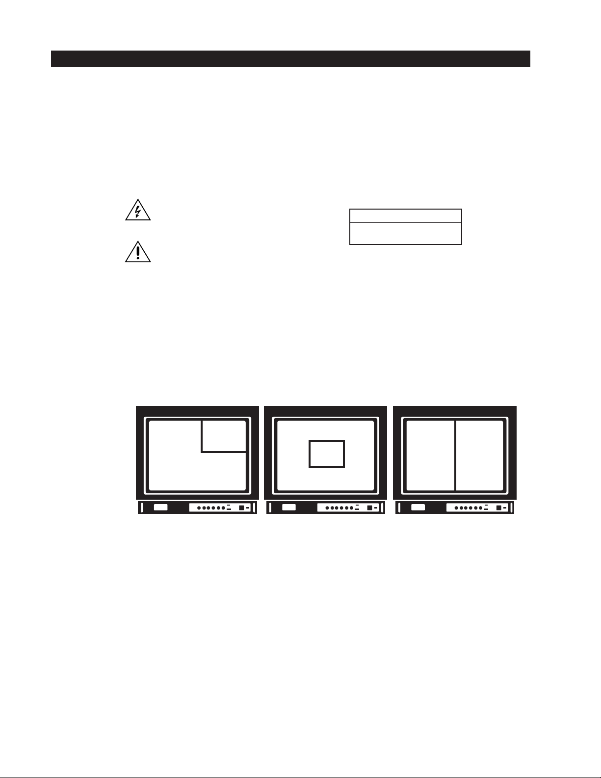
The VSS200DT screen splitter displays video from a single camera or simultaneously displays selected portions of video from
two cameras onto one monitor. This feature also allows both cameras to be recorded onto a single video tape recorder (VCR).
The VSS200DT screen splitter uses high reliability CMOS technology.
CAUTION:
RISK OF ELECTRIC SHOCK.
DO NOT OPEN.
Front panel controls let you adjust the size and position of a second camera’s picture on the monitor. Either camera can be
displayed full screen.
1
CAMERA REQUIREMENTS
• Camera 2 can be black and white only; camera 1 can be color or black and white
•Two externally synchronized cameras
or
One random interlaced camera as a master with one camera having horizontal and vertical drive input as a slave
or
One 2:1 interlaced camera as a master with one camera having horizontal and vertical drive as a slave
2
1
221
Figure 1. Camera 2 Video Positioning Example
OPTIONS
R300 Rack mount kit for up to three units; blank filler panels provided for less than three units
DT200 Dual desktop mount kit; two units can be mounted side-by-side in one desktop chassis
2 C627M-A (8/03)
Page 3
INSTALLATION
VIDEO INPUTS
Each of the two camera inputs is terminated in 75 ohms inside the splitter. So, if you loop a camera video line through a
monitor before routing to the splitter, be sure to set the monitor termination switch to HI-Z.
The camera whose video is routed to the camera 1 input will be the master camera. That is, pictures from the camera 2 input
will be inserted into the pictures from the camera 1 input.
The master camera can be an economical, random interlace type because the splitter can provide horizontal and vertical
synchronization for the second camera. However, a master camera having 2:1 interlace will provide greater synchronization
stability. Refer to the
The second camera either must be independently synchronized to the master camera, or it must be a camera that can accept
horizontal and vertical synchronization from the splitter (refer to Figure 2). Refer to the
Connectors)
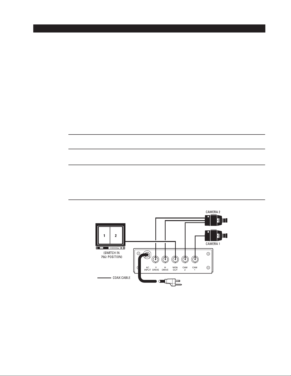
Figure 2 illustrates a typical configuration.
NOTE: (Applies to Figure 2 only.) Camera 2 must be equipped with three BNC connectors (one for VERT drive, one for HORIZ drive,
and one for VIDEO), and hooked to the VSS200DT. Camera 1 only needs to be equipped with one BNC connector for the VIDEO.
If you are using a camera with Gen. Lock, the configuration in Figure 3 applies.
Sync Output (H Drive – V Drive BNC Connectors)
section.
section.
Sync Output (H Drive – V Drive BNC
NOTE: For installations using cameras with Gen. Lock only, the input termination resistor (R1) must be removed to let the
VSS200DT and the camera function properly.
During normal operation CAM 1 is designated as the master camera.
If you want to change CAM 2 to be the master camera, slide the S2 switch on the motherboard in the opposite direction.
Figure 2. VSS200DT Typical Configuration
C627M-A (8/03) 3
Page 4

Figure 3. VSS200DT Configuration for Cameras with Gen. Lock
VIDEO OUTPUT
This output must be terminated with a 75-ohm load. So, if you loop the output through monitors or other accessories, be sure
their terminations are set to HI-Z. Only the last unit on the line should have its termination set to 75 ohms.
SYNC OUTPUT (H DRIVE – V DRIVE BNC CONNECTORS)
When a camera having random interlace is used as the master camera, the second camera must be synchronized by using the
H Drive and V Drive outputs. Refer to Figure 2.
POWER
The supplied five-foot (1.5 m), three-wire line cord with grounded plug complies with safety standards. The unit operates over
a voltage range from 95 to 230 VAC, 50/60 Hz and draws about three watts at 120 VAC.
4 C627M-A (8/03)
Page 5

OPERATION
FRONT PANEL CONTROLS
Figure 4. Front Panel Controls
CAM 1/CAM 2/SPLIT This switch selects camera 1 full screen, camera 2 full screen, or split/insert.
BAL This screwdriver adjustment controls the contrast on camera 2 (the black and white camera).
V SIZE and V POS These screwdriver adjustments control vertical size and position of the split/insert (camera 2 only).
H SIZE and H POS These screwdriver adjustments control horizontal size and position of the split/insert (camera 2 only).
ON/OFF This switch controls power to the unit. The red light indicates the unit is on.
SETUP
1. Turn on the two cameras, the VSS200DT, and the monitor.
2. Set the select switch to CAM 1 (full screen).
3. Adjust camera 1 position and lens until the desired portion of its picture is in the correct position for the composite
display.
4. Set the select switch to CAM 2 (full screen).
5. Adjust camera 2 as in step 3.
6. Set the select switch to SPLIT (split screen).
7. Alternately adjust the insert/split V SIZE/POS (vertical size and position) and H SIZE/POS (horizontal size and position)
screwdriver adjustments until you get the composite picture you want. This moves the camera 2 video only. (You may
have to readjust the position and lens of one or both cameras to get the best composite picture.)
8. Adjust the video contrast of camera 2 (only) using the BAL screwdriver adjustment, if necessary.
C627M-A (8/03) 5
Page 6

SPECIFICATIONS
VIDEO
Inputs: Two
Input Level: 0.5 Vp-p to 2.0 Vp-p
Output Level: Same as input ±0.5 dB
Input/Output Impedance: 75 Ohm
Channel Gain Match: ±0.5 dB
Video Bandwidth: 12 MHz
ELECTRICAL
Input Voltage: 95-135 VAC, 50/60 Hz (230 VAC optional)
Input Power: 3 watts at 120 VAC
Connectors
Video: BNC
H&V Sync: BNC
GENERAL
Temperature Range: -10°F to +140°F (-23°C to +60°C)
Construction: Steel chassis and cover
Finish: Semigloss black enamel with white silk screen
Dimensions: 5.5 (W) x 9.2 (D) x 1.8 (H) inches (14 x 23.5 x 4.6 cm)
Weight: 2 lb (0.5 kg)
Shipping Weight: 4 lb (1.8 kg)
6 C627M-A (8/03)
Page 7

WARRANTY AND RETURN INFORMATION
WARRANTY
Pelco will repair or replace, without charge, any merchandise proved defective in material or
workmanship for a period of one year after the date of shipment. Exceptions to this warranty are
as noted below:
• Five years on Pelco manufactured cameras (CC3500/CC3600/CC3700 and MC3500/
MC3600 Series); two years on all other cameras.
• Three years on Genex® Series (multiplexers, server, and keyboard) and 090 Series
Camclosure® Camera System.
•Two years on 100/150, 200 and 300 Series Camclosure® Camera Systems.
•Two years on all standard motorized or fixed focal length lenses.
•Two years on Legacy®, CM6700/CM6800/CM8500/CM9500/CM9740/CM9760 Matrix, DF5
and DF8 Series Fixed Dome products.
•Two years on Spectra®, Esprit®, and PS20 Scanners, including when used in continuous
motion applications.
•Two years on Esprit and WW5700 series window wiper (excluding wiper blades).
• Eighteen months on DX Series digital video recorders.
• One year (except video heads) on video cassette recorders (VCRs). Video heads will be
covered for a period of six months.
• Six months on all pan and tilts, scanners or preset lenses used in continuous motion
applications (that is, preset scan, tour and auto scan modes).
Pelco will warrant all replacement parts and repairs for 90 days from the date of Pelco
shipment. All goods requiring warranty repair shall be sent freight prepaid to Pelco, Clovis,
California. Repairs made necessary by reason of misuse, alteration, normal wear, or accident
are not covered under this warranty.
Pelco assumes no risk and shall be subject to no liability for damages or loss resulting from the
specific use or application made of the Products. Pelco’s liability for any claim, whether based on
breach of contract, negligence, infringement of any rights of any party or product liability, relating
to the Products shall not exceed the price paid by the Dealer to Pelco for such Products. In no
event will Pelco be liable for any special, incidental or consequential damages (including loss of
use, loss of profit and claims of third parties) however caused, whether by the negligence of
Pelco or otherwise.
The above warranty provides the Dealer with specific legal rights. The Dealer may also have
additional rights, which are subject to variation from state to state.
If a warranty repair is required, the Dealer must contact Pelco at (800) 289-9100 or (559) 292-1981 to
obtain a Repair Authorization number (RA), and provide the following information:
1. Model and serial number
2. Date of shipment, P.O. number, Sales Order number, or Pelco invoice number
3. Details of the defect or problem
If there is a dispute regarding the warranty of a product which does not fall under the warranty conditions
stated above, please include a written explanation with the product when returned.
Method of return shipment shall be the same or equal to the method by which the item was received by
Pelco.
RETURNS
In order to expedite parts returned to the factory for repair or credit, please call the factory at (800) 289-9100
or (559) 292-1981 to obtain an authorization number (CA number if returned for credit, and RA number if
returned for repair).
All merchandise returned for credit may be subject to a 20% restocking and refurbishing charge.
Goods returned for repair or credit should be clearly identified with the assigned CA or RA number and
freight should be prepaid. Ship to the appropriate address below.
If you are located within the continental U.S., Alaska, Hawaii or Puerto Rico:
Service Department
Pelco
3500 Pelco Way
Clovis, CA 93612-5699
If you are located outside the continental U.S., Alaska, Hawaii or Puerto Rico:
Intermediate Consignee Ultimate Consignee
American Overseas Air Freight Pelco
320 Beach Road 3500 Pelco Way
Burlingame, CA 94010 Clovis, CA 93612-5699
USA USA
REVISION HISTORY
Manual # Date Comments
C627M 8/92 Original version.
C627M-A 8/03 Removed a drawing and references to certain cameras. Removed material on cascading. Changed camera requirements to indicate camera 2 must be black and
® Pelco, the Pelco logo, Spectra, Genex, Legacy, Esprit, and Camclosure are registered trademarks of Pelco. © Copyright 2003, Pelco. All rights reserved.
C627M-A (8/03) 7
white only. Added figure illustrating camera 2 positioning. Reformatted the manual.
Page 8

®
World Headquarters
3500 Pelco Way
Clovis, California 93612 USA
USA & Canada
Tel: 800/289-9100
Fax: 800/289-9150
International
Tel: 1-559/292-1981
Fax: 1-559/348-1120
www.pelco.com
ISO9001
Orangeburg, New York Las Vegas, Nevada Eindhoven, The Netherlands Wokingham, United Kingdom Montreal, Canada
 Loading...