

INSTALLATION/OPERATION
VS5004/VS5008
®
Sequential Switcher
C808M-G (4/05)

Contents
Description . . . . . . . . . . . . . . . . . . . . . . . . . . . . . . . . . . . . . . . . . . . . . . . . . . . . . . . . . . . . . . . . . . . . . . . . . . . . . . . . . . . . . . . . . . . . . . . . . . . . . . . . . .3
Models . . . . . . . . . . . . . . . . . . . . . . . . . . . . . . . . . . . . . . . . . . . . . . . . . . . . . . . . . . . . . . . . . . . . . . . . . . . . . . . . . . . . . . . . . . . . . . . . . . . . . . . . .3
Installation . . . . . . . . . . . . . . . . . . . . . . . . . . . . . . . . . . . . . . . . . . . . . . . . . . . . . . . . . . . . . . . . . . . . . . . . . . . . . . . . . . . . . . . . . . . . . . . . . . . . . . . . . .4
Terminated Camera Inputs and One Monitor Output . . . . . . . . . . . . . . . . . . . . . . . . . . . . . . . . . . . . . . . . . . . . . . . . . . . . . . . . . . . . . . . . . . . . .4
Looping Camera Inputs and One Monitor Output . . . . . . . . . . . . . . . . . . . . . . . . . . . . . . . . . . . . . . . . . . . . . . . . . . . . . . . . . . . . . . . . . . . . . . . .7
Terminated Camera Inputs and Two Monitor Outputs . . . . . . . . . . . . . . . . . . . . . . . . . . . . . . . . . . . . . . . . . . . . . . . . . . . . . . . . . . . . . . . . . . . .9
Looping Camera Inputs and Two Monitor Outputs . . . . . . . . . . . . . . . . . . . . . . . . . . . . . . . . . . . . . . . . . . . . . . . . . . . . . . . . . . . . . . . . . . . . . .12
Coaxitron Control . . . . . . . . . . . . . . . . . . . . . . . . . . . . . . . . . . . . . . . . . . . . . . . . . . . . . . . . . . . . . . . . . . . . . . . . . . . . . . . . . . . . . . . . . . . . . . . . 14
Specifications . . . . . . . . . . . . . . . . . . . . . . . . . . . . . . . . . . . . . . . . . . . . . . . . . . . . . . . . . . . . . . . . . . . . . . . . . . . . . . . . . . . . . . . . . . . . . . . . . . . . . . .17
List of Illustrations
1 VS5004 Terminated Camera Inputs - One Monitor . . . . . . . . . . . . . . . . . . . . . . . . . . . . . . . . . . . . . . . . . . . . . . . . . . . . . . . . . . . . . . . . . . . . . . . 4
2 VS5008 Terminated Camera Inputs - One Monitor . . . . . . . . . . . . . . . . . . . . . . . . . . . . . . . . . . . . . . . . . . . . . . . . . . . . . . . . . . . . . . . . . . . . . . . 5
3 VS5004 Alarm Connections . . . . . . . . . . . . . . . . . . . . . . . . . . . . . . . . . . . . . . . . . . . . . . . . . . . . . . . . . . . . . . . . . . . . . . . . . . . . . . . . . . . . . . . . . 5
4 VS5008 Alarm Connections . . . . . . . . . . . . . . . . . . . . . . . . . . . . . . . . . . . . . . . . . . . . . . . . . . . . . . . . . . . . . . . . . . . . . . . . . . . . . . . . . . . . . . . . . 6
5 Looping Conversion Modification . . . . . . . . . . . . . . . . . . . . . . . . . . . . . . . . . . . . . . . . . . . . . . . . . . . . . . . . . . . . . . . . . . . . . . . . . . . . . . . . . . . . . 8
6 VS5004 Looping Camera Inputs - One Monitor . . . . . . . . . . . . . . . . . . . . . . . . . . . . . . . . . . . . . . . . . . . . . . . . . . . . . . . . . . . . . . . . . . . . . . . . . .8
7 VS5008 Looping Camera Inputs - One Monitor . . . . . . . . . . . . . . . . . . . . . . . . . . . . . . . . . . . . . . . . . . . . . . . . . . . . . . . . . . . . . . . . . . . . . . . . . .9
8 VS5004 Conversion For Two-Monitor Operation . . . . . . . . . . . . . . . . . . . . . . . . . . . . . . . . . . . . . . . . . . . . . . . . . . . . . . . . . . . . . . . . . . . . . . . .10
9 VS5004 Terminated Camera Inputs - Two Monitors. . . . . . . . . . . . . . . . . . . . . . . . . . . . . . . . . . . . . . . . . . . . . . . . . . . . . . . . . . . . . . . . . . . . . .11
10 VS5008 Terminated Camera Inputs - Two Monitors. . . . . . . . . . . . . . . . . . . . . . . . . . . . . . . . . . . . . . . . . . . . . . . . . . . . . . . . . . . . . . . . . . . . . .11
11 VS5004 Looping Camera Inputs - Two Monitors . . . . . . . . . . . . . . . . . . . . . . . . . . . . . . . . . . . . . . . . . . . . . . . . . . . . . . . . . . . . . . . . . . . . . . . .13
12 VS5008 Looping Camera Inputs- Two Monitors. . . . . . . . . . . . . . . . . . . . . . . . . . . . . . . . . . . . . . . . . . . . . . . . . . . . . . . . . . . . . . . . . . . . . . . . .13
13 VS5004 with Coaxitron Control . . . . . . . . . . . . . . . . . . . . . . . . . . . . . . . . . . . . . . . . . . . . . . . . . . . . . . . . . . . . . . . . . . . . . . . . . . . . . . . . . . . . .16
14 VS5008 with Coaxitron Control . . . . . . . . . . . . . . . . . . . . . . . . . . . . . . . . . . . . . . . . . . . . . . . . . . . . . . . . . . . . . . . . . . . . . . . . . . . . . . . . . . . . .16
2 C808M-G (4/05)

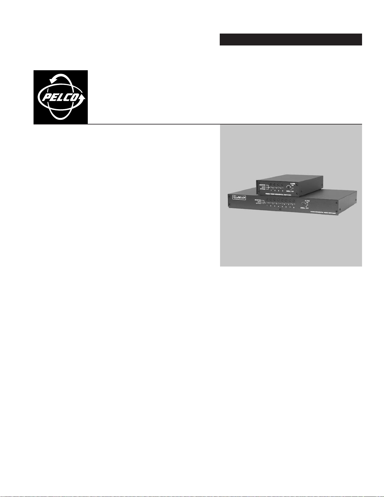
Description
The VS5004 and VS5008 sequential switchers are designed to switch up to four (VS5004) or eight (VS5008) cameras manually or automatically to
one or two monitors with automatic response to alarm inputs. Both versions are Coaxitron
mounted.
MODELS
VS5004 Sequential switcher with four camera inputs and two monitor outputs, 120 VAC
VS5004/220 Same as VS5004 except 230 VAC
VS5008 Sequential switcher with eight camera inputs and two monitor outputs, 120 VAC
VS5008/220 Same as VS5008 except 230 VAC
®
compatible and can be placed on a desktop or rack
C808M-G (4/05) 3
a.
a.
Installation
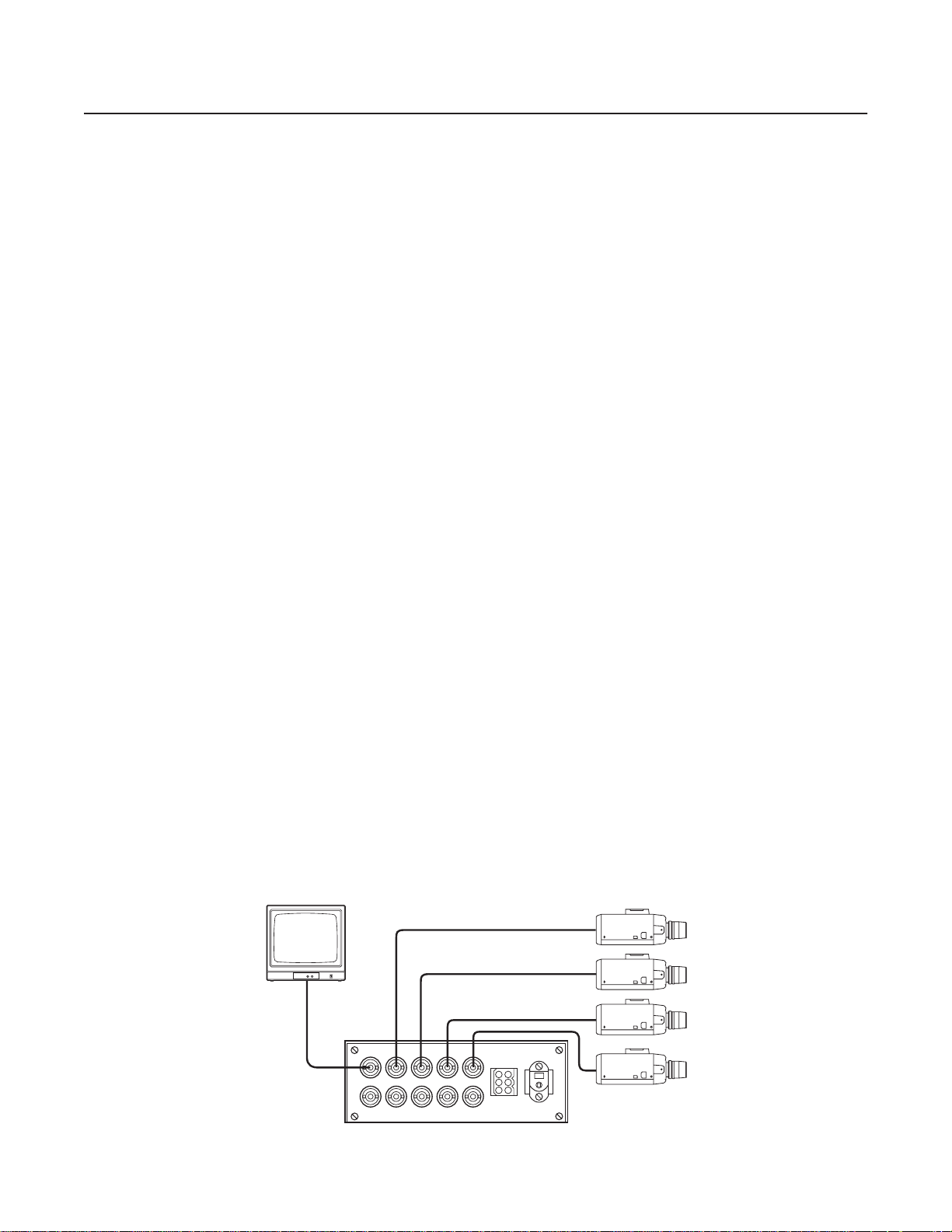
TERMINATED CAMERA INPUTS AND ONE MONITOR OUTPUT
1. Make all equipment connections. Refer to Figure 1 (VS5004) or Figure 2 (VS5008).
VS5008 only: When configured for one-monitor operation, the monitor must be connected to the MON 2 output. The MON 1 output must
be terminated with a 75-ohm BNC terminator.
2. Make alarm connections if required. Refer to Figure 3 (VS5004) or Figure 4 (VS5008) and do the following:
VS5004
Input: Connect the alarm contact between the appropriate input (pins 1-4) and common (pin 5) on the 6-pin connector receptacle.
Pins 1 thru 4 directly correspond with the like-numbered front panel camera switches of the VS5004. The alarm output is an
open-collector NPN transistor. Current from the output to circuit ground should not exceed 600 mA.
b. Output: To activate an external device during an alarm, connect the device at pins 5 and 6 on the 6-pin connector.
VS5008
Input: Connect the alarm contact between the appropriate ALARM INPUT (terminals 1-8) and common (COM) terminal. The alarm
output is an open-collector NPN transistor. Current from the output to circuit ground should not exceed 40 mA.
b. Output: To activate an external device during an alarm, connect the device at the ALARM OUT terminal and the common (COM)
terminal.
3. Set the ALARM switch to the ON position.
NOTES:
• When an alarm occurs, the monitor immediately switches to the alarmed channel, and the associated LED blinks. Multiple alarmed
channels sequence every five seconds (VS5004) or three seconds (VS5008). The alarm has priority over the MONITOR/AUTO/BYPASS
switch settings.
• Once triggered, the alarm remains on until the input condition is removed or the ALARM switch is moved to the OFF position.
• When the ALARM switch is set to the OFF position, all alarm inputs are ignored.
4. For channels with cameras connected to the video inputs, set the front panel switches to the AUTO position. All unconnected video inputs
should have their channel switches set to the BYPASS position.
NOTE: All channels with a switch in the AUTO position will automatically sequence through the monitor. To view one specific channel
continuously, set the corresponding switch to the MONITOR position. To remove a channel from the sequence, set the corresponding switch to
the BYPASS position.
5. Connect the AC adapter to the 12 VAC input plug on the rear of the VS5004 or VS5008. Connect the transformer to a 120 VAC (VS5004 or
VS5008) or 230 VAC (VS5004/220 or VS5008/220) power source. After power up, the switcher will begin sequencing.
6. Using a screwdriver, adjust the DWELL interval control to the desired setting. This control adjusts the interval time from a minimum of
1 second to a maximum of 70 seconds nominal. To increase the interval, turn the control clockwise. To decrease the interval, turn the
control counterclockwise. The DWELL interval control is a precision 15-turn potentiometer. Each complete turn of this control will adjust the
time interval by approximately 4 to 5 seconds.
MON 1
BRIGHT CONTRAST
12 VAC
INPUT
ALARM
4321
MON 1
IN 1 2 3 4
MON 2
OUT 6
COMMON 5
Figure 1. VS5004 Terminated Camera Inputs - One Monitor
4 C808M-G (4/05)
NOTE: MON 1 MUST BE
TERMINATED.
12 VAC
INPUT
ALARM
INPUT
12345678
COM
87654321
ALARM OUT
CAMERAS
VS5008 (REAR)
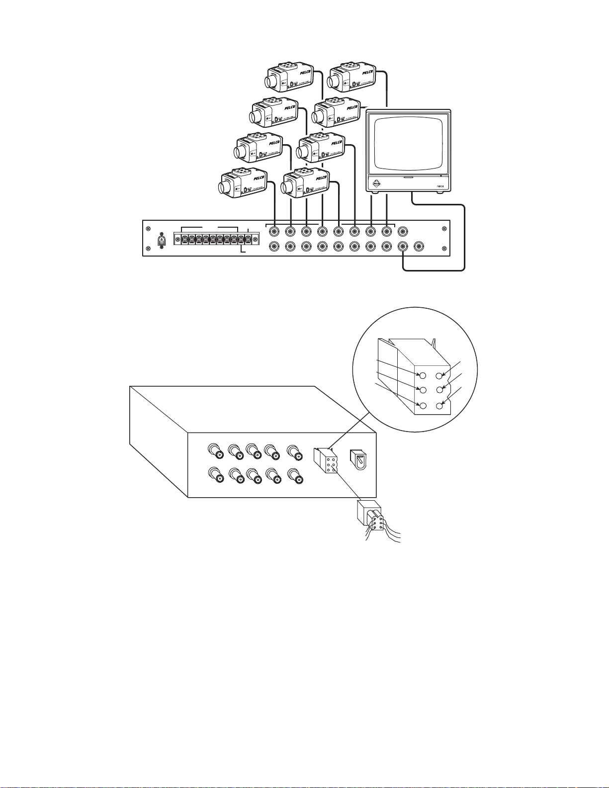
Figure 2. VS5008 Terminated Camera Inputs - One Monitor
REAR VIEW
MON 1
MON 2
CAMERAS
3
4
12
1234
ALARM
IN 1 2 3 4
OUT 6 -- TO VCR
COMMON 5
YEL
GRN
BLK
12VAC
INPUT
MON 1
MON 2 MON X
6-PIN CONNECTOR
RECEPTACLE
4
5
6
BRN
1
RD
2
OR
3
TO EXTERNAL
ALARM CIRCUITRY
Figure 3. VS5004 Alarm Connections
C808M-G (4/05) 5
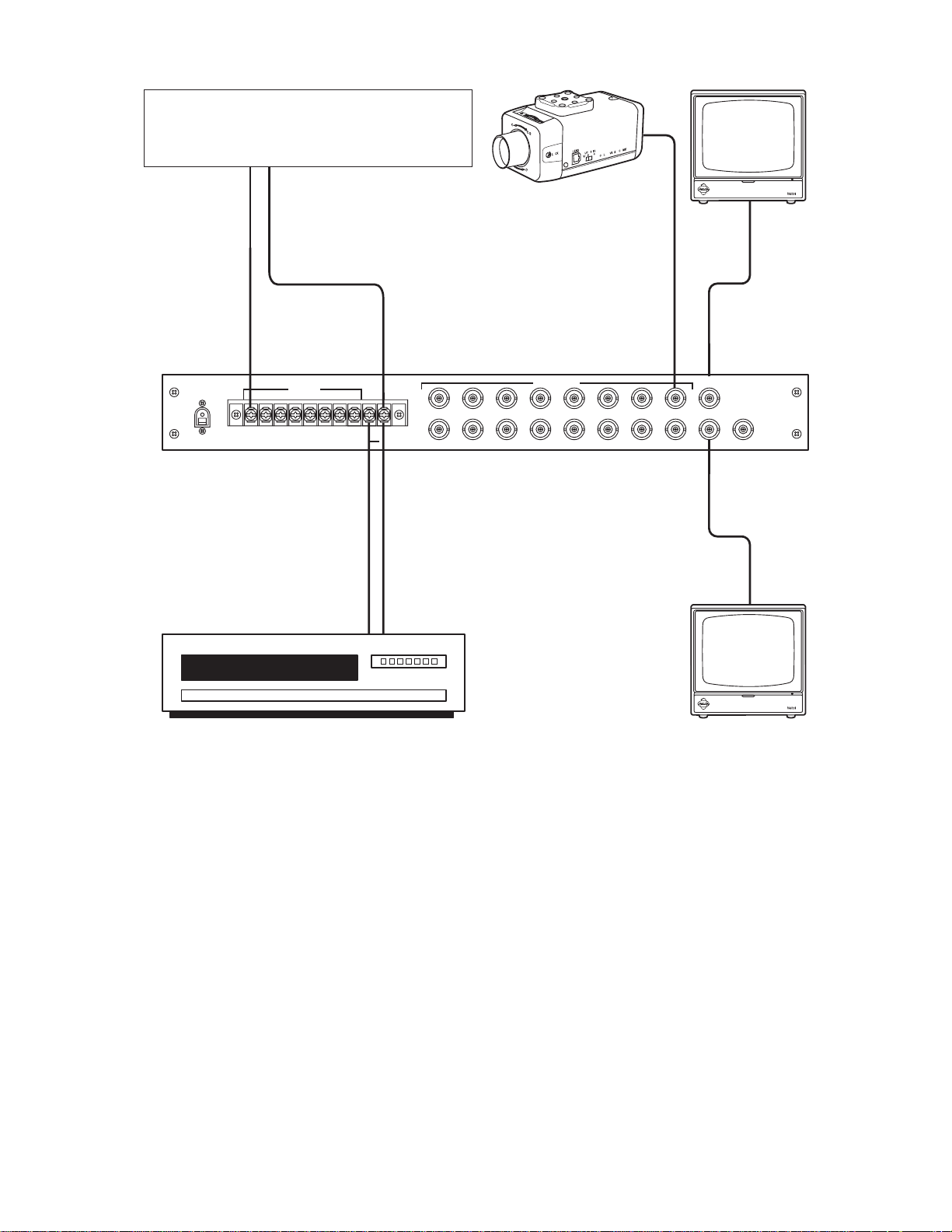
UP TO EIGHT ALARM INPUTS (ALARM INPUT FROM
MOTION DETECTOR, DOOR CONTACT, ETC., THROUGH
NORMALLY OPEN SWITCH). EACH ALARM DEVICE MUST BE
CONNECTED TO THE "COM" TERMINAL.
UP TO EIGHT VIDEO INPUTS
VCR
12 VAC
INPUT
ALARM
INPUT
12345678
COM
87654321
ALARM OUT
CAMERAS
VS5008 (REAR)
OPEN COLLECTOR OUTPUT FOR
VCR ACTIVATION IN ALARM
CONDITION. ONLY ONE VCR
CAN BE USED IN THIS
CONFIGURATION.
Figure 4. VS5008 Alarm Connections
MON 1
MON 2 MON X
6 C808M-G (4/05)

a.
a.
•
•
•
LOOPING CAMERA INPUTS AND ONE MONITOR OUTPUT
1. Convert the switcher to looping operation. Refer to Figure 5 and do the following:
NOTE: Looping and terminated inputs may be mixed.
a. Remove the cover.
b. Remove the rear panel of the chassis.
c. Locate the 75-ohm resistors located on the inside of the rear panel BNC jacks.
d. For each input to be looped, use wire cutters to clip one of the attached resistor leads.
e. Replace the cover.
2. Make all equipment connections. Refer to Figure 6 (VS5004) or Figure 7 (VS5008).
VS5008 only: When configured for one-monitor operation, the monitor must be connected to the MON 2 output. The MON 1 output must
be terminated with a 75-ohm BNC terminator.
3. Make alarm connections if required. Refer to Figure 3 (VS5004) or Figure 4 (VS5008) and do the following:
VS5004
Input: Connect the alarm contact between the appropriate input (pins 1-4) and common (pin 5) on the 6-pin connector receptacle.
Pins 1 thru 4 correspond directly with the like-numbered front panel camera switches of the VS5004. The alarm output is an
open-collector NPN transistor. Current from the output to circuit ground should not exceed 600 mA.
b. Output: To activate an external device during an alarm, connect the device at pins 5 and 6 on the 6-pin connector.
VS5008
Input: Connect the alarm contact between the appropriate ALARM INPUT (terminals 1-8) and common (COM) terminal. The alarm
output is an open-collector NPN transistor. Current from the output to circuit ground should not exceed 40 mA.
b. Output: To activate an external device during an alarm, connect the device at the ALARM OUT terminal and the common (COM)
terminal.
4. Set the ALARM switch to the ON position.
NOTES:
When an alarm occurs, the monitor immediately switches to the alarmed channel, and the associated LED blinks. Multiple alarmed
channels sequence every five seconds (VS5004) or three seconds (VS5008). The alarm has priority over the MONITOR/AUTO/BYPASS
switch settings.
Once triggered, the alarm remains on until the input condition is removed or the ALARM switch is moved to the OFF position.
When in the ALARM switch is set to the OFF position, all alarm inputs are ignored.
5. For channels with cameras connected to the video inputs, set the front panel switches to the AUTO position. All unconnected video inputs
should have their channel switch set to the BYPASS position.
NOTE: All channels with a switch in the AUTO position will automatically sequence through the monitor. To view one specific channel
continuously, set the corresponding switch to the MONITOR position. To remove a channel from the sequence, set the corresponding switch to
the BYPASS position.
6. Connect the AC adapter to the 12 VAC input plug on the rear of the VS5004 or VS5008. Connect the transformer to a 120 VAC (VS5004 or
VS5008) or 230 VAC (VS5004/220 or VS5008/220) power source. After power up, the switcher will begin sequencing.
7. Using a screwdriver, adjust the DWELL interval control to the desired setting. This control adjusts the interval time from a minimum of
1 second to a maximum of 70 seconds nominal. To increase the interval, turn the control clockwise. To decrease the interval, turn the
control counterclockwise. The DWELL interval control is a precision 15-turn potentiometer. Each complete turn of this control will adjust the
time interval by approximately 4 to 5 seconds.
C808M-G (4/05) 7

CLIP HERE
FOR EACH
CHANNEL
MON 1
BRIGHT CONTRAST
75-OHM RESISTOR
REAR PANEL (SWITCHER)
Figure 5. Looping Conversion Modification
BNC CONNECTOR
12 VAC
INPUT
ALARM
4321
MON 1
IN 1 2 3 4
MON 2
ADDITIONAL EQUIPMENT
VIDEO INPUTS
TERMINATED
OUT 6
COMMON 5
Figure 6. VS5004 Looping Camera Inputs - One Monitor
8 C808M-G (4/05)

NOTE: IN THIS CONFIGURATION,
MON 1 MUST BE TERMINATED
AND THE UNIT MUST BE MODIFIED
TO BE LOOPING (REFER TO FIGURE 5).
a.
a.
12 VAC
INPUT
ALARM
INPUT
12345678
COM
ALARM OUT
CAMERAS
87654321
MON 1
MON 2 MON X
VS5008 (REAR)
VIDEO INPUTS
ADDITIONAL EQUIPMENT
TERMINATED
Figure 7. VS5008 Looping Camera Inputs - One Monitor
TERMINATED CAMERA INPUTS AND TWO MONITOR OUTPUTS
1. Convert the VS5004 to dual-monitor operation. Refer to Figure 8 and do the following:
a. Remove the cover.
b. Remove the rear panel of the chassis.
c. Remove the four screws attaching the PC board to the chassis.
d. Pull the PC board and rear panel assembly out of the chassis.
e. Turn the PC board over and rewire.
f. Replace the PC board, rear panel assembly, and cover.
2. Make all equipment connections. Refer to Figure 9 (VS5004) or Figure 10 (VS5008).
VS5004 only: In this configuration, MON 1 must be terminated with a 75-ohm terminator and MON 2 must be terminated in the HI Z position.
3. Make alarm connections if required. Refer to Figure 3 (VS5004) or Figure 4 (VS5008) and do the following:
VS5004
Input: Connect the alarm contact between the appropriate input (pins 1-4) and common (pin 5) on the 6-pin connector receptacle.
Pins 1 thru 4 correspond directly with the like-numbered front panel camera switches of the VS5004. The alarm output is an
open-collector NPN transistor. Current from the output to circuit ground should not exceed 600 mA.
b. Output: To activate an external device during an alarm, connect the device at pins 5 and 6 on the 6-pin connector.
VS5008
Input: Connect the alarm contact between the appropriate ALARM INPUT (terminals 1-8) and common (COM) terminal. The alarm
output is an open-collector NPN transistor. Current from the output to circuit ground should not exceed 40 mA.
b. Output: To activate an external device during an alarm, connect the device at the ALARM OUT terminal and the common (COM)
terminal.
C808M-G (4/05) 9

•
•
•
•
•
•
•
•
4. Set the ALARM switch to the ON position.
NOTES:
With all channel switches set to the AUTO position, both monitors immediately switch to the alarmed channel and the associated LED
blinks. Multiple alarmed channels sequence every five seconds (VS5004) or three seconds (VS5008). The alarm has priority over the
MONITOR/AUTO/BYPASS switch settings.
If a channel switch is set to the MONITOR position, Monitor 1 switches to the alarmed channel while Monitor 2 displays the selected
(MONITOR) channel.
If a channel switch is set to the BYPASS position, Monitor 1 switches to that channel if it is alarmed.
Once triggered, the alarm remains on until the input condition is removed or the ALARM switch is moved to the OFF position.
When in the ALARM switch is set to the OFF position, all alarm inputs are ignored.
5. For channels with cameras connected to the video inputs, set the front panel switches to the AUTO position. All unconnected video inputs
should have their channel switch set to the BYPASS position.
NOTES:
With all channel switches in the AUTO position, both monitors sequence simultaneously.
Monitor 2 can be manually switched to any channel for continuous viewing by setting the desired channel’s switch to the MONITOR
position. If multiple channels are set to MONITOR, only the lowest numbered channel will be displayed. This does not affect the
sequencing for Monitor 1.
To remove a channel from the sequence, set the corresponding switch to the BYPASS position.
6. Connect the AC adapter to the 12 VAC input plug on the rear of the VS5004 or VS5008. Connect the transformer to a 120 VAC (VS5004 or
VS5008) or 230 VAC (VS5004/220 or VS5008/220) power source. After power up, the switcher will begin sequencing.
7. Using a screwdriver, adjust the DWELL interval control to the desired setting. This control adjusts the interval time from a minimum of
1 second to a maximum of 70 seconds nominal. To increase the interval, turn the control clockwise. To decrease the interval, turn the
control counterclockwise. The DWELL interval control is a precision 15-turn potentiometer. Each complete turn of this control will adjust the
time interval by approximately 4 to 5 seconds.
MON 1 MON 2
PCB 90000101 COMPONENT SIDE
X5 H5
J1 1
G
BLU
X4
H6
H3
X3
H2
X2
H1
X1
X6
GRN
W/RED
RED
ORG
B5
MON1
BRN
B4 V4
B3 V3 VG
B2 V2
B1 V1
1
J2
456
123
TO CONVERT PC BOARD TO TWO MONITOR OPERATION,
REROUTE THE JUMPER WIRES AS FOLLOWS.
WIRE COLOR
BROWN
RED
ORANGE
YELLOW
GREEN
BLUE
WHITE/RED
REMOVE WIRE
FROM PIN
H1
H2
H3
H4
H5
X6
G
CONNECT WIRE
TO PIN
B1
B2
B3
B4
B5
H5
X6
Figure 8. VS5004 Conversion For Two-Monitor Operation
10 C808M-G (4/05)

MON 2
MON 1
BRIGHT CONTRASTBRIGHT CONTRAST
4321
MON 1
MON 2
ALARM
IN 1 2 3 4
OUT 6
COMMON 5
12 VAC
INPUT
NOTE: IN THIS CONFIGURATION, MON 1 MUST BE TERMINATED WITH A 75-OHM TERMINATOR
AND MON 2 MUST BE IN THE “HI Z” POSITION.
Figure 9. VS5004 Terminated Camera Inputs - Two Monitors
12 VAC
INPUT
ALARM
INPUT
12345678
COM
87654321
ALARM OUT
CAMERAS
MON 1
MON 2 MON X
VS5008 (REAR)
Figure 10. VS5008 Terminated Camera Inputs - Two Monitors
C808M-G (4/05) 11

a.
a.
•
LOOPING CAMERA INPUTS AND TWO MONITOR OUTPUTS
1. Convert the VS5004 to dual-monitor operation. Refer to Figure 8 and do the following:
a. Remove the cover.
b. Remove the rear panel of the chassis.
c. Remove the four screws attaching the PC board to the chassis.
d. Pull the PC board and rear panel assembly out of the chassis.
e. Turn the PC board over and rewire.
2. Convert to looping operation. Refer to Figure 5 and do the following:
NOTE: Looping and terminated inputs may be mixed.
a. Locate the 75-ohm resistors located on the inside of the rear panel BNC jacks.
b. For each input to be looped, use wire cutters to clip one of the attached resistor leads.
c. Replace the cover.
3. Make all equipment connections. Refer to Figure 11 (VS5004) or Figure 12 (VS5008).
(VS5004 only) In this configuration, MON 1 must be terminated with a 75-ohm terminator and MON 2 must be terminated in the
HI Z position.
•
•
•
•
•
•
•
4. Make alarm connections if required. Refer to Figure 3 (VS5004) or Figure 4 (VS5008) and do the following:
VS5004
Input: Connect the alarm contact between the appropriate input (pins 1-4) and common (pin 5) on the 6-pin connector receptacle.
Pins 1 thru 4 correspond directly with the like-numbered front panel camera switches of the VS5004. The alarm output is an
open-collector NPN transistor. Current from the output to circuit ground should not exceed 600 mA.
b. Output: To activate an external device during an alarm, connect the device at pins 5 and 6 on the 6-pin connector.
VS5008
Input: Connect the alarm contact between the appropriate ALARM INPUT (terminals 1-8) and common (COM) terminal. The alarm
output is an open-collector NPN transistor. Current from the output to circuit ground should not exceed 40 mA.
b. Output: To activate an external device during an alarm, connect at the ALARM OUT terminal and the common (COM) terminal.
5. Set the ALARM switch to the ON position.
NOTES:
With all channel switches set to the AUTO position, both monitors immediately switch to the alarmed channel and the associated LED
blinks. Multiple alarmed channels sequence every five seconds (VS5004) or three seconds (VS5008). The alarm has priority over the
MONITOR/AUTO/BYPASS switch settings.
If a channel switch is set to the MONITOR position, Monitor 1 switches to the alarmed channel while Monitor 2 displays the selected
(MONITOR) channel.
If a channel switch is set to the BYPASS position, Monitor 1 switches to that channel if alarmed.
Once triggered, the alarm remains on until the input condition is removed or the ALARM switch is moved to the OFF position.
When in the ALARM switch is set to the OFF position, all alarm inputs are ignored.
6. For channels with cameras connected to the video inputs, set the front panel switches to the AUTO (center) position. All unconnected video
inputs should have their channel switch set to the BYPASS (down) position.
NOTES:
With all channel switches in the AUTO position, both monitors sequence simultaneously.
Monitor 2 can be manually switched to any channel for continuous viewing by setting the desired channel’s switch to the MONITOR
position. If multiple channels are set to MONITOR, only the lowest numbered channel will be displayed. This does not affect the
sequencing for Monitor 1.
To remove a channel from the sequence, set the corresponding switch to the BYPASS position.
12 C808M-G (4/05)

7. Connect the AC adapter to the 12 VAC input plug on the rear of the VS5004 or VS5008. Connect the transformer to a 120 VAC (VS5004 or
VS5008) or 230 VAC (VS5004/220 or VS5008/220) power source. After power up, the switcher will begin sequencing.
8. Using a screwdriver, adjust the DWELL interval control to the desired setting. This control adjusts the interval time from a minimum of
1 second to a maximum of 70 seconds nominal. To increase the interval, turn the control clockwise. To decrease the interval, turn the
control counterclockwise. The DWELL interval control is a precision 15-turn potentiometer. Each complete turn of this control will adjust the
time interval by approximately 4 to 5 seconds.
MON 2
MON 1
BRIGHT CONTRASTBRIGHT CONTRAST
4321
MON 1
MON 2
VIDEO INPUTS
ADDITIONAL EQUIPMENT
TERMINATED
ALARM
IN 1 2 3 4
OUT 6
COMMON 5
12 VAC
INPUT
NOTE: MON 1 MUST BE TERMINATED WITH A 75-OHM TERMINATOR AND MON 2 MUST BE IN
THE “HI Z” POSITION.
Figure 11. VS5004 Looping Camera Inputs - Two Monitors
NOTE: In this configuration
the unit must be modified in
order to be looping (refer to figure 5).
12 VAC
INPUT
ALARM
INPUT
12345678
COM
87654321
ALARM OUT
CAMERAS
MON 1
MON 2 MON X
VS5008 (REAR)
VIDEO INPUTS
ADDITIONAL EQUIPMENT
TERMINATED
Figure 12. VS5008 Looping Camera Inputs- Two Monitors
C808M-G (4/05) 13

COAXITRON CONTROL
To convert for use with a Coaxitron transmitter, do the following:
1. Convert the VS5004 to dual-monitor operation. Refer to Figure 8 and do the following:
a. Remove the cover.
b. Remove the rear panel of the chassis.
c. Remove the four screws attaching the PC board to the chassis.
d. Pull the PC board and rear panel assembly out of the chassis.
e. Turn the PC board over and rewire.
2. Convert to looping operation. Refer to Figure 5 and do the following:
NOTE: Looping and terminated inputs may be mixed.
a. Locate the 75-ohm resistors located on the inside of the rear panel BNC jacks.
b. For each input to be looped, use wire cutters to clip one of the attached resistor leads.
c. Replace the cover.
3. Make all equipment connections. Refer to Figure 13 (VS5004) or Figure 14 (VS5008).
•
•
•
a.
•
•
•
VS5004
The Coaxitron transmitter must be passive (nonamplified).
To operate a camera via Coaxitron signals, the corresponding channel switch must be in the MONITOR position.
VS5008
The Coaxitron transmitter must be active (amplified).
4. Make alarm connections if required. Refer to Figure 3 (VS5004) or Figure 4 (VS5008) and do the following:
VS5004
Input: Connect the alarm contact between the appropriate input (pins 1-4) and common (pin 5) on the 6-pin connector receptacle.
Pins 1 thru 4 correspond directly with the like-numbered front panel camera switches of the VS5004. The alarm output is an
open-collector NPN transistor. Current from the output to circuit ground should not exceed 600 mA.
b. Output: To activate an external device during an alarm, connect the device at pins 5 and 6 on the 6-pin connector.
VS5008
a. Input: Connect the alarm contact between the appropriate ALARM INPUT (terminals 1-8) and common (COM) terminal. The alarm
output is an open-collector NPN transistor. Current from the output to circuit ground should not exceed 40 mA.
b. Output: To activate an external device during an alarm, connect the device at the ALARM OUT terminal and the common (COM)
terminal.
5. Set the ALARM switch to the ON position.
NOTES:
When an alarm occurs, the monitor immediately switches to the alarmed channel, and the associated LED blinks. Multiple alarmed
channels sequence every five seconds (VS5004) or three seconds (VS5008). The alarm has priority over the MONITOR/AUTO/BYPASS
switch settings.
VS5008 with two-monitor configuration:
– If a channel switch is set to the MONITOR position, Monitor 1 switches to the alarmed channel while Monitor 2 displays the selected
(MONITOR) channel.
– If a channel switch is set to the BYPASS position, Monitor 1 switches to that channel if alarmed.
Once triggered, the alarm remains on until the input condition is removed or the ALARM switch is moved to the OFF position.
When in the ALARM switch is set to the OFF position, all alarm inputs are ignored.
14 C808M-G (4/05)

•
•
6. For channels with cameras connected to the video inputs, set the front panel switches to the AUTO position. All unconnected video inputs
should have their channel switch set to the BYPASS position.
NOTES:
VS5004 and VS5008 with one-monitor configuration: All channels with a switch set in the AUTO position will automatically sequence
through the monitor. To view one specific channel continuously, set the corresponding switch to the MONITOR position. To remove a
channel from the sequence, set the corresponding switch to the BYPASS position.
VS5008 with two-monitor configuration:
– With all channel switches in the AUTO position, both monitors sequence simultaneously.
– Monitor 2 can be manually switched to any channel for continuous viewing by setting the desired channel’s switch to the MONITOR
position. If multiple channels are set to MONITOR, only the lowest numbered channel will be displayed. This does not affect the
sequencing for Monitor 1.
– To remove a channel from the sequence, set the corresponding switch to the BYPASS position.
7. Connect the AC adapter to the 12 VAC input plug on the rear of the VS5004 or VS5008. Connect the transformer to a 120 VAC (VS5004 or
VS5008) or 230 VAC (VS5004/220 or VS5008/220) power source. After power up, the switcher will begin sequencing.
8. Using a screwdriver, adjust the DWELL interval control to the desired setting. This control adjusts the interval time from a minimum of
1 second to a maximum of 70 seconds nominal. To increase the interval, turn the control clockwise. To decrease the interval, turn the
control counterclockwise. The DWELL interval control is a precision 15-turn potentiometer. Each complete turn of this control will adjust the
time interval by approximately 4 to 5 seconds.
C808M-G (4/05) 15

MON 1
BRIGHT CONTRAST
TO FIXED CAMERAS OR
ADDITIONAL RECEIVERS
ALARM
4321
MON 1
IN 1 2 3 4
MON 2
OUT 6
COMMON 5
VS5004 (REAR)
COAXITRON® TRANSMITTER
(REAR)
Figure 13. VS5004 with Coaxitron Control
12 VAC
INPUT
LOOPING
OUTPUT
COAXITRON®
RECEIVER
INPUT FROM
OUTPUT FROM
RECEIVER
MONITOR
J6J7J8
COAXITRON
RECEIVER
12 VAC
12345678
INPUT
UP TO EIGHT RECEIVERS
ALARM
INPUT
COM
87654321
ALARM OUT
VS5008 (REAR)
COAXITRON TRANSMITTER
(REAR)
CAMERAS
LOOPING
OUTPUT
J8
INPUT FROM
RECEIVER
J7
MON 1
MON 2 MON X
OUTPUT TO
MONITOR
J6
NOTE: IN THIS CONFIGURATION, THE LOOPING OUTPUT (J8) IS UNTERMINATED.
Figure 14. VS5008 with Coaxitron Control
16 C808M-G (4/05)

Specifications
VIDEO
Inputs Terminating (75 ohms) or looping
Outputs
Monitor 1 75 ohms
Monitor 2
VS5004 Hi Z
VS5008 75 ohms
Monitor X
VS5008 Coaxitron transmitter (nonamplified) output
Gain Unity
Dwell Adjustable from 1-70 seconds nominal
Frequency
Response Flat within +/-1 dB to 10 MHz
Maximum
Signal Level 2 Vp-p
Tilt Less than 2%
Crosstalk Better than -40 dB at 5.5 MHz
ELECTRICAL
Power Requirements
for Transformer 1.5 VA (0.125 A) at 12 volts RMS +/-15%, 50/60 Hz from a dedicated, isolated 120 or 230 VAC power
source. Wall transformer is provided with unit
NOTE: These units are also capable of operating on 12 VDC for mobile applications.
Connectors BNC
Alarm In Normally open relay contact, 10 V at 1 mA
Alarm Out Open collector
GENERAL
Construction
Chassis Steel, zinc plated
Cover Steel, black polyester powder coat
Panel Aluminum, black polyester powder coat with white silk screen
Environment 32
Dimensions
VS5004 1.75" H x 5.63" W x 8.75" D inches (4.45 x 14.30 x 22.23 cm)
VS5008 1.75" H x 14.50" W x 8.50" D inches (4.45 x 36.83 x 21.59 cm)
Weight
VS5004 2.5 lb (1.13 kg)
VS5008 7 lb (3.17 kg)
Rating Meets Nema Type 1 standards
°
to 120
°
F (0
° to 49°C)
C808M-G (4/05) 17

18 C808M-G (4/05)

PRODUCT WARRANTY AND RETURN INFORMATION
WARRANTY
Pelco will repair or replace, without charge, any merchandise proved defective in material or
workmanship for a period of one year after the date of shipment.
Exceptions to this warranty are as noted below:
• Five years on FT/FR8000 Series fiber optic products.
®
• Three years on Genex
• Three years on Camclosure® and fixed camera models, except the CC3701H-2,
CC3701H-2X, CC3751H-2, CC3651H-2X, MC3651H-2, and CC3651H-2X camera models,
which have a five-year warranty.
•Two years on standard motorized or fixed focal length lenses.
•Two years on Legacy
fixed dome products.
•Two years on Spectra
continuous motion applications.
•Two years on Esprit
• Eighteen months on DX Series digital video recorders, NVR300 Series network video
recorders, and Endura
• One year (except video heads) on video cassette recorders (VCRs). Video heads will be
covered for a period of six months.
• Six months on all pan and tilts, scanners or preset lenses used in continuous motion
applications (that is, preset scan, tour and auto scan modes).
Pelco will warrant all replacement parts and repairs for 90 days from the date of Pelco
shipment. All goods requiring warranty repair shall be sent freight prepaid to Pelco, Clovis,
California. Repairs made necessary by reason of misuse, alteration, normal wear, or accident
are not covered under this warranty.
Pelco assumes no risk and shall be subject to no liability for damages or loss resulting from
the specific use or application made of the Products. Pelco’s liability for any claim, whether
based on breach of contract, negligence, infringement of any rights of any party or product
liability, relating to the Products shall not exceed the price paid by the Dealer to Pelco for
such Products. In no event will Pelco be liable for any special, incidental or consequential
damages (including loss of use, loss of profit and claims of third parties) however caused,
whether by the negligence of Pelco or otherwise.
The above warranty provides the Dealer with specific legal rights. The Dealer may also have
additional rights, which are subject to variation from state to state.
Series products (multiplexers, server, and keyboard).
®
, CM6700/CM6800/CM9700 Series matrix, and DF5/DF8 Series
®
, Esprit®, ExSite™, and PS20 Scanners, including when used in
®
and WW5700 Series window wiper (excluding wiper blades).
™
Series distributed network-based video products.
If a warranty repair is required, the Dealer must contact Pelco at (800) 289-9100 or
(559) 292-1981 to obtain a Repair Authorization number (RA), and provide the following
information:
1. Model and serial number
2. Date of shipment, P.O. number, Sales Order number, or Pelco invoice number
3. Details of the defect or problem
If there is a dispute regarding the warranty of a product which does not fall under the
warranty conditions stated above, please include a written explanation with the product
when returned.
Method of return shipment shall be the same or equal to the method by which the item was
received by Pelco.
RETURNS
In order to expedite parts returned to the factory for repair or credit, please call the factory at
(800) 289-9100 or (559) 292-1981 to obtain an authorization number (CA number if returned
for credit, and RA number if returned for repair).
All merchandise returned for credit may be subject to a 20% restocking and refurbishing
charge.
Goods returned for repair or credit should be clearly identified with the assigned CA or RA
number and freight should be prepaid. Ship to the appropriate address below.
If you are located within the continental U.S., Alaska, Hawaii or Puerto Rico, send goods to:
Service Department
Pelco
3500 Pelco Way
Clovis, CA 93612-5699
If you are located outside the continental U.S., Alaska, Hawaii or Puerto Rico and are
instructed to return goods to the USA, you may do one of the following:
If the goods are to be sent by a COURIER SERVICE, send the goods to:
Pelco
3500 Pelco Way
Clovis, CA 93612-5699 USA
If the goods are to be sent by a FREIGHT FORWARDER, send the goods to:
Pelco c/o Expeditors
473 Eccles Avenue
South San Francisco, CA 94080 USA
Phone: 650-737-1700
Fax: 650-737-0933
REVISION HISTORY
Manual # Date Comments
C808M 7/87 Original version.
C808M-A 2/91 Updated format. Specification section rewritten. Rack-mount instruction section dropped.
C808M-B 4/90 Incorporated addendum for dwell instructions.
C808M-C 9/92 Optional accessories updated. Changes to dwell adjustment procedure.
C808M-D 4/95 Added new Figure 5 drawing. Erroneous information on alarm operation (bridging) was deleted (ECO 94-222). Dwell internal timing changed from “3 to 70” to “1 to
C808M-E 6/98 Changed wiring color from blue to black in Figure 5. Changed manual format.
C808M-F 12/99 Added information on use with Coaxitron transmitter. Changed to new manual format.
C808M-G 4/05 Added VS5008 information from manual C809M-E.
Pelco, the Pelco logo, Spectra, Genex, Esprit, Camclosure, and Legacy are registered trademarks of Pelco. © Copyright 2005, Pelco. All rights reserved.
70” seconds (ECO 93-062). Specifications updated. Two-column format.

Worldwide Headquarters
3500 Pelco Way
Clovis, California 93612 USA
USA & Canada
Tel: 800/289-9100
Fax: 800/289-9150
International
Tel: 1-559/292-1981
Fax: 1-559/348-1120
www.pelco.com
ISO9001
United States | Canada | United Kingdom | The Netherlands | Singapore | Spain | Scandinavia | France | Middle East
 Loading...