

Page 1
ADDENDUM
Addendum No. C1563M
Date February 19, 2008
Manual Affected VMX300 Video Management System Installation Manual, C1552M-C
Several components on the rear panel of the VMX300/VMX300-E workstations have been moved to new positions and the illustrations in the VMX300(-E)
Installation manual (C1552M-C) are out-of-date. Please refer to the information and illustrations in this addendum when using the following rear panel
connectors:
• Monitor outputs
• Video inputs
• COM 3 and COM 4 (RS-422 ports)
• USB ports
Rear View
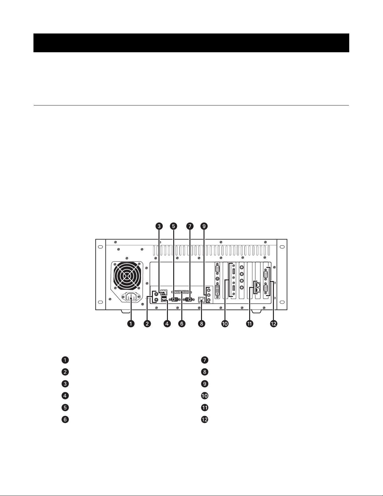
In Figure 1, the rear panel of the VMX300-SYS-4/VMX300-E-SYS-4 workstation is used to identify the components that are common to all models. Monitor
output ports and video input ports are identified for each workstation model in VMX300(-E) Monitor Outputs and VMX300(-E) Analog Video Inputs, beginning
on page 2.
Figure 1. VMX300(-E) Rear View
Power COM 2 (RS-232)*
Mouse and Keyboard Ports (PS/2) Primary Ethernet Port (gigabit rate)
Secondary Ethernet Port (megabit rate) Audio Ports
USB Ports* USB Ports*
COM 1 (RS-232)* Modem Ports (reserved for future use)
Parallel Port (refer to the Windows
printer installation instructions)
*A USB port expander can be used to increase the total number of USB ports and serial communication ports (RS-232).
®
documentation for
COM 3 and COM 4 (RS-422)
Page 2
VMX300(-E) MONITOR OUTPUTS
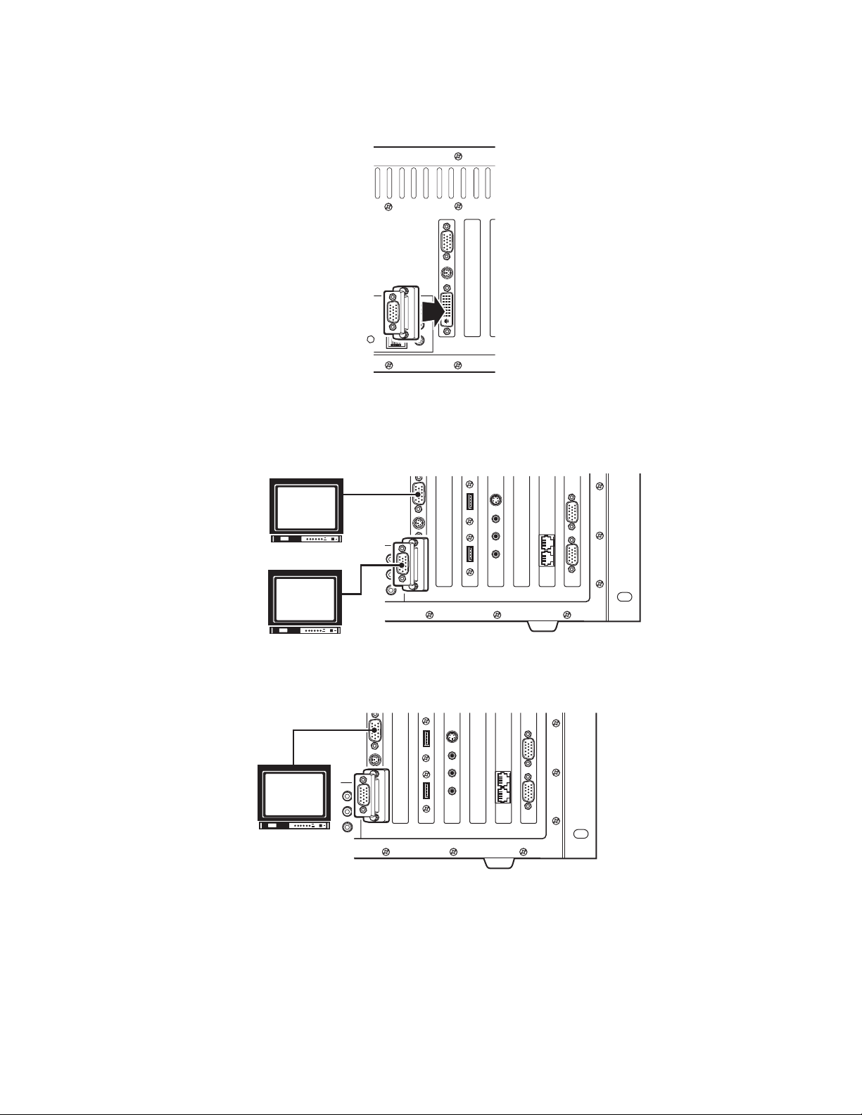
1. Connect the VGA adapter to the digital video interface (DVI) connector on the rear panel.
Figure 2. Monitor Port Adapter Connection
2. Use the monitor cables provided with your monitors (not supplied) to connect monitors to the workstation as follows:
• Dual-monitor systems: Connect the left monitor to the bottom input and the right monitor to the top input (refer to Figure 3).
RIGHT VGA
MONITOR
LEFT VGA
MONITOR
Figure 3. How to Connect Monitors to a VMX300(-E) Workstation
• Single-monitor systems: If you are using just one monitor, use the top monitor input only (refer to Figure 4).
Figure 4. How to Connect a Single Monitor to a VMX300(-E) Workstation
2 C1563M (2/08)
Page 3
VMX300(-E) ANALOG VIDEO INPUTS
You can connect one analog video input to -1 model workstations, and up to four analog video inputs to -4 model workstations.
Analog video sources include the following:
• A video source (such as a camera, VCR, or multiplexer) connected directly to the VMX300(-E) workstation rear panel
• Video output from a matrix switcher, using a cable connection from one of the matrix switcher monitor outputs to the VMX300(-E) workstation rear
panel
NOTE: Refer to the appropriate installation manual for each video input device for additional connection instructions.
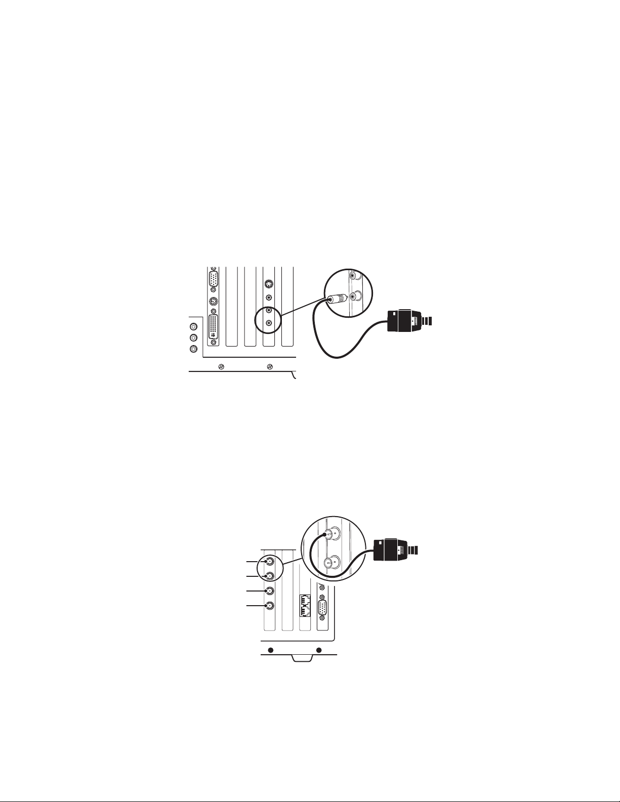
-1 MODEL WORKSTATIONS
1. Connect the RCA-to-BNC video input adapter to the video port on the rear panel.
2. Using a BNC video cable (not supplied), connect the video source to the input adapter.
When you configure settings in the server software for this workstation, add a custom window to display video from this input, and then configure a
Microsoft® Video for Windows® (VFW) canvas for the window. Refer to the VMX300(-E) Server Configuration manual (C1553M) for detailed instructions.
Figure 5. How to Connect Analog Video to a -1 Model Workstation
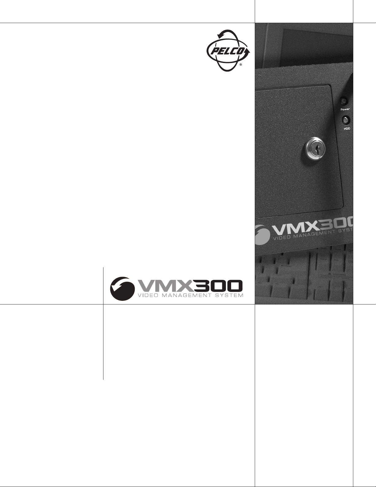
-4 MODEL WORKSTATIONS
1. Using a BNC video cable (not supplied), connect the video source to the first BNC video port on the rear panel (the top port).
2. Connect up to three additional video sources, using the BNC video ports in sequential order (from top to bottom).
When you configure settings in the server software for this workstation, add a custom window for each video input, and then configure a Quad Video
Display DS canvas for each window. Refer to the VMX300(-E) Server Configuration manual (C1553M) for detailed instructions.
VIDEO INPUT 1
VIDEO INPUT 2
VIDEO INPUT 3
VIDEO INPUT 4
Figure 6. How to Connect Analog Video to a -4 Model Workstation
C1563M (2/08) 3
Page 4

Worldwide Headquarters
3500 Pelco Way
Clovis, California 93612 USA
USA & Canada
Tel: 800/289-9100
Fax: 800/289-9150
International
Tel: 1-559/292-1981
Fax: 1-559/348-1120
www.pelco.com
ISO9001
Australia|Finland|France|Germany|Italy|Macau|The Netherlands|Russia|Singapore
South Africa
The materials used in the manufacture of this document and its components are compliant to the requirements of Directive 2002/95/EC.
Pelco and the Pelco logo are registered trad emarks of Pelco, Inc. ©Copyright 2008, Pelco, Inc. All rights reserved.
Microsoft, Windows, and Video for Windows are registered trademarks of Microsoft Corporation.
C1563M (2/08)
Spain|Sweden|United Arab Emirates|United Kingdom|United States
|
Page 5
Installation Manual
C1552M-C (7/07)
Page 6

Page 7

Contents
Important Safety Instructions . . . . . . . . . . . . . . . . . . . . . . . . . . . . . . . . . . . . . . . . . . . . . . . . . . . . . . . . . . . . . . . . . . . . . . . . . . . . . . . . . . . . . . . . . . . . 5
Regulatory Notices . . . . . . . . . . . . . . . . . . . . . . . . . . . . . . . . . . . . . . . . . . . . . . . . . . . . . . . . . . . . . . . . . . . . . . . . . . . . . . . . . . . . . . . . . . . . . . . . . . . . 6
Video Quality Caution . . . . . . . . . . . . . . . . . . . . . . . . . . . . . . . . . . . . . . . . . . . . . . . . . . . . . . . . . . . . . . . . . . . . . . . . . . . . . . . . . . . . . . . . . . . . . . . . . . 6
Description. . . . . . . . . . . . . . . . . . . . . . . . . . . . . . . . . . . . . . . . . . . . . . . . . . . . . . . . . . . . . . . . . . . . . . . . . . . . . . . . . . . . . . . . . . . . . . . . . . . . . . . . . . . 7
Models . . . . . . . . . . . . . . . . . . . . . . . . . . . . . . . . . . . . . . . . . . . . . . . . . . . . . . . . . . . . . . . . . . . . . . . . . . . . . . . . . . . . . . . . . . . . . . . . . . . . . . . . . 8
Compatible Products. . . . . . . . . . . . . . . . . . . . . . . . . . . . . . . . . . . . . . . . . . . . . . . . . . . . . . . . . . . . . . . . . . . . . . . . . . . . . . . . . . . . . . . . . . . . . . 10
Documentation Resources . . . . . . . . . . . . . . . . . . . . . . . . . . . . . . . . . . . . . . . . . . . . . . . . . . . . . . . . . . . . . . . . . . . . . . . . . . . . . . . . . . . . . . . . . 10
Typical Applications. . . . . . . . . . . . . . . . . . . . . . . . . . . . . . . . . . . . . . . . . . . . . . . . . . . . . . . . . . . . . . . . . . . . . . . . . . . . . . . . . . . . . . . . . . . . . . . . . . . 11
Matrix Switchers . . . . . . . . . . . . . . . . . . . . . . . . . . . . . . . . . . . . . . . . . . . . . . . . . . . . . . . . . . . . . . . . . . . . . . . . . . . . . . . . . . . . . . . . . . . . . . . . 11
DX8000 and DX9000 Series DVRs . . . . . . . . . . . . . . . . . . . . . . . . . . . . . . . . . . . . . . . . . . . . . . . . . . . . . . . . . . . . . . . . . . . . . . . . . . . . . . . . . . . 14
PelcoNet Transmission Systems . . . . . . . . . . . . . . . . . . . . . . . . . . . . . . . . . . . . . . . . . . . . . . . . . . . . . . . . . . . . . . . . . . . . . . . . . . . . . . . . . . . . 16
NVR300 Network Video Recorder . . . . . . . . . . . . . . . . . . . . . . . . . . . . . . . . . . . . . . . . . . . . . . . . . . . . . . . . . . . . . . . . . . . . . . . . . . . . . . . . . . . 19
Installation . . . . . . . . . . . . . . . . . . . . . . . . . . . . . . . . . . . . . . . . . . . . . . . . . . . . . . . . . . . . . . . . . . . . . . . . . . . . . . . . . . . . . . . . . . . . . . . . . . . . . . . . . . 20
Parts List . . . . . . . . . . . . . . . . . . . . . . . . . . . . . . . . . . . . . . . . . . . . . . . . . . . . . . . . . . . . . . . . . . . . . . . . . . . . . . . . . . . . . . . . . . . . . . . . . . . . . . 20
User-Supplied Parts . . . . . . . . . . . . . . . . . . . . . . . . . . . . . . . . . . . . . . . . . . . . . . . . . . . . . . . . . . . . . . . . . . . . . . . . . . . . . . . . . . . . . . . . . . . . . . 20
Mounting . . . . . . . . . . . . . . . . . . . . . . . . . . . . . . . . . . . . . . . . . . . . . . . . . . . . . . . . . . . . . . . . . . . . . . . . . . . . . . . . . . . . . . . . . . . . . . . . . . . . . . . . . . . 21
VMX300 Models . . . . . . . . . . . . . . . . . . . . . . . . . . . . . . . . . . . . . . . . . . . . . . . . . . . . . . . . . . . . . . . . . . . . . . . . . . . . . . . . . . . . . . . . . . . . . 8
VMX300-E Models. . . . . . . . . . . . . . . . . . . . . . . . . . . . . . . . . . . . . . . . . . . . . . . . . . . . . . . . . . . . . . . . . . . . . . . . . . . . . . . . . . . . . . . . . . . . 9
VMX300E-B Backup Server . . . . . . . . . . . . . . . . . . . . . . . . . . . . . . . . . . . . . . . . . . . . . . . . . . . . . . . . . . . . . . . . . . . . . . . . . . . . . . . . . . . . 10
Front View . . . . . . . . . . . . . . . . . . . . . . . . . . . . . . . . . . . . . . . . . . . . . . . . . . . . . . . . . . . . . . . . . . . . . . . . . . . . . . . . . . . . . . . . . . . . . . . . . . . . . . . . . . 22
Rear View. . . . . . . . . . . . . . . . . . . . . . . . . . . . . . . . . . . . . . . . . . . . . . . . . . . . . . . . . . . . . . . . . . . . . . . . . . . . . . . . . . . . . . . . . . . . . . . . . . . . . . . . . . . 23
VMX300(-E) Connections . . . . . . . . . . . . . . . . . . . . . . . . . . . . . . . . . . . . . . . . . . . . . . . . . . . . . . . . . . . . . . . . . . . . . . . . . . . . . . . . . . . . . . . . . . . . . . . 24
VMX300(-E) Connections to the Network. . . . . . . . . . . . . . . . . . . . . . . . . . . . . . . . . . . . . . . . . . . . . . . . . . . . . . . . . . . . . . . . . . . . . . . . . . . . . . 24
VMX300(-E) Keyboard and Mouse . . . . . . . . . . . . . . . . . . . . . . . . . . . . . . . . . . . . . . . . . . . . . . . . . . . . . . . . . . . . . . . . . . . . . . . . . . . . . . . . . . . 24
VMX300(-E) Monitor Outputs . . . . . . . . . . . . . . . . . . . . . . . . . . . . . . . . . . . . . . . . . . . . . . . . . . . . . . . . . . . . . . . . . . . . . . . . . . . . . . . . . . . . . . . 25
VMX300(-E) Analog Video Inputs . . . . . . . . . . . . . . . . . . . . . . . . . . . . . . . . . . . . . . . . . . . . . . . . . . . . . . . . . . . . . . . . . . . . . . . . . . . . . . . . . . . . 26
-1 Model Workstations . . . . . . . . . . . . . . . . . . . . . . . . . . . . . . . . . . . . . . . . . . . . . . . . . . . . . . . . . . . . . . . . . . . . . . . . . . . . . . . . . . . . . . . 26
-4 Model Workstations . . . . . . . . . . . . . . . . . . . . . . . . . . . . . . . . . . . . . . . . . . . . . . . . . . . . . . . . . . . . . . . . . . . . . . . . . . . . . . . . . . . . . . . 26
External Devices . . . . . . . . . . . . . . . . . . . . . . . . . . . . . . . . . . . . . . . . . . . . . . . . . . . . . . . . . . . . . . . . . . . . . . . . . . . . . . . . . . . . . . . . . . . . . . . . . 27
KBD300A Keyboard . . . . . . . . . . . . . . . . . . . . . . . . . . . . . . . . . . . . . . . . . . . . . . . . . . . . . . . . . . . . . . . . . . . . . . . . . . . . . . . . . . . . . . . . . . 29
Spectra/Esprit Control Connections . . . . . . . . . . . . . . . . . . . . . . . . . . . . . . . . . . . . . . . . . . . . . . . . . . . . . . . . . . . . . . . . . . . . . . . . . . . . . 32
CM6700 Switcher . . . . . . . . . . . . . . . . . . . . . . . . . . . . . . . . . . . . . . . . . . . . . . . . . . . . . . . . . . . . . . . . . . . . . . . . . . . . . . . . . . . . . . . . . . . 33
CM6800 Switcher . . . . . . . . . . . . . . . . . . . . . . . . . . . . . . . . . . . . . . . . . . . . . . . . . . . . . . . . . . . . . . . . . . . . . . . . . . . . . . . . . . . . . . . . . . . 34
CM9700 Matrix Switching Systems . . . . . . . . . . . . . . . . . . . . . . . . . . . . . . . . . . . . . . . . . . . . . . . . . . . . . . . . . . . . . . . . . . . . . . . . . . . . . 36
CM9760-ALM Alarm Interface Unit. . . . . . . . . . . . . . . . . . . . . . . . . . . . . . . . . . . . . . . . . . . . . . . . . . . . . . . . . . . . . . . . . . . . . . . . . . . . . . 38
CM9760-REL Relay Interface Unit . . . . . . . . . . . . . . . . . . . . . . . . . . . . . . . . . . . . . . . . . . . . . . . . . . . . . . . . . . . . . . . . . . . . . . . . . . . . . . . 39
Serial Output Device . . . . . . . . . . . . . . . . . . . . . . . . . . . . . . . . . . . . . . . . . . . . . . . . . . . . . . . . . . . . . . . . . . . . . . . . . . . . . . . . . . . . . . . . . 40
IP-Based Devices . . . . . . . . . . . . . . . . . . . . . . . . . . . . . . . . . . . . . . . . . . . . . . . . . . . . . . . . . . . . . . . . . . . . . . . . . . . . . . . . . . . . . . . . . . . . 40
Power Cables . . . . . . . . . . . . . . . . . . . . . . . . . . . . . . . . . . . . . . . . . . . . . . . . . . . . . . . . . . . . . . . . . . . . . . . . . . . . . . . . . . . . . . . . . . . . . . . . . . . 41
Appendix . . . . . . . . . . . . . . . . . . . . . . . . . . . . . . . . . . . . . . . . . . . . . . . . . . . . . . . . . . . . . . . . . . . . . . . . . . . . . . . . . . . . . . . . . . . . . . . . . . . . . . . . . . . 42
Changing the Port Settings of a VMX300(-E) COM Port. . . . . . . . . . . . . . . . . . . . . . . . . . . . . . . . . . . . . . . . . . . . . . . . . . . . . . . . . . . . . . . . . . . 42
Specifications . . . . . . . . . . . . . . . . . . . . . . . . . . . . . . . . . . . . . . . . . . . . . . . . . . . . . . . . . . . . . . . . . . . . . . . . . . . . . . . . . . . . . . . . . . . . . . . . . . . . . . . 43
C1552M-C (7/07) 3
Page 8

List of Illustrations
1 Sample VMX300(-E) System with Matrix Switchers . . . . . . . . . . . . . . . . . . . . . . . . . . . . . . . . . . . . . . . . . . . . . . . . . . . . . . . . . . . . . . . . . . . 11
2 Pelco ASCII Switchers . . . . . . . . . . . . . . . . . . . . . . . . . . . . . . . . . . . . . . . . . . . . . . . . . . . . . . . . . . . . . . . . . . . . . . . . . . . . . . . . . . . . . . . . . . 12
3 Pelco’s Non-Native ASCII Switchers . . . . . . . . . . . . . . . . . . . . . . . . . . . . . . . . . . . . . . . . . . . . . . . . . . . . . . . . . . . . . . . . . . . . . . . . . . . . . . . 12
4 Two Cameras Controlled by Different Device Drivers . . . . . . . . . . . . . . . . . . . . . . . . . . . . . . . . . . . . . . . . . . . . . . . . . . . . . . . . . . . . . . . . . . 13
5 Coaxitron and Fixed Camera Transmission . . . . . . . . . . . . . . . . . . . . . . . . . . . . . . . . . . . . . . . . . . . . . . . . . . . . . . . . . . . . . . . . . . . . . . . . . . 13
6 Looping Camera Outputs . . . . . . . . . . . . . . . . . . . . . . . . . . . . . . . . . . . . . . . . . . . . . . . . . . . . . . . . . . . . . . . . . . . . . . . . . . . . . . . . . . . . . . . . 14
7 Sample VMX300(-E) System with DVRs . . . . . . . . . . . . . . . . . . . . . . . . . . . . . . . . . . . . . . . . . . . . . . . . . . . . . . . . . . . . . . . . . . . . . . . . . . . . 14
8 Connecting a DVR: Method 1. . . . . . . . . . . . . . . . . . . . . . . . . . . . . . . . . . . . . . . . . . . . . . . . . . . . . . . . . . . . . . . . . . . . . . . . . . . . . . . . . . . . . 15
9 Connecting a DVR: Method 2. . . . . . . . . . . . . . . . . . . . . . . . . . . . . . . . . . . . . . . . . . . . . . . . . . . . . . . . . . . . . . . . . . . . . . . . . . . . . . . . . . . . . 15
10 Example 1 of a PelcoNet Configuration . . . . . . . . . . . . . . . . . . . . . . . . . . . . . . . . . . . . . . . . . . . . . . . . . . . . . . . . . . . . . . . . . . . . . . . . . . . . . 16
11 Example 2 of a PelcoNet Configuration . . . . . . . . . . . . . . . . . . . . . . . . . . . . . . . . . . . . . . . . . . . . . . . . . . . . . . . . . . . . . . . . . . . . . . . . . . . . . 17
12 Example 3 of a PelcoNet Configuration . . . . . . . . . . . . . . . . . . . . . . . . . . . . . . . . . . . . . . . . . . . . . . . . . . . . . . . . . . . . . . . . . . . . . . . . . . . . . 18
13 Sample VMX300(-E) System with the NVR300 . . . . . . . . . . . . . . . . . . . . . . . . . . . . . . . . . . . . . . . . . . . . . . . . . . . . . . . . . . . . . . . . . . . . . . . 19
14 Rack Mount Installation . . . . . . . . . . . . . . . . . . . . . . . . . . . . . . . . . . . . . . . . . . . . . . . . . . . . . . . . . . . . . . . . . . . . . . . . . . . . . . . . . . . . . . . . . 21
15 VMX300(-E) Front View . . . . . . . . . . . . . . . . . . . . . . . . . . . . . . . . . . . . . . . . . . . . . . . . . . . . . . . . . . . . . . . . . . . . . . . . . . . . . . . . . . . . . . . . . 22
16 VMX300(-E) Rear View. . . . . . . . . . . . . . . . . . . . . . . . . . . . . . . . . . . . . . . . . . . . . . . . . . . . . . . . . . . . . . . . . . . . . . . . . . . . . . . . . . . . . . . . . . 23
17 Network Connection. . . . . . . . . . . . . . . . . . . . . . . . . . . . . . . . . . . . . . . . . . . . . . . . . . . . . . . . . . . . . . . . . . . . . . . . . . . . . . . . . . . . . . . . . . . . 24
18 Keyboard and Mouse Connections . . . . . . . . . . . . . . . . . . . . . . . . . . . . . . . . . . . . . . . . . . . . . . . . . . . . . . . . . . . . . . . . . . . . . . . . . . . . . . . . 24
19 Monitor Port Adapter Connection . . . . . . . . . . . . . . . . . . . . . . . . . . . . . . . . . . . . . . . . . . . . . . . . . . . . . . . . . . . . . . . . . . . . . . . . . . . . . . . . . 25
20 How to Connect Monitors to a VMX300(-E) Workstation . . . . . . . . . . . . . . . . . . . . . . . . . . . . . . . . . . . . . . . . . . . . . . . . . . . . . . . . . . . . . . . 25
21 How to Connect a Single Monitor to a VMX300(-E) Workstation . . . . . . . . . . . . . . . . . . . . . . . . . . . . . . . . . . . . . . . . . . . . . . . . . . . . . . . . . 25
22 How to Connect Analog Video to a -1 Model Workstation . . . . . . . . . . . . . . . . . . . . . . . . . . . . . . . . . . . . . . . . . . . . . . . . . . . . . . . . . . . . . . 26
23 How to Connect Analog Video to a -4 Model Workstation . . . . . . . . . . . . . . . . . . . . . . . . . . . . . . . . . . . . . . . . . . . . . . . . . . . . . . . . . . . . . . 26
24 Sample of a Direct Serial Connection for an External Device. . . . . . . . . . . . . . . . . . . . . . . . . . . . . . . . . . . . . . . . . . . . . . . . . . . . . . . . . . . . 27
25 VMX300(-E) RS-422 Wall Block Connection . . . . . . . . . . . . . . . . . . . . . . . . . . . . . . . . . . . . . . . . . . . . . . . . . . . . . . . . . . . . . . . . . . . . . . . . . 28
26 Sample of an Internet Protocol Connection for an External Device . . . . . . . . . . . . . . . . . . . . . . . . . . . . . . . . . . . . . . . . . . . . . . . . . . . . . . . 28
27 KBD300A: Direct Serial Connection . . . . . . . . . . . . . . . . . . . . . . . . . . . . . . . . . . . . . . . . . . . . . . . . . . . . . . . . . . . . . . . . . . . . . . . . . . . . . . . . 29
28 KBD300A: IP Connection . . . . . . . . . . . . . . . . . . . . . . . . . . . . . . . . . . . . . . . . . . . . . . . . . . . . . . . . . . . . . . . . . . . . . . . . . . . . . . . . . . . . . . . . 30
29 KBD300A Keyboard Rear Panel . . . . . . . . . . . . . . . . . . . . . . . . . . . . . . . . . . . . . . . . . . . . . . . . . . . . . . . . . . . . . . . . . . . . . . . . . . . . . . . . . . . 30
30 Spectra/Esprit Control Connections. . . . . . . . . . . . . . . . . . . . . . . . . . . . . . . . . . . . . . . . . . . . . . . . . . . . . . . . . . . . . . . . . . . . . . . . . . . . . . . . 32
31 CM6700 Connections . . . . . . . . . . . . . . . . . . . . . . . . . . . . . . . . . . . . . . . . . . . . . . . . . . . . . . . . . . . . . . . . . . . . . . . . . . . . . . . . . . . . . . . . . . . 33
32 CM6800 RJ-45 Connections. . . . . . . . . . . . . . . . . . . . . . . . . . . . . . . . . . . . . . . . . . . . . . . . . . . . . . . . . . . . . . . . . . . . . . . . . . . . . . . . . . . . . . 34
33 CM6800 DB9 Connections . . . . . . . . . . . . . . . . . . . . . . . . . . . . . . . . . . . . . . . . . . . . . . . . . . . . . . . . . . . . . . . . . . . . . . . . . . . . . . . . . . . . . . . 35
34 CM9700 RS-422 Connections . . . . . . . . . . . . . . . . . . . . . . . . . . . . . . . . . . . . . . . . . . . . . . . . . . . . . . . . . . . . . . . . . . . . . . . . . . . . . . . . . . . . 36
35 CM9700 RS-232 Connections . . . . . . . . . . . . . . . . . . . . . . . . . . . . . . . . . . . . . . . . . . . . . . . . . . . . . . . . . . . . . . . . . . . . . . . . . . . . . . . . . . . . 37
36 CM9760-ALM Direct Serial Connection. . . . . . . . . . . . . . . . . . . . . . . . . . . . . . . . . . . . . . . . . . . . . . . . . . . . . . . . . . . . . . . . . . . . . . . . . . . . . 38
37 CM9760-REL Direct Serial Connection . . . . . . . . . . . . . . . . . . . . . . . . . . . . . . . . . . . . . . . . . . . . . . . . . . . . . . . . . . . . . . . . . . . . . . . . . . . . . 39
38 Sample IP-Based Device Connection . . . . . . . . . . . . . . . . . . . . . . . . . . . . . . . . . . . . . . . . . . . . . . . . . . . . . . . . . . . . . . . . . . . . . . . . . . . . . . . 40
39 Opening the COM Port Properties Dialog Box . . . . . . . . . . . . . . . . . . . . . . . . . . . . . . . . . . . . . . . . . . . . . . . . . . . . . . . . . . . . . . . . . . . . . . . . 42
40 COM Port Properties: Port Settings Tab. . . . . . . . . . . . . . . . . . . . . . . . . . . . . . . . . . . . . . . . . . . . . . . . . . . . . . . . . . . . . . . . . . . . . . . . . . . . . 42
List of Tables
A VMX300 Model Numbers. . . . . . . . . . . . . . . . . . . . . . . . . . . . . . . . . . . . . . . . . . . . . . . . . . . . . . . . . . . . . . . . . . . . . . . . . . . . . . . . . . . . . . . . . 8
B VMX300 Sample Licensing Configurations . . . . . . . . . . . . . . . . . . . . . . . . . . . . . . . . . . . . . . . . . . . . . . . . . . . . . . . . . . . . . . . . . . . . . . . . . . . 8
C VMX300-E Model Numbers . . . . . . . . . . . . . . . . . . . . . . . . . . . . . . . . . . . . . . . . . . . . . . . . . . . . . . . . . . . . . . . . . . . . . . . . . . . . . . . . . . . . . . . 9
D VMX300-E Sample Licensing Configurations . . . . . . . . . . . . . . . . . . . . . . . . . . . . . . . . . . . . . . . . . . . . . . . . . . . . . . . . . . . . . . . . . . . . . . . . . 9
E VMX300E-B Sample Licensing Configurations . . . . . . . . . . . . . . . . . . . . . . . . . . . . . . . . . . . . . . . . . . . . . . . . . . . . . . . . . . . . . . . . . . . . . . . 10
F Default Settings for VMX300(-E) COM Ports . . . . . . . . . . . . . . . . . . . . . . . . . . . . . . . . . . . . . . . . . . . . . . . . . . . . . . . . . . . . . . . . . . . . . . . . . 27
G VMX300(-E) COM Port Pin Assignments . . . . . . . . . . . . . . . . . . . . . . . . . . . . . . . . . . . . . . . . . . . . . . . . . . . . . . . . . . . . . . . . . . . . . . . . . . . . 27
H Keyboard Address Switch Settings . . . . . . . . . . . . . . . . . . . . . . . . . . . . . . . . . . . . . . . . . . . . . . . . . . . . . . . . . . . . . . . . . . . . . . . . . . . . . . . . 31
I Keyboard Mode Switch Settings . . . . . . . . . . . . . . . . . . . . . . . . . . . . . . . . . . . . . . . . . . . . . . . . . . . . . . . . . . . . . . . . . . . . . . . . . . . . . . . . . . 31
J Recommended CM6800 Port for VMX300(-E) Connection. . . . . . . . . . . . . . . . . . . . . . . . . . . . . . . . . . . . . . . . . . . . . . . . . . . . . . . . . . . . . . . 34
4 C1552M-C (7/07)
Page 9

Important Safety Instructions
1. Read these instructions.
2. Keep these instructions.
3. Heed all warnings.
4. Follow all instructions.
5. Do not use this apparatus near water.
6. Clean only with dry cloth.
7. Do not block any ventilation openings. Install in accordance with the manufacturer’s instructions.
8. Do not install near any heat sources such as radiators, heat registers, stoves, or other apparatus (including amplifiers) that produce heat.
9. Do not defeat the safety purpose of the polarized or grounding-type plug. A polarized plug has two blades with one wider than the other.
A grounding plug has two blades and a third grounding prong. The wide blade or the third prong are provided for your safety. If the provided
plug does not fit into your outlet consult an electrician for replacement of the obsolete outlet.
10. Protect the power cord from being walked on or pinched particularly at plugs, convenience receptacles, and the points where they exit from
the apparatus.
11. Only use attachments/accessories specified by the manufacturer.
12. Use only with the cart, stand, tripod, bracket, or table specified by the manufacturer, or sold with the apparatus. When a cart is used, use
caution when moving the cart/apparatus combination to avoid injury from tip-over.
13. Refer all servicing to qualified service personnel. Servicing is required when the apparatus has been damaged in any way, such as
power-supply cord or plug is damaged, liquid has been spilled or objects have fallen into the apparatus, the apparatus has been exposed to
rain or moisture, does not operate normally, or has been dropped.
14. Apparatus shall not be exposed to dripping or splashing and that no objects filled with liquids, such as vases shall be placed on the
apparatus.
15. WARNING: To reduce the risk of fire or electric shock, do not expose this apparatus to rain or moisture.
16. Installation should be done only by qualified personnel and conform to all local codes.
17. Unless the unit is specifically marked as a NEMA Type 3, 3R, 3S, 4, 4X, 6, or 6P enclosure, it is designed for indoor use only and it must not
be installed where exposed to rain and moisture.
18. Use only installation methods and materials capable of supporting four times the maximum specified load.
19. A readily accessible disconnect device shall be incorporated in the building installation wiring.
20. The socket-outlet shall be installed near the equipment and shall be easily accessible.
21. A CCC-approved power cord must be used to power this equipment when used in China.
CAUTION: These servicing instructions are for use by qualified service personnel only. To reduce the risk of electric shock do not perform any
servicing other that contained in the operating instructions unless you are qualified to do so.
CAUTION: Danger of explosion if battery is incorrectly replaced. Replace only with the same or equivalent type. Dispose of used batteries
according to the instructions provided by the battery manufacturer.
Only use replacement parts recommended by Pelco.
The product and/or manual may bear the following marks:
This symbol indicates that dangerous voltage constituting a risk of electric shock is
present within this unit.
This symbol indicates that there are important operating and maintenance instructions
in the literature accompanying this unit.
C1552M-C (7/07) 5
CAUTION:
RISK OF ELECTRIC SHOCK.
DO NOT OPEN.
Page 10

Regulatory Notices
This device complies with Part 15 of the FCC Rules. Operation is subject to the following two conditions: (1) this device may not cause harmful
interference, and (2) this device must accept any interference received, including interference that may cause undesired operation.
RADIO AND TELEVISION INTERFERENCE
This equipment has been tested and found to comply with the limits of a Class A digital device, pursuant to Part 15 of the FCC Rules. These limits
are designed to provide reasonable protection against harmful interference when the equipment is operated in a commercial environment. This
equipment generates, uses, and can radiate radio frequency energy and, if not installed and used in accordance with the instruction manual, may
cause harmful interference to radio communications. Operation of this equipment in a residential area is likely to cause harmful interference in
which case the user will be required to correct the interference at his own expense.
Changes and Modifications not expressly approved by the manufacturer or registrant of this equipment can void your authority to operate this
equipment under Federal Communications Commission’s rules.
In order to maintain compliance with FCC regulations shielded cables must be used with this equipment. Operation with non-approved equipment
or unshielded cables is likely to result in interference to radio and television reception.
This Class A digital apparatus complies with Canadian ICES-003.
Cet appareil numérique de la classe A est conforme à la norme NMB-003 du Canada.
Video Quality Caution
Frame Rate Notice Regarding User-Selected Options
Pelco systems are capable of providing high quality video for both live viewing and playback. However, the systems can be used in lower quality
modes, which can degrade picture quality, to allow for a slower rate of data transfer and to reduce the amount of video data stored. The picture
quality can be degraded by either lowering the resolution, reducing the picture rate, or both. A picture degraded by having a reduced resolution
may result in an image that is less clear or even indiscernible. A picture degraded by reducing the picture rate has fewer frames per second,
which can result in images that appear to jump or move more quickly than normal during playback. Lower frame rates may result in a key event
not being recorded by the system.
Judgment as to the suitability of the products for users’ purposes is solely the users’ responsibility. Users shall determine the suitability of the
products for their own intended application, picture rate and picture quality. In the event users intend to use the video for evidentiary purposes in
a judicial proceeding or otherwise, users should consult with their attorney regarding any particular requirements for such use.
6 C1552M-C (7/07)
Page 11

Description
The Pelco VMX300(-E) video management system uses a Windows®-based interface to control any combination of analog and IP devices in a
single integrated video security system. With a mouse, you can click a camera icon on a system map and then drag it to a video display window.
Mapping configurations and a visual interface allow you to easily control the following devices:
• Matrix switchers (CM6700, CM6800, CM9740, CM9760, CM9770, CM9780)
• PelcoNet
• DX8000 (software version level 1.1.00.1121 or higher) and DX9000 Series digital video recorders
• NVR300 Series network video recorders
• Spectra
• CM9760-ALM and CM9760-REL input/output devices
VMX300 provides control and monitoring of CCTV equipment in a client-to-server configuration. VMX300-E provides control and monitoring of
CCTV equipment in the following configurations: client-to-server; multiple clients-to-server; client-to-multiple servers; or server-to-server.
Each VMX300(-E) system must have at least one workstation with server software. Workstations with server software always include client
software and, therefore, are called client/server workstations. A VMX300 system can have only one client/server workstation. A VMX300-E
system can have multiple client/server workstations.
Each VMX300(-E) system must have at least one workstation with client software. This can be the client/server workstation, described above, or
you can add a separate workstation with only client software to the system. Each VMX300(-E) system can have multiple client workstations in
addition to the client/server workstation.
Your system administrator configures your system using the VMX300(-E) server software, and then launches the VMX300(-E) server into “run”
mode. A system operator uses the VMX300(-E) client software to view and control the area under surveillance. The operator can connect to the
VMX300(-E) system from the client/server workstation, or from a separate client workstation. With the VMX300-E version, an operator could also
connect from another client/server workstation.
™
MPEG Series transmission systems (NET300 Series, NET350 Series, NET4001A)
®
and Esprit® camera positioning systems
C1552M-C (7/07) 7
Page 12
MODELS
VMX300 and VMX300-E workstations come with software preloaded on a rack mountable PC; keyboard and mouse are included. Each
workstation supports two monitors. (Note: Monitors are not included. A standard VGA or Super VGA monitor can be used.)
VMX300 MODELS
VMX300 provides control and monitoring of CCTV equipment in a client-to-server configuration. A VMX300 workstation can be a client/server
workstation (VMX300-CSVR) or a client workstation (VMX300-CL).
VMX300-CSVR workstations include both client and sever software applications. The model comes standard with licensing for the server and
client and up to 10 cameras. Licenses for up to 100 cameras can be purchased as needed.
VMX300-CL workstations include the client software application and the licensing (five per client) required for the client workstation to connect
to the server. Up to 10 additional client workstations can be connected to the VMX300 server. Note that each client added to the system
decreases the potential number of cameras (by five) that you can add to the system.
NOTE: If your system requires only one client, the client and server applications can both run on the same workstation. To optimize system
performance in a multiple-client system, each client application should run from a dedicated client workstation.
Refer to Table A for a list of VMX300 model numbers.
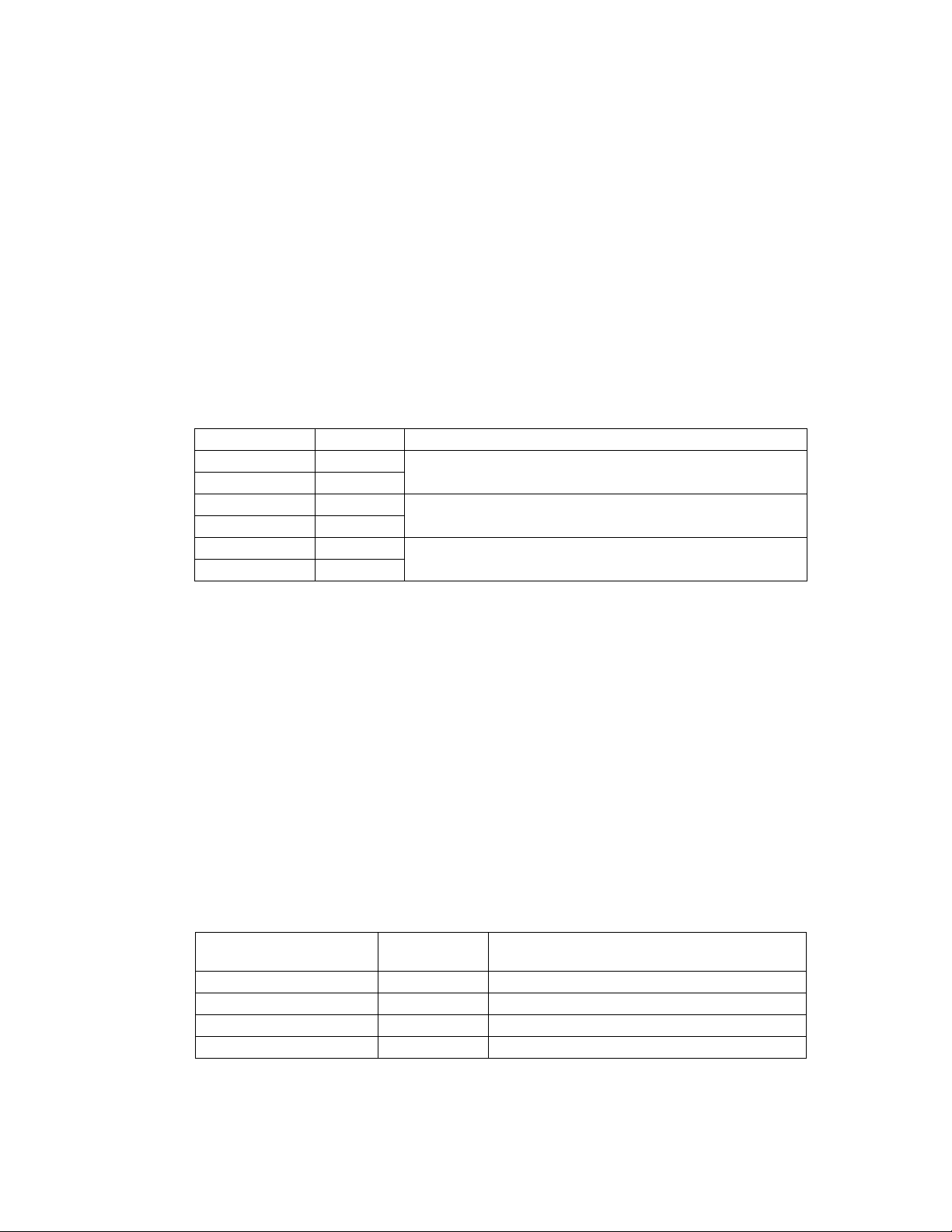
Table A. VMX300 Model Numbers
Model Type Video Windows Supported
VMX300-CSVR-0 Client/Server
VMX300-CL-0 Client
VMX300-CSVR-1 Client/Server
VMX300-CL-1 Client
VMX300-CSVR-4 Client/Server
VMX300-CL-4 Client
*The VMX300 software allows you to view both analog and digital video display windows simultaneously on the same
system monitor, as follows:
Analog windows: The analog video display window described in the -1 and -4 models typically allows operators to
view video from a camera, matrix switcher, or other analog video source connected directly to the VMX300 rear panel.
The -0 models can receive analog video inputs only through PelcoNet video encoders and Pelco DX8000 and DX9000
Series DVRs, using a network connection.
Digital windows: The number of digital video display windows that can be displayed at one time is limited by the size
and type of images selected for viewing. Refer to Table B in the VMX300 Software Guide for an overview of the CPU
workload and bandwidth amounts used for each type of video stream (the video in a custom window).
Digital video windows only
One analog video input, one analog video display window,* and multiple
digital video display windows.*
Four analog video inputs, four analog video display windows,* and multiple
digital video display windows.*
VMX300 Software Licenses
The VMX300 can support a maximum of 100 licenses. Licenses can be used for cameras (one each), KBD300A keyboards (five each), and clients
(five each; supplied with client workstation).
VMX300-LIC-10 10 additional licenses
VMX300-LIC-20 20 additional licenses
VMX300-LIC-50 50 additional licenses
VMX300-LIC-100 100 additional licenses
Table B. VMX300 Sample Licensing Configurations
System Configuration Licenses Used
Client/Server Workstation Base license 100
1 additional client workstation 5 95
2 additional client workstations 10 85
10 additional client workstations 50 50 (cameras only)
8 C1552M-C (7/07)
Licenses Available for Cameras, KBD300A Keyboards,
or Additional Client Workstations
Page 13
VMX300-E MODELS
VMX300-E provides control and monitoring of CCTV equipment in the following configurations: client-to-server; multiple clients-to-server;
client-to-multiple servers; or server-to-server. A VMX300-E workstation can be a client/server workstation (VMX300-E-CSVR) or a client
workstation (VMX300-E-CL).
VMX300-E-CSVR workstations include both the client and server software applications. The model comes standard with licensing for the server
and client and up to 10 cameras. Licenses for up to 2,000 cameras can be purchased as needed.
VMX300-E-CL workstations include the client software application and the licensing (10 per client) required for the client workstation to connect
to the server. Up to 50 additional client workstations can be connected to the VMX300-E server. Note that each client added to the system
decreases the potential number of cameras (by ten) that you can add to the system.
NOTE: If your system requires only one client, the client and server applications can both run on the same workstation. To optimize system
performance in a multiple-client system, each client application should run from a dedicated client workstation. Additional servers in the same
system should be run from dedicated server workstations as well.
Refer to Table C for a list of VMX300-E model numbers.
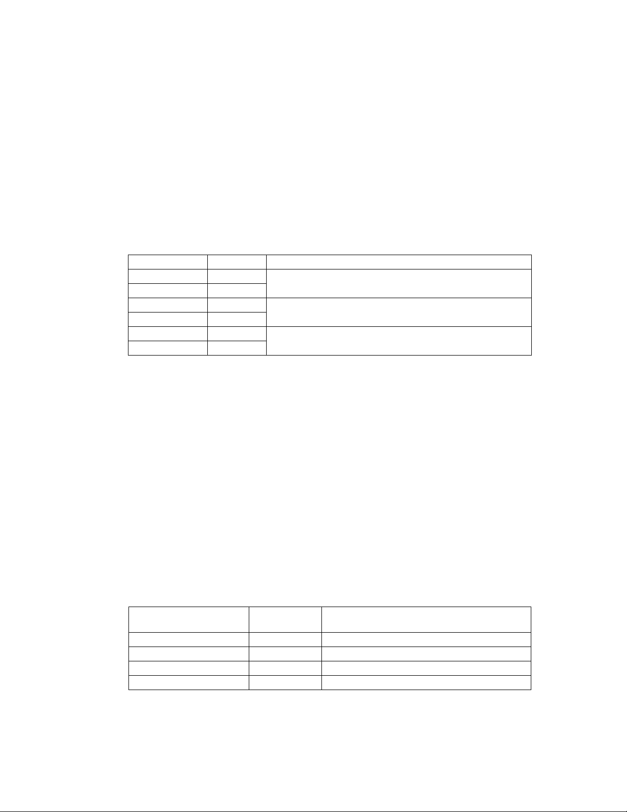
Table C. VMX300-E Model Numbers
Model Type Video Windows Supported
VMX300-E-CSVR-0 Client/Server
VMX300-E-CL-0 Client
VMX300-E-CSVR-1 Client/Server
VMX300-E-CL-1 Client
VMX300-E-CSVR-4 Client/Server
VMX300-E-CL-4 Client
*The VMX300-E software allows you to view both analog and digital video display windows simultaneously on the same
system monitor, as follows:
Analog windows: The analog video display window described in the -1 and -4 models typically allows operators to
view video from a camera, matrix switcher, or other analog video source connected directly to the VMX300-E rear panel.
The -0 models can receive analog video inputs only through PelcoNet video encoders and Pelco DX8000 and DX9000
Series DVRs, using a network connection.
Digital windows: The number of digital video display windows that can be displayed at one time is limited by the size
and type of images selected for viewing. Refer to Table B in the VMX300(-E) Software Guide for an overview of the CPU
workload and bandwidth amounts used for each type of video stream (the video in a custom window).
Digital video windows only
One analog video input, one analog video display window,* and multiple
digital video display windows.*
Four analog video inputs, four analog video display windows,* and multiple
digital video display windows.*
VMX300-E Software Licenses
The VMX300-E can support a maximum of 2,000 licenses. Licenses can be used for cameras (one each), KBD300A keyboards (five each), and
clients (ten each; supplied with client workstation).
VMX300-E-LIC10 10 additional licenses
VMX300-E-LIC20 20 additional licenses
VMX300-E-LIC50 50 additional licenses
VMX300-E-LIC100 100 additional licenses
VMX300-E-LIC200 200 additional licenses
VMX300-E-LIC500 500 additional licenses
Table D. VMX300-E Sample Licensing Configurations
System Configuration Licenses Used
Client/Server Workstation Base license 2,000
1 additional client workstation 10 1,990
10 additional client workstations 100 1,900
50 additional client workstations 500 1,500 (cameras only)
C1552M-C (7/07) 9
Licenses Available for Cameras, KBD300A Keyboards,
or Additional Client Workstations
Page 14

VMX300E-B BACKUP SERVER
A VMX300-E system can include an optional VMX300E-B-SVR backup server. VMX300E-B-SVR backup server workstations include the backup
server software application and licensing for the backup server and client and up to 10 cameras. Licenses for up to 2,000 cameras can be
purchased as needed.
NOTE: When using a backup server, the backup licenses must mirror the VMX300-E system. For every camera, KBD300A keyboard, and client in
the system, you must include a backup license.
VMX300E-B Software Licenses
The VMX300E-B-SVR can support a maximum of 2,000 licenses. Licenses can be used for cameras (one each) , KBD300A keyboards (five each),
and clients (ten each).
VMX300E-B-LIC10 10 additional licenses
VMX300E-B-LIC20 20 additional licenses
VMX300E-B-LIC50 50 additional licenses
VMX300E-B-LIC100 100 additional licenses
VMX300E-B-LIC200 200 additional licenses
VMX300E-B-LIC500 500 additional licenses
Table E. VMX300E-B Sample Licensing Configurations
System Configuration Licenses Used
Backup Server Workstation Base license 2,000
1 additional client workstation 10 1,990
10 additional client workstations 100 1,900
50 additional client workstations 500 1,500 (cameras only)
COMPATIBLE PRODUCTS
Switchers CM6700, CM6800, CM9740, CM9760, CM9770, CM9780
Camera systems Spectra, Esprit
PelcoNet transmission systems NET300 Series, NET350 Series, NET4001A
Network video recorders NVR300 Series
Digital video recorders (DVRs) DX8000 Series (DX8000 software version level 1.1.00.1121 only), DX9000 Series
Input/Output devices CM9760-ALM alarm interface unit, CM9760-REL relay interface unit
External keyboard KBD300A
Backup server VMX300E-B-SVR and associated VMX300E-B license packs
DOCUMENTATION RESOURCES
The following set of manuals provide comprehensive instructions and reference information on the VMX300(-E) system:
VMX300(-E) Installation Quick Start Guide This guide provides an overview of hardware connections.
VMX300(-E) Installation Manual This is the hardware installation manual.
VMX300(-E) Software Guide:
Basic Configuration and Operation This guide provides basic instructions on configuring the server and operating the system.
VMX300(-E) Server Configuration Manual This manual is for system administrators responsible for configuring and maintaining VMX300(-E)
VMX300(-E) Client Operation Manual This manual provides comprehensive instructions and reference information for the client
Licenses Available for Cameras, KBD300A Keyboards,
or Additional Client Workstations
servers. The manual provides comprehensive instructions and reference information for the entire
server configuration.
application used by system operators. The sections on workspaces, configuring servers, and remote
desktop servers are also of interest for system administrators.
10 C1552M-C (7/07)
Page 15
Typical Applications
IMPORTANT NOTE. PLEASE READ.
The network implementations in this document are shown as general representations only and are not intended to show detailed network
topologies. Your actual network will differ, requiring changes or perhaps additional network equipment to accommodate the systems as
illustrated. Please contact your local Pelco representative to discuss your specific requirements.
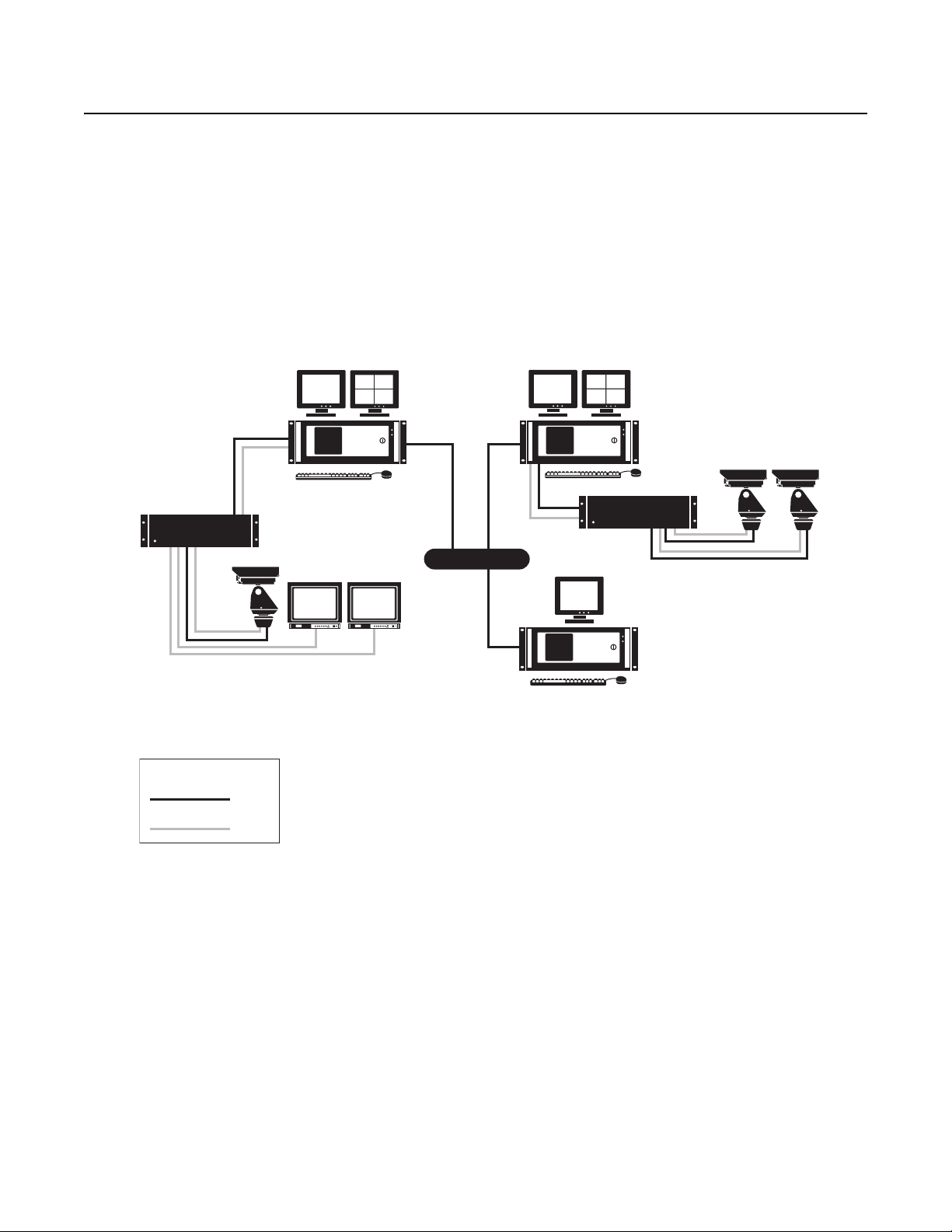
The VMX300(-E) Video Management System can be configured for a wide variety of different applications. The following illustrations provide
some examples of how to use the VMX300(-E) with matrix switchers, DVRs, PelcoNet transmission systems, and NVR300s.
MATRIX SWITCHERS
Figure 1 shows a general example of how to connect a VMX300(-E) to matrix switchers (CM6700, CM6800, CM9740, CM9760, CM9770,
CM9780). Figure 2 on page 12 through Figure 6 on page 14 provide more specific examples of equipment connections.
MATRIX
VMX CLIENT
VMX CLIENT
MATRIX
LEGEND
NETWORK
VMX SERVER
DATA
VIDEO
Figure 1. Sample VMX300(-E) System with Matrix Switchers
C1552M-C (7/07) 11
Page 16

Pelco switchers that include the ASCII protocol in their software communicate directly with the VMX300(-E) workstation, as shown in Figure 2.
The ASCII protocol is native to all of the matrix switchers except for the CM9740 Series and some of the older CM9760 Series switchers. These
non-native switchers require a hardware data translator (CM9760-DT) to translate between the device’s native protocol and the ASCII protocol, as
shown in Figure 3.
CAMERAS
VMX WORKSTATION
LEGEND
DATA
VIDEO
VMX WORKSTATION
NATIVE ASCII SWITCHER
Figure 2. Pelco ASCII Switchers
CAMERA
NON-NATIVE
ASCII SWITCHER
VIDEO DISPLAY DEVICES
CAMERA
CM9760-DT
VIDEO DISPLAY DEVICES
LEGEND
DATA
VIDEO
Figure 3. Pelco’s Non-Native ASCII Switchers
12 C1552M-C (7/07)
Page 17

A controllable camera that is switched through a switcher can either be controlled through the switcher or directly from the VMX300(-E)
workstation. If you want to control the camera through the switcher, connect the camera’s data line to the switcher (refer to Figure 4). If you want
to control the camera from the VMX300(-E) workstation, connect the camera’s data line to the workstation. The video from both cameras is
connected to the switcher.
PTZ CAMERA PTZ CAMERA
VMX WORKSTATION
LEGEND
DATA
VIDEO
SWITCHER
VIDEO DISPLAY DEVICES
Figure 4. Two Cameras Controlled by Different Device Drivers
In Figure 4 video and data are transmitted over separate wires. In Coaxitron
®
transmission, however, both video and data are transmitted over
a single coaxial cable, as illustrated by the camera on the left in Figure 5. Fixed cameras, like the one on the right, are not controllable and
therefore do not transmit data.
VIDEO DISPLAY DEVICES
VMX WORKSTATION
PTZ CAMERA
LEGEND
DATA
VIDEO
COAXITRON
SWITCHER
FIXED CAMERA
Figure 5. Coaxitron and Fixed Camera Transmission
C1552M-C (7/07) 13
Page 18

Video from a camera can be looped through another device, as shown by the solid lines in Figure 6. Looping devices include DVRs, distribution
amplifiers, and monitors.
SWITCHER
VMX WORKSTATION
LEGEND
DATA
VIDEO
DX8000 AND DX9000 SERIES DVRS
Figure 7 shows a sample system with DVRs (DX8000, DX9000).
PTZ CAMERA
LOOPING DEVICE
Figure 6. Looping Camera Outputs
DVR
CAMERA
DVR
LEGEND
DATA
VIDEO
DVR
MATRIX
CAMERA
NETWORK
MATRIX
VMX CLIENT
VMX CLIENT
VMX SERVER
Figure 7. Sample VMX300(-E) System with DVRs
14 C1552M-C (7/07)
Page 19

You can incorporate a DVR into your system using either of the following methods:
• Connect the camera’s video to the DVR, and then connect the DVR’s looping output to the switcher.
PTZ CAMERA
SWITCHER
VMX WORKSTATION
LEGEND
DATA
VIDEO
DVR
Figure 8. Connecting a DVR: Method 1
• Connect the camera’s video directly to the switcher, and then connect the switcher’s looping output to the DVR.
PTZ CAMERA
SWITCHER
VMX WORKSTATION
DVR
LEGEND
DATA
VIDEO
Figure 9. Connecting a DVR: Method 2
C1552M-C (7/07) 15
Page 20

PELCONET TRANSMISSION SYSTEMS
In Figure 10 PelcoNets 1 and 2 encode video from Cameras 1 and 2 respectively for transmission over the network. PelcoNet 3 decodes IP video
from Cameras 1 and 2 for display on the external monitor. PelcoNet 4 decodes video from Cameras 1 and 2 for display on the VMX300(-E) client.
PELCONET 1
PELCONET 3
EXTERNAL MONITOR
LEGEND
CAMERA 1 CAMERA 2
PELCONET 2
VMX SERVER
NETWORK
PELCONET 4
VMX CLIENT
DATA
VIDEO
Figure 10. Example 1 of a PelcoNet Configuration
16 C1552M-C (7/07)
Page 21

In Figure 11 PelcoNets 1 and 2 encode video from Cameras 1 and 2 respectively for transmission over the network. PelcoNet 3 decodes video from
the VMX300(-E) client. The client can also display video from Cameras 3 and 4.
CAMERA 1
CAMERA 2
LEGEND
PELCONET 1
PELCONET 2
DATA
VIDEO
IP NETWORK
NETWORK
VMX SERVER
EXTERNAL MONITOR
PELCONET 3
VMX CLIENT
MATRIX SWITCHER
CAMERAS 3 AND 4
Figure 11. Example 2 of a PelcoNet Configuration
C1552M-C (7/07) 17
Page 22

In Figure 12, PelcoNets 1 and 2 encode video from Cameras 1 and 2 respectively for transmission over the network. PelcoNets 3 and 4 encode
video from Cameras 3 and 4 using the switchers looping outputs. This allows the video to be displayed on Client 1 and recorded on the NVR.
The NVR also records video from Cameras 1 and 2. VMX300(-E) Client 1 displays IP video from all four cameras. Client 2 displays IP video from
Cameras 1 and 2 and analog video from Cameras 3 and 4. The external monitor displays analog video from Cameras 3 and 4.
VMX CLIENT 1
CAMERA 2
VMX CLIENT 2
CAMERA 1
PELCONET 2
LEGEND
PELCONET 1
NVR
DATA
VIDEO
VMX SERVER
NETWORK
EXTERNAL MONITOR
MATRIX SWITCHER
PELCONET 3
PELCONET 4
CAMERA 4
CAMERA 3
Figure 12. Example 3 of a PelcoNet Configuration
18 C1552M-C (7/07)
Page 23

NVR300 NETWORK VIDEO RECORDER
NET4001A ENCODER
LEGEND
DATA
NET350 ENCODER
NVR300
PELCONET DECODER
NET4001A ENCODER
NETWORK
VMX CLIENT 2
VMX SERVER
VMX CLIENT 1
VIDEO
Figure 13. Sample VMX300(-E) System with the NVR300
C1552M-C (7/07) 19
Page 24

Installation
PARTS LIST
Qty Description
1 VMX300 workstation
1Mouse
1 Keyboard
1 VGA adapter
1 RCA-to-BNC video input adapter (-1 models)
2 Power cords (one USA standard and one European standard)
2 Adjustable support rails with screws
2 Mounting brackets with screws and nuts
2 Rack mount ears with screws
2Keys
1 VMX300 Resource CD
USER-SUPPLIED PARTS
In addition to the standard tools and cables required for a video security installation, you will need to provide the following items:
• One or two VGA or SVGA monitors for each VMX300(-E) workstation (the second monitor is optional but recommended). Monitors are not
included with the VMX300(-E), but can be ordered separately from Pelco; any VGA or SVGA monitor can be used.
• (-1 models and -4 models) BNC video cable for connecting analog video sources to the VMX300(-E) workstation.
• Uninterruptible power supply (UPS).
NOTE: When connecting the workstation to a 230 VAC or higher power source, the use of an UPS, such as model PW9120 700i
(manufactured by Powerware
The following parts may be needed, depending on the types of devices you are connecting to the VMX300(-E) workstation (refer to External
Devices on page 27 for details on device connections and user-supplied parts):
• Shielded twisted pairs cable that meets or exceeds the basic requirements for EIA RS-232 applications
• Null modem cable
• RS-232 to RS-422 serial port adapter
®
) or equivalent, is required to comply with CE-marking requirements per EMC Directive 89/336/EEC.
20 C1552M-C (7/07)
Page 25

Mounting
Mount the VMX300(-E) in an EIA-standard 19-inch (48.26 cm) equipment rack, or place it on a flat surface, such as a shelf or table.
Follow these instructions to mount the VMX300(-E) in an equipment rack:
1. Attach the two brackets to both sides of the VMX300(-E).
2. Attach the mounting rails to the equipment rack.
3. Place the workstation onto the mounting rails. It should slide in and out of the rack easily.
4. Fasten the rack ears to the equipment rack.
VMX300(-E)
(4) SCREWS,
10-32 X 0.750-INCH,
PHILLIPS, PAN HEAD
WITH WASHERS
FRONT MOUNTING RAIL
RACK
RACK EAR
REAR MOUNTING RAIL
BRACKET
(SIDE VIEW)
(6) SCREWS, 8-32 X 0.250-INCH,
PAN HEAD
(6) SCREWS,
8-32 X 0.375-INCH,
PAN HEAD WITH
WASHERS
(4) SCREWS,
10-32 X 0.375-INCH,
FLAT HEAD
(8) SCREWS,
10-32 X 0.375-INCH,
FLAT HEAD
SLOTTED HOLES
TOWARD FRONT
OF UNIT
TAPERED ENDS
TOWARD REAR
OF UNIT
Figure 14. Rack Mount Installation
C1552M-C (7/07) 21
Page 26

Front View
Figure 15 illustrates the components on the front of the VMX300(-E) workstation. The unit door can be opened or locked using the supplied keys.
Figure 15. VMX300(-E) Front View
Power LED
HDD (Hard Disk Drive) LED
Key Lock (2 Keys Supplied)
Fan Ventilation
Handle (2)
Rack Ear (2)
Fan
Power Button
DVD/CD-ROM Drive
3.5-inch Floppy Drive
22 C1552M-C (7/07)
Page 27

Rear View
In Figure 16 the rear panel of the VMX300-SYS-4/VMX300-E-SYS-4 workstation is used to identify the components that are common to all models.
Monitor output ports and video input ports are identified for each workstation model in the VMX300(-E) Connections section, starting on page 24.
Figure 16. VMX300(-E) Rear View
Power
Mouse and Keyboard Ports (PS/2)
Secondary Ethernet Port (megabit rate)
USB Ports*
COM 1 (RS-232)*
Parallel Port (refer to the Windows documentation for printer installation instructions)
COM 2 (RS-232)*
Primary Ethernet Port (gigabit rate)
Audio Ports
COM 3 and COM 4 (RS-422)
Modem Ports (reserved for future use)
USB Ports*
*A USB port expander can be used to increase the total number of USB ports and serial
communication ports (RS-232).
C1552M-C (7/07) 23
Page 28

VMX300(-E) Connections
The connector ports on the rear panel of the VMX300(-E) workstations allow you to connect devices directly to the workstation, in addition to any
system devices connected over the network.
VMX300(-E) CONNECTIONS TO THE NETWORK
Use the Ethernet port and a standard unshielded twisted pair Cat5 cable with RJ-45 connectors to connect the VMX300(-E) to your system
network.
WARNING: You cannot view live video in the VMX300(-E) client when the network cable is unplugged.
Figure 17. Network Connection
VMX300(-E) KEYBOARD AND MOUSE
Connect the keyboard and mouse to the PS/2 ports on the workstation.
To connect a KBD300A keyboard, follow the instructions provided in VMX300(-E) Connections: KBD300A Keyboard on page 29.
Figure 18. Keyboard and Mouse Connections
NETWORK
24 C1552M-C (7/07)
Page 29

VMX300(-E) MONITOR OUTPUTS
1. Connect the VGA adapter to the digital video interface (DVI) connector on the rear panel.
Figure 19. Monitor Port Adapter Connection
2. Use the monitor cables provided with your monitors (user-supplied) to connect monitors to the workstation as follows:
• Dual-monitor systems: Connect the left monitor to the bottom input and the right monitor to the top input (refer to Figure 20).
RIGHT VGA
MONITOR
LEFT VGA
MONITOR
Figure 20. How to Connect Monitors to a VMX300(-E) Workstation
• Single-monitor systems: If you are using just one monitor, use the top monitor input only (refer to Figure 21).
Figure 21. How to Connect a Single Monitor to a VMX300(-E) Workstation
C1552M-C (7/07) 25
Page 30

VMX300(-E) ANALOG VIDEO INPUTS
You can connect one analog video input to -1 model workstations, and up to four analog video inputs to -4 model workstations.
Analog video sources include the following:
• A video source (such as a camera, VCR, or multiplexer) connected directly to the VMX300(-E) workstation rear panel
• Video output from a matrix switcher, using a cable connection from one of the matrix switcher monitor outputs to the VMX300(-E)
workstation rear panel
NOTE: Refer to the appropriate installation manual for each video input device for additional connection instructions.
-1 MODEL WORKSTATIONS
1. Connect the RCA-to-BNC video input adapter to the video port on the rear panel.
2. Using a BNC video cable (user-supplied), connect the video source to the input adapter.
When you configure settings in the server software for this workstation, add a custom window to display video from this input, and then configure
a Video for Windows canvas for the window (refer to the VMX300(-E) Server Configuration Manual for detailed instructions).
Figure 22. How to Connect Analog Video to a -1 Model Workstation
-4 MODEL WORKSTATIONS
1. Using a BNC video cable (user-supplied), connect the video source to the first BNC video port on the rear panel (the top port).
2. Connect up to three more video sources, using the BNC video ports in sequential order (from top to bottom).
When you configure settings in the server software for this workstation, add a custom window for each video input, and then configure a Quad
Video Display DS canvas for each window (refer to the VMX300(-E) Server Configuration Manual for detailed instructions).
VIDEO INPUT 1
VIDEO INPUT 2
VIDEO INPUT 3
VIDEO INPUT 4
AUDIO INPUT
(NOT USED)
Figure 23. How to Connect Analog Video to a -4 Model Workstation
26 C1552M-C (7/07)
Page 31

EXTERNAL DEVICES
External devices can be connected either with a direct serial connection or with an Internet Protocol connection. An overview of each type of
connection is provided below; refer to the specific instructions provided for each type of external device in the following pages.
Direct Serial Connection
A direct serial connection means connecting the device to one of the COM ports on the VMX300(-E) rear panel. If your system contains more than
one VMX300(-E) workstation, be sure to connect the device to the workstation that the device driver runs on.
The VMX300(-E) provides the following types of COM ports:
• RS-232: COM 1, COM 2
• RS-422: COM 3, COM 4
After installing system hardware, ensure that the device’s internal settings match the VMX300(-E) COM port serial communication settings. If they
do not match, you must either
• configure the internal settings to match the VMX300(-E) COM port default settings, as identified in Table F, or
• change the VMX300(-E) COM port settings to match the device; instructions are provided in the Appendix on page 42.
VMX300(-E) EXTERNAL DEVICE
SERIAL DATA
Figure 24. Sample of a Direct Serial Connection for an External Device
Table F. Default Settings for VMX300(-E) COM Ports
VMX300(-E) COM Port Default Settings
COM 1, COM 2 RS-232, 9600 baud, no parity, 8 data bits, 1 stop bit
COM 3, COM 4 RS-422, 2400 baud, no parity, 8 data bits, 1 stop bit
Table G provides the pin assignments for the VMX300(-E) COM ports and Figure 25 on page 28 illustrates the RS-422 wall block connections.
Table G. VMX300(-E) COM Port Pin Assignments
RS-232 Pin Assignments (COM 1, COM 2)
PIN 2 RX
PIN 3 TX
PIN 5 Ground
RS-422 Pin Assignments (COM 3, COM 4)
PIN 2 Rx+
PIN 3 Tx-
PIN 5 Ground
PIN 7 Tx+
PIN 8 Rx-
C1552M-C (7/07) 27
Page 32

VMX300(-E)
RS-422
PIN 3
PIN 7
PIN 2
PIN 8
WALL
BLOCK
4
3
2
1
5
6
7
8
Figure 25. VMX300(-E) RS-422 Wall Block Connection
Internet Protocol
An Internet Protocol connection means connecting the device either directly to the VMX300(-E) network or to the serial port on a networked
device, such as a PelcoNet encoder.
NETWORK
VMX300(-E)
SERIAL DATA
NETWORK CONNECTION
EXTERNAL DEVICE
Figure 26. Sample of an Internet Protocol Connection for an External Device
28 C1552M-C (7/07)
Page 33

KBD300A KEYBOARD
1. Use the RJ-45 straight data cable that comes with the KBD300A to connect the keyboard to the RJ-45 wall block, provided in the KBDKIT.
2. Connect the power supply (provided in the KBDKIT) to terminals 3 and 4 on the wall block. Polarity is unimportant.
3. Complete the connection as described for the appropriate communication mode:
Direct Serial: Use a modified null modem cable (user-supplied) with a DB9 connector at one end. Cut the other end to expose the
individual wires, so they can be connected directly to the wall block. Complete the following steps to connect the devices (refer to
Figure 27):
a. Connect the DB9 end of the cable to one of the RS-422 COM ports (COM 3 or 4) on the VMX300(-E).
NOTE: If your system contains more than one VMX300(-E) workstation, connect the keyboard to the workstation where the keyboard
will be used.
b. Connect the wires exposed at the other end of the cable to the wall block.
c. Change the settings for the VMX300(-E) RS-422 COM port (COM 3 or 4) as follows: 9600 baud, odd parity, 8 data bits, 1 stop bit.
Refer to the Appendix on page 42 for instructions.
d. Add the Pelco Keyboard (KBD300) driver and the keyboard to the VMX300(-E) server configuration, and select Direct Serial as the
connection type.
If you connect KBD300A keyboards to more than one VMX300(-E) workstation, you must run the Pelco Keyboard (KBD300) driver on
each workstation that has a KBD300A keyboard connected to it. Refer to the VMX300(-E) Server Configuration Manual for instructions
on adding drivers and devices to the server configuration.
e. Configure the keyboard with the following settings: CM6800 ASCII mode, RS-422, 9600 baud, odd parity, 8 data bits, 1 stop bit.
Refer to the KBD300A Installation/Operation manual for instructions.
VMX300(-E) COM 3 & 4
RS-422 PIN ASSIGNMENTS
PIN 2 = Rx+
PIN 3 = TxPIN 7 = Tx+
PIN 8 = Rx-
WALL BLOCK
PIN ASSIGNMENTS
PIN 1 = Tx+
PIN 2 = TxPIN 7 = RxPIN 8 = Rx+
VMX300(-E)
CHANGE COM PORT
TO 9600 BAUD,
ODD PARITY
RS-422
4
3
2
1
WALL
5
BLOCK
6
7
8
RS-422
STRAIGHT CABLE
12 VAC
KBD300A
Figure 27. KBD300A: Direct Serial Connection
C1552M-C (7/07) 29
Page 34

Internet Protocol: Complete the following steps (refer to Figure 28):
a. Connect the wall block to an RS-422 port on the networked device. If the networked device does not have an RS-422 port, use an
RS-232 to RS-422 converter.
b. Connect the IP network to the Ethernet port of the VMX300(-E); refer to IP-Based Devices on page 40 for detailed information.
c. Add the Pelco Keyboard (KBD300) driver and the keyboard to the VMX300(-E) server configuration, and select Internet Protocol as the
connection type (refer to the VMX300(-E) Server Configuration Manual for detailed instructions).
d. Configure the keyboard for CM6800 ASCII mode. Configure the remaining keyboard settings to match the communication settings on
the networked device (refer to the KBD300A Installation/Operation manual for instructions).
VMX300(-E)
SERIAL DATA
NETWORK CONNECTION
NETWORK
NETWORKED DEVICE
7
5
6
2
4
3
WALL BLOCK
12 VAC
8
1
KBD300A
Figure 28. KBD300A: IP Connection
Configure the Keyboard DIP Switches
1. Remove the DIP switch cover plate on the rear of the keyboard. Switches 1 to 4 control the keyboard address. Switches 5, 7, and 8 control
the keyboard mode. The ON position is down; OFF is up.
N
12345678
O
KBD300A REAR PANEL
Figure 29. KBD300A Keyboard Rear Panel
2. To set the keyboard address, move switches 1 to 4 to the appropriate position, as described in Table H. The address must be the same as
the address configured on the Communications tab (refer to the Add a KBD300A Keyboard section in the VMX300(-E) Server Configuration
Manual for more information). Each address on a particular serial port must be unique.
30 C1552M-C (7/07)
Page 35

Table H. Keyboard Address Switch Settings
Keyboard
Address
1234
Switches
1 OFF OFF OFF OFF
2 ON OFF OFF OFF
3 OFF ON OFF OFF
4ONONOFFOFF
5 OFF OFF ON OFF
6ONOFFONOFF
7 OFF ON ON OFF
8 ONONONOFF
9 OFF OFF OFF ON
10 ON OFF OFF ON
11 OFF ON OFF ON
12 ON ON OFF ON
13 OFF OFF ON ON
14 ON OFF ON ON
15 OFFONONON
16 ON ON ON ON
3. To set the keyboard mode, move switches 5, 7, and 8 to the appropriate position, as described in Table I.
Table I. Keyboard Mode Switch Settings
Keyboard
Mode
Switches
578
CM6800 ASCII OFF ON ON
NOTE: Switch 6 enables and disables the turbo pan feature. It can be ON or OFF, and it can be switched while the keyboard is on.
C1552M-C (7/07) 31
Page 36

SPECTRA/ESPRIT CONTROL CONNECTIONS
If you connected a Spectra or Esprit camera positioning system directly to a video input port on the VMX300(-E) workstation (-1 or -4 models
only), you must also connect a data cable to the VMX300(-E) workstation to provide direct camera control from the VMX300(-E).
1. Use one of the COM ports on the VMX300(-E) workstation for the control connection. Using an RS-422 COM port requires a wall block
between the VMX300(-E) and the camera. If you use an RS-232 COM port, you will need an RS-232 to RS-422 converter (user-supplied) and
power supply.
Use twisted pair wire to connect the Spectra or Esprit receivers to the COM port or the converter. You can daisy-chain (connect a series of
cameras) from the Rx+ and Rx- connections on the first Spectra or Esprit to additional units.
NOTE: The Spectra III
VMX300(-E). This positioning data rotates the camera icon viewed on the map in the VMX300(-E) client, based on the actual physical position
of the camera. To receive feedback from the Spectra III, you must also connect Rx+ and Rx- on the wall block to Tx+ and Tx- on the Spectra III.
™
D protocol provides a feedback option. “Feedback” refers to positioning data that is sent from the camera to the
VMX300(-E)
VMX300(-E) COM 3 & 4
RS-422 PIN ASSIGNMENTS
PIN 2 = Rx+
PIN 3 = TxPIN 7 = Tx+
PIN 8 = Rx-
SPECTRA
WALL BLOCK
PIN ASSIGNMENTS
PIN 1 = Tx+
PIN 2 = TxPIN 7 = RxPIN 8 = Rx+
ESPRIT
4
3
2
1
TO RECEIVERS
5
6
7
8
RS-422
WALL
BLOCK
Figure 30. Spectra/Esprit Control Connections
2. After installing system hardware, complete the following configuration steps (refer to the VMX300(-E) Server Configuration Manual for
detailed instructions):
a. Change the settings for the VMX300(-E) COM port to match the communication settings on the camera (baud rate, parity, etc.).
Refer to the Appendix on page 42 for instructions.
b. Add the Pelco PTZ camera driver to the VMX300(E-) server configuration.
c. Add the PTZ device (the Spectra or Esprit camera) to the VMX300(E-) server configuration, using the following device properties:
(1) Communications tab, Connection Type: Select Direct Serial.
(2) Communications tab, Camera Address: Select the address that correspond to the DIP switch settings selected on the camera.
(3) Camera Model tab: Select the appropriate model and protocol; D protocol is recommended.
32 C1552M-C (7/07)
Page 37

CM6700 SWITCHER
To connect a CM6700 switcher directly to the VMX300(-E), complete the following steps:
1. Using a modified null modem cable (user-supplied), plug one end into the DB9 COM 1 port on the VMX300(-E). The modified null modem
cable should be cut at one end, so that you can connect the wires directly to the CM6700 screw terminals.
2. Connect the other end of the cable to the COM 2 screw terminal connector on the CM6700 switcher. Note the pin assignments on the
wiring.
3. Remove the cover from the CM6700 and set the SW5 DIP switch to RS-232 mode. Replace the cover when done.
NOTE: TO PROPERLY SHIELD DATA CABLE
CONNECT GROUND ON ONE END ONLY.
SW5 DIP SWITCH SETTINGS
RS-422/485
ON
RS-232
SET DIP SWITCH
(SW5) ON
CM6700-MXB
TO RS-232 MODE
12345678
RS-232
ON
12345678
KEY
ON OFF
13579
VIDEOINPUTS
246810
11
12 14
13 15
VIDEOOUTPUTS
ALARMS
1
(1-9)
123456789
ALARMS
2
(10-18)
11
1213 1415 1617 18
10
COM1 (1-6)
COM2 (7-12)
16
CONTROL
OUTPUTS
12345678910
0123
CM6700
LOCAL
KEYBOARD
14 15 16 17 18
REMOTEKEYBOARD(S)
TT R R
11
12
+ +
F
F
2
3NONCCO
M
F
101112
NN
COM 1 OR
COM 2
2 RX............................
T
3 TX...........................
5 GND.....................
CM6700-MXB
COM 2
7 TX
12 RX
9 GND
Figure 31. CM6700 Connections
4. After installing system hardware, complete the following configuration steps:
a. Add the Pelco ASCII driver and the switcher to the VMX300(-E) server configuration, and select Direct Serial as the connection type
(refer to the VMX300(-E) Server Configuration Manual for instructions).
b. Change the CM6700 COM port settings to match the VMX300(-E) COM port: ASCII, RS-232, 9600 baud, no parity, 8 data bits, 1 stop
bit (refer to the CM6700 Installation/Operation manual for instructions).
C1552M-C (7/07) 33
Page 38

CM6800 SWITCHER
You can connect a CM6800 switcher directly to the VMX300(-E), using the DB9 COM port on the VMX300(-E). The recommended CM6800 port
varies, depending on the CM6800 switcher model and configuration. Table J provides a port recommendation for each model or configuration.
Table J. Recommended CM6800 Port for VMX300(-E) Connection
Model/Configuration CM6800 Port CM6800 Port Programming Recommended allocation of other COM ports
CM6800-32X6 COM 2
CM6800E-48X8:
48 x 8 configuration
CM6800E-48X8:
COM 7 or 8
96 x 16 configuration
*If you prefer to use the on-screen programming menus to program your CM6800 system (instead of the CM6800-MGR software), you can use
the CM6800 COM 1 port for the VMX300(-E) connection.
1. Using a modified null modem cable (user-supplied), connect the DB9 COM 1 port on the VMX300(-E) to an RJ-45 wall block (supplied with
the CM6800). The modified null modem cable should be cut at one end, so that you can connect the wires directly to the wall block pins.
2. Using a 6-foot (1.8 m) data cable (supplied with the CM6800), connect the wall block to the CM6800, using one of the RJ-45 ports (COM 2,
7, or 8; note that COM ports 7 and 8 are not available on the CM6800-32X6).
)
MODIFIED NULL MODEM
CABLE (USER-SUPPLIED)
VMX300/VMX300-E
COM 2 default settings match the settings
required for the VMX300(-E) connection.
Change the COM 7 or COM 8 port type to
RS-232. The remaining default settings
match the settings required for the
VMX300(-E) connection.
5
4
6
3
7
2
8
1
RJ-45 WALL BLOCK
AND STRAIGHT CABLE
SUPPLIED WITH CM6800
Reserve COM 1 for CM6800-MGR PC*
Reserve COM 1 for CM6800-MGR PC*
Reserve the following ports:
• COM 1 for CM6800-MGR PC*
• COM 2 for the 96 x 16 “bay-to-bay” connection
CM6800-48X8 COM 7
1
2
3
4
5
6
7
8
Figure 32. CM6800 RJ-45 Connections
3. After installing system hardware, complete the following configuration steps:
a. Add the Pelco ASCII driver and the switcher to the VMX300(-E) server configuration, and select Direct Serial as the connection type
(refer to the VMX300(-E) Server Configuration Manual for instructions).
b. If you use a CM6800 port other than the port recommended in Table J, change the port settings to match the VMX300(-E) COM port:
ASCII, RS-232, 9600 baud, no parity, 8 data bits, 1 stop bit (refer to the CM6800 Installation/Operation manual for instructions.
WARNING: If you use alarms in the CM6800 switcher, configure the alarm settings so that no alarms are sent to the monitor output used
for the connection to the VMX300(-E). If the VMX300(-E) receives a CM6800 alarm, VMX300(-E) system operators are not able to view or
control CM6800 video streams.
34 C1552M-C (7/07)
Page 39

Alternate CM6800 Connection
NOTE: This option is recommended only if you choose not to use the CM6800-MGR software to program the CM6800.
1. Using a null modem cable (user-supplied), plug one end into the DB9 COM 1 port on the VMX300(-E).
2. Plug the other end of the cable into the DB9 COM 1 port on the CM6800 switcher.
VMX300/VMX300-E CM6800E-48X8
010101
1
2
3
4
NULL MODEM CABLE
Figure 33. CM6800 DB9 Connections
12345678
5
6
7
8
AT+T
CONTROL
T+T
R
R-B
R
-
1
1
R
-
-
+
+
F
3
2
120/230~
50/60 HZ
25 WATTS
C1552M-C (7/07) 35
Page 40

CM9700 MATRIX SWITCHING SYSTEMS
The following connection instructions apply to CM9700 matrix systems that use CC1 software version 9.xx or higher and that use the Pelco P
driver in the VMX300(-E) server configuration (note that “CM9700”includes the CM9740, CM9760, CM9770, and CM9780 matrix systems).
NOTE: If you are using CC1 software version 8.03.012 or lower, the parameters of the CM9760-MGR software allow some variations in the COM
port connections and settings. Refer to Alternate CM9700 Connection on page 37 for an alternate connection option, and refer to the VMX300-E
Server Configuration Manual for information on the CM9760-MGR parameters.
1. Use a modified null modem cable (user-supplied) with a DB9 connector at one end. Cut the other end to expose the individual wires, so that
they can be connected directly to the wall block.
2. Connect the DB9 end of the cable to one of the RS-422 COM ports (COM 3 or 4) on the VMX300(-E).
3. Connect the wires exposed at the other end of the cable to the wall block.
4. Using an RS-422 reversed data cable, connect the wall block to the CM9700-CC1. Use any available RS-422 COM port on the CM9700-CC1.
For guidance on COM port assignments, refer to the matrix system port assignment table and the RS-422 COM Port (SERCOM) Connections
section in the matrix system manual.
VMX300(-E)
CHANGE COM PORT
TO 4800 BAUD,
EVEN PARITY
RS-422
PIN 1
PIN 8
CM9700-CC1
RJ45 PIN ASSIGNMENTS
PIN 1 = TX+
PIN 2 = TXPIN 7 = RXPIN 8 = RX+
RS-422 REVERSED CABLE
CM9700-CC1
PRINTER COM1 COM2
5
4
3
2
1
6
7
8
WALL
BLOCK
COM PORT
PROGRAMMED
FOR KEYBOARD
Figure 34. CM9700 RS-422 Connections
5. After installing system hardware, complete the following configuration steps (refer to the VMX300(-E) Server Configuration Manual for
detailed instructions):
a. Change the settings for the VMX300(-E) RS-422 COM port as follows: 4800 baud, even parity, 8 data bits, 1 stop bit (refer to the
Appendix on page 42 for instructions). Note that when using the Pelco ASCII driver to control the CM9700 matrix system in the
VMX300(-E) server configuration, some of these settings may vary (refer to the VMX300(-E) Server Configuration Manual for
information on when and how to use the ASCII driver).
b. Add the VMX300(-E) as a device in the CM9700-MGR software, using the keyboard device type.
c. Add the Pelco P driver and the switcher to the VMX300(-E) server configuration, and select Direct Serial as the connection type.
36 C1552M-C (7/07)
Page 41

Alternate CM9700 Connection
If you control your CM9700 system with CM9760-MGR software, you can use the RS-232 COM port on the CC1 for the VMX300(-E) connection.
Complete the following steps to connect the VMX300(-E) to the CC1:
1. Using a null modem cable (user-supplied), plug one end into one of the RS-232 ports (COM 1 or COM 2) on the VMX300(-E).
2. Plug the other end of the cable into the RS-232 COM 2 port on the CC1.
NULL MODEM CABLE
CM9700-CC1
PRINTER COM1 COM2
CM9700-CC1
OR
CM9740-CC1
CM9740-CC1
COM1 COM2 PRINTER LPT1 VGA
Figure 35. CM9700 RS-232 Connections
3. After installing system hardware, complete the following configuration steps (refer to the VMX300(-E) Server Configuration Manual for
detailed instructions):
a. Add the Pelco P driver and the switcher to the VMX300(-E) server configuration, and select Direct Series as the connection type.
b. In the CM9760-MGR software, change the CC1 RS-232 COM 2 settings to match the VMX300(-E) RS-232 COM port settings: 9600
baud, no parity, 8 data bits, 1 stop bit. Designate the port as a keyboard (equipment number 100).
NOTE: If you use the Pelco ASCII driver in the VMX300(-E) server configuration, some of these settings will change (refer to the VMX300(-E)
Server Configuration Manual for information on when and how to use the ASCII driver).
C1552M-C (7/07) 37
Page 42

CM9760-ALM ALARM INTERFACE UNIT
To connect a CM9760-ALM alarm interface unit to the VMX300(-E), complete the following steps (refer to the CM9760-ALM Installation/Operation
manual for detailed instructions):
1. Set DIP switch SW1 on the CM9760-ALM to use RS-232 communication on port 0.
2. Connect the alarm unit to the VMX300(-E) as described below for the appropriate communication mode:
Direct serial: Connect an RS-232 to RS-422 adapter to COM 1 or COM 2 on the VMX300(-E) workstation, and then wire the adapter to a
wall block (user-supplied), as shown in Figure 36. Using an RS-422 reversed data cable, connect the wall block to the IN port on the
CM9760-ALM.
VMX300(-E)
5
TD(A)
TD(B)
RD(A)
RD(B)
4
3
2
1
WALL
6
BLOCK
7
8
RS-422 REVERSED CABLE
RS-232 TO
RS-422
ADAPTER
RS-232
TD(A)TD(B)
RD(A)
RD(B)
GND
+12VDC
CM9760-ALM
Figure 36. CM9760-ALM Direct Serial Connection
Internet Protocol: Connect the RS-232 connector on the alarm unit to a serial port on a networked device, such as a PelcoNet encoder
(refer to Figure 26 on page 28 for a sample illustration).
3. (Optional: daisy-chaining) If you are connecting multiple alarm units in a daisy-chain series, use the data cables provided with the alarm
units to connect the first unit’s RJ-45 OUT port to the next unit’s RJ-45 IN port. You must configure each unit with a unique device address
(refer to the VMX300(-E) Server Configuration Manual for instructions).
4. After installing system hardware, complete the following configuration steps:
a. Add the ALM driver and the alarm interface unit to the VMX300(-E) server configuration. Each unit in a daisy-chain configuration must
be added to the VMX300(-E), and then configured with the appropriate settings. Note that the recommended baud rate for
communication between VMX300(-E) and the CM9760-ALM is 19200. You must set this baud rate on the Communications tab when
you configure the CM9760-ALM device in the VMX300(-E). (Refer to the VMX300(-E) Server Configuration Manual for instructions.)
b. Change the CM9760-ALM settings to the following recommended settings for VMX300(-E) communication: RS-232, 19200 baud, no
parity, 8 data bits, 1 stop bit. (Refer to the CM9760-ALM Installation/Operation manual for instructions.)
38 C1552M-C (7/07)
Page 43

CM9760-REL RELAY INTERFACE UNIT
To connect a CM9760-REL relay interface unit to the VMX300(-E), complete the following steps (refer to the CM9760-REL Installation/Operation
manual for detailed instructions):
1. Connect the relay unit to the VMX300(-E) as described below for the appropriate communication mode:
Direct serial: Connect an RS-232 to RS-422 adapter to COM 1 or COM 2 on the VMX300(-E) workstation, and then wire the adapter to a
wall block (user-supplied), as shown in Figure 37. Using an RS-422 reversed data cable, connect the wall block to the IN port on the
CM9760-REL.
VMX300(-E)
5
TD(A)
TD(B)
RD(A)
RD(B)
4
3
2
1
WALL
6
BLOCK
7
8
RS-422 REVERSED CABLE
RS-232 TO
RS-422
ADAPTER
RS-232
TD(A)TD(B)
RD(A)
RD(B)
GND
+12VDC
CM9760-REL
Figure 37. CM9760-REL Direct Serial Connection
Internet Protocol: Connect the RS-422 IN port on the relay unit to an RS-422 serial port on a networked device, such as a PelcoNet
encoder. If the networked device does not have an RS-422 serial port, use an RS-232 to RS-422 adapter. (Refer to Figure 26 on page 28 for
a sample illustration.)
2. (Optional daisy-chaining): If you are connecting multiple relay units in a daisy-chain series, use the data cables provided with the relay units
to connect the first unit’s RJ-45 OUT port to the next unit’s RJ-45 IN port.
3. After installing system hardware, complete the following configuration steps:
a. Add the REL driver and the relay interface unit to the VMX300(-E) server configuration. Each unit in a daisy-chain configuration must
be added to the VMX300(-E), and then configured with the appropriate settings. Note that the recommended baud rate for
communication between VMX300(-E) and the CM9760-REL is 19200. You must set this baud rate on the Communications tab when
you configure the CM9760-REL device in the VMX300(-E). (Refer to the VMX300(-E) Server Configuration Manual for instructions.)
b. Change the CM9760-REL settings to the following recommended settings for VMX300(-E) communication: RS-422, 19200 baud, no
parity, 8 data bits, 1 stop bit. (Refer to the CM9760-REL Installation/Operation manual for instructions.)
C1552M-C (7/07) 39
Page 44

SERIAL OUTPUT DEVICE
Connect a serial output device to the VMX300(-E) using either a direct serial connection or an Internet Protocol connection. Refer to Figure 24 on
page 27 for a sample direct serial connection or to Figure 26 on page 28 for a sample Internet Protocol connection.
After installing system hardware, complete the following configuration steps:
1. Add the Serial Output driver and the serial output device to the VMX300(-E) server configuration (refer to the VMX300(-E) Server
Configuration Manual for instructions).
2. Change the serial output device settings to match the VMX300(-E) COM port: RS-232, 9600 baud, odd parity, 8 data bits, 1 stop bit (refer to
the appropriate device manual for instructions).
IP-BASED DEVICES
You can connect the following devices to the VMX300(-E) over a network:
• DX8000 and DX9000 Series DVRs
• PelcoNet MPEG Series transmission systems (NET300 Series, NET350 Series, NET4001A)
• NVR300 Series network video recorders
• Matrix switchers (through a PelcoNet transmission system)
• Spectra/Esprit camera positioning systems (through a PelcoNet transmission system)
• CM9760-ALM and CM9760-REL input/output devices
To connect an IP-based device to a 10/100BaseT network, plug a standard unshielded twisted pair Cat5 cable with RJ-45 connectors into the
device’s Ethernet port.
NETWORK
Power
100-250VAC50/60Hz100mA
Video In Video Out
Audio Out
Audio In
Ethernet
COM2: RS232
COM1: RS232/485 10/100 Base-T
Figure 38. Sample IP-Based Device Connection
40 C1552M-C (7/07)
Page 45

POWER CABLES
1. Connect the VMX300(-E) workstation power cord to the workstation power input and then to an UPS.
NOTE: When connecting the workstation to a 230 VAC or higher power source, the use of an UPS, such as model PW9120 700i
(manufactured by Powerware) or equivalent, is required to comply with CE-marking requirements per EMC Directive 89/336/EEC.
2. Press the power button on the front panel of the workstation.
3. Once the workstation displays the Windows desktop, log on to Windows and then complete the following tasks to configure the
workstation’s operating system settings (refer to the VMX300(-E) Software Guide for detailed instructions):
a. Assign an IP address to the workstation.
b. Identify the VMX300(-E) workstation on the network.
c. Disable NetBIOS.
NOTE: Omit this step if your system includes a DX9000 Series DVR.
4. Repeat steps 1-3 for each VMX300(-E) workstation in your system.
C1552M-C (7/07) 41
Page 46

Appendix
CHANGING THE PORT SETTINGS OF A VMX300(-E) COM PORT
1. On the Windows XP desktop, right-click the My Computer icon, and then click Properties. The System Properties dialog box appears.
2. Click the Hardware tab, and then click Device Manager. The Device Manager window opens.
3. Click the + symbol next to Ports. The list of ports on the VMX300(-E) workstation appears.
4. Right-click the COM port, and then select Properties from the shortcut menu. The Communications Port Properties dialog box opens.
Figure 39. Opening the COM Port Properties Dialog Box
5. Click the Port Settings tab, and then select the new port settings in the appropriate fields.
Figure 40. COM Port Properties: Port Settings Tab
6. Click OK to close the Communications Port Properties dialog box, and then click the X in the upper right corner of the Device Manager
window to close it.
7. Click OK to close the System Properties dialog box.
42 C1552M-C (7/07)
Page 47

Specifications
ELECTRICAL/ VIDEO
Input Voltage 100-240 VAC, 50/60 Hz, autoranging
Signal System NTSC/PAL
Video Outputs 2 SVGA
Power Consumption 75 W
MECHANICAL
Connectors
USB 4
SVGA Monitor Port 15-pin D-type
Printer Port 25-pin D-type
COM 1 and 2 RS-232, 9-pin D-type
COM 3 and 4 RS-422, 9-pin D-type
Modem 2 RJ-11 ports (reserved for future use)
Ethernet
Primary (10/100/1000BaseT) RJ-45
Secondary (10/100BaseT) RJ-45
PS/2 2, 6-pin mini-DIN
Hardware
Processor Pentium
RAM 1 GB DDR
Drive DVD/CD-RW
®
4, 3.00 GHz
GENERAL
Operating Temperature 41° to 85°F (5° to 29°C)
Relative Humidity Maximum 80% noncondensing
Rack Mount Dimensions 21.60” D x 19.00” W x 7.00” H (54.86 x 48.26 x 17.78 cm); 4 RUs
Unit Weight 34 lb (15.5 kg)
(Design and product specifications subject to change without notice.)
C1552M-C (7/07) 43
Page 48

Page 49

PRODUCT WARRANTY AND RETURN INFORMATION
WARRANTY
Pelco will repair or replace, without charge, any merchandise proved defective in material or
workmanship for a period of one year after the date of shipment.
Exceptions to this warranty are as noted below:
• Five years on fiber optic products and TW3000 Series unshielded twisted pair transmission
products.
• Three years on Spectra
• Three years on Genex
• Three years on Camclosure
CC3701H-2X, CC3751H-2, CC3651H-2X, MC3651H-2, and MC3651H-2X camera models,
which have a five-year warranty.
• Three years on PMCL200/300/400 Series LCD monitors.
• Two years on standard motorized or fixed focal length lenses.
• Two years on Legacy
dome products.
• Two years on Spectra III
continuous motion applications.
• Two years on Esprit and WW5700 Series window wiper (excluding wiper blades).
• Two years (except lamp and color wheel) on Digital Light Processing (DLP
The lamp and color wheel will be covered for a period of 90 days. The air filter is not
covered under warranty.
• Eighteen months on DX Series digital video recorders, NVR300 Series network video
recorders, and Endura
• One year (except video heads) on video cassette recorders (VCRs). Video heads will be
covered for a period of six months.
• Six months on all pan and tilts, scanners or preset lenses used in continuous motion
applications (that is, preset scan, tour and auto scan modes).
Pelco will warrant all replacement parts and repairs for 90 days from the date of Pelco
shipment. All goods requiring warranty repair shall be sent freight prepaid to Pelco, Clovis,
California. Repairs made necessary by reason of misuse, alteration, normal wear, or accident
are not covered under this warranty.
Pelco assumes no risk and shall be subject to no liability for damages or loss resulting from
the specific use or application made of the Products. Pelco’s liability for any claim, whether
based on breach of contract, negligence, infringement of any rights of any party or product liability, relating to the Products shall not exceed the price paid by the Dealer to Pelco for such
Products. In no event will Pelco be liable for any special, incidental or consequential damages
(including loss of use, loss of profit and claims of third parties) however caused, whether by
the negligence of Pelco or otherwise.
The above warranty provides the Dealer with specific legal rights. The Dealer may also have
additional rights, which are subject to variation from state to state.
®
IV products.
®
Series products (multiplexers, server, and keyboard).
®
and fixed camera models, except the CC3701H-2,
®
, CM6700/CM6800/CM9700 Series matrix, and DF5/DF8 Series fixed
™
, Esprit®, ExSite®, and PS20 scanners, including when used in
®
) displays.
™
Series distributed network-based video products.
If a warranty repair is required, the Dealer must contact Pelco at (800) 289-9100 or
(559) 292-1981 to obtain a Repair Authorization number (RA), and provide the following
information:
1. Model and serial number
2. Date of shipment, P.O. number, Sales Order number, or Pelco invoice number
3. Details of the defect or problem
If there is a dispute regarding the warranty of a product which does not fall under the
warranty conditions stated above, please include a written explanation with the product when
returned.
Method of return shipment shall be the same or equal to the method by which the item was
received by Pelco.
RETURNS
In order to expedite parts returned to the factory for repair or credit, please call the factory at
(800) 289-9100 or (559) 292-1981 to obtain an authorization number (CA number if returned for
credit, and RA number if returned for repair).
All merchandise returned for credit may be subject to a 20% restocking and refurbishing
charge.
Goods returned for repair or credit should be clearly identified with the assigned CA or RA
number and freight should be prepaid. Ship to the appropriate address below.
If you are located within the continental U.S., Alaska, Hawaii or Puerto Rico, send goods to:
Service Department
Pelco
3500 Pelco Way
Clovis, CA 93612-5699
If you are located outside the continental U.S., Alaska, Hawaii or Puerto Rico and are instructed
to return goods to the USA, you may do one of the following:
If the goods are to be sent by a COURIER SERVICE, send the goods to:
Pelco
3500 Pelco Way
Clovis, CA 93612-5699 USA
If the goods are to be sent by a FREIGHT FORWARDER, send the goods to:
Pelco c/o Expeditors
473 Eccles Avenue
South San Francisco, CA 94080 USA
Phone: 650-737-1700
Fax: 650-737-0933
The materials used in the manufacture of this document and its components are compliant to the requirements of Directive 2002/95/EC.
This equipment contains electrical or electronic components that must be recycled properly to comply with Directive 2002/96/EC of the European Union
regarding the disposal of waste electrical and electronic equipment (WEEE). Contact your local dealer for procedures for recycling this equipment.
REVISION HISTORY
Manual # Date Comments
C1552M 8/04 Original version.
C1552M-A 12/04 Added information on the UPS model required for CE compliance.
C1552M-B 4/05 Revised to reflect hardware and software changes (as a result of ECO 04-10212).
C1552M-C 7/07 Revised portions of the External Devices section; revised the monitor and analog video connection instructions (as a result of ECO 07-17473).
Pelco, the Pelco logo, Camclosure, Coaxitron, Esprit, ExSite, Genex, Legacy, and Spectra are registered trademark s of Pelco. ©Copyright 2007, Pelco. All rights reserved.
PelcoNet, Endura, and Spectra III are trademarks of Pelco.
Windows is a registered trademark of Microsoft Cor poration in the United States and/or other countries.
Pentium is a registered trademark of I ntel Corporation.
®
is a registered trademark of Powerware Corporation.
Powerware
DLP is a registered trademark of Texas Instruments, Inc.
Page 50

Worldwide Headquarters
3500 Pelco Way
Clovis, California 93612 USA
USA & Canada
Tel: 800/289-9100
Fax: 800/289-9150
International
Tel: 1-559/292-1981
Fax: 1-559/348-1120
www.pelco.com
ISO9001
Australia|Canada|Finland|France|Germany|Italy|Macau|The Netherlands|Russia|Singapore
South Africa
Spain|Sweden|United Arab Emirates|United Kingdom|United States
|
 Loading...