

Page 1
VideoXpert® Enterprise v 3.16
System DesignGuide
Document number:C5673M-L
Publication date:03/22
Page 2

VideoXpert® Enterprise v 3.16 System DesignGuide
Table of Contents
Understanding the VideoXpert® Enterprise System 4
Scoping System Licenses 5
Planning for Device Discovery 6
Planning for FISMA/NISTCompliance 7
Selecting Servers 8
Choosing to Use One or More VideoXpert Core(s) 8
Choosing to Use One or More VideoXpert Media Gateway(s) 8
Planning to Use VideoXpert Aggregation 9
Growing theVideoXpertSystem 9
Using Active-Active Failover (Single CMG vs Multi-CMG Environments) 10
Clustering Core Servers 10
Working with Clusters 11
Aggregating Systems 11
Using LDAP Authentication 11
Planning for Multi-System Access 12
Understanding Operator Workspace Topology 13
Selecting Recorders 14
Using VideoXpert Storage (VxStorage) for Recording 14
Using VSM, NSM5200, and NSM5300 Servers as VideoXpert Recorders 14
Planning for Recording 15
Correlating Recording Storage Platforms and Their Requirements 15
Understanding Camera Support 16
Planning for Camera SDCard Data Retrieval 16
Planning for Auto-Backfill 16
Planning for Recording Schedule Capabilities 17
Using Volumes and Volume Groups 17
Using External NAS Storage (Archive Volume Groups) 17
Using VSM and NSM5300 Models as VideoXpert Recorders 18
Planning for Redundant Recording 18
Configuring VideoXpert Storage Failover Recording 18
Planning a BackupStrategy for Recorder Database Entries 20
Understanding VideoXpert Storage Failover and Redundant Recording 20
Selecting Independent Backup Storage 20
Evaluating Additional System Components 21
Selecting a Load Balancer 21
Using VideoXpert Internal Load Balancing 21
C5673M-L | 03/22 2
Page 3

VideoXpert® Enterprise v 3.16 System DesignGuide
Using an External Load Balancer 21
Using a Network Time Protocol (NTP) Server 21
Selecting a DHCP Server 22
Supporting DNS 22
Designing Export Archive Storage 22
Understanding Network Operation Modes 23
Using Rendezvous Points (RP) 23
Using PIM Modes for Multicast Routing 23
Using PIM Dense Mode (PIM-DM) 23
Using PIM Sparse Mode (PIM-SM) 24
Using Sparse-Dense Mode (PIM-SDM) 25
Using DVMRP for Multicast Routing 25
Planning Network Traffic Flow 26
Addressing Traffic and System Limitations 26
Addressing Client-Side Display Limitations 27
Understanding Secondary and Tertiary Stream and Camera Settings 27
Understanding VxOpsCenter 6 x 6 and 8 x 8 Layout Requirements 27
Determining Streaming Delivery 28
Making VxOpsCenter Streams Adjustments 29
Planning for MJPEG Video Streaming 29
Planning for 4KSupport for Videos, Cameras, and Monitors 29
Planning for H.264 and H.265 Streaming 29
Planning to Use Additional Features 30
Planning for SNMP Monitoring 30
Planning to Use Maps 30
Planning to Use Integrations and Plugins 30
Planning for Event Reporting, Logs, and Notifications 32
Understanding Event Types 32
Using Reports 32
Locating Logs 33
Planning for Notifications 33
Appendix A:Video Streaming Diagrams 34
Multicast Recording, Multicast Viewingof a PelcoCamera 34
Unicast Recording, Multicast Viewing (With a VXSProxy)of a PelcoCamera 35
Unicast Recording, Multicast Viewingof a PelcoCamera 36
Unicast Recording, Multicast Viewing of an ONVIFCamera 37
Unicast Recording, Unicast Viewingof a PelcoCamera 38
Appendix B:NetworkProtocols and Ports Reference 39
Appendix C:Live Video Streaming Performance 43
C5673M-L | 03/22 3
Page 4

VideoXpert® Enterprise v 3.16 System DesignGuide
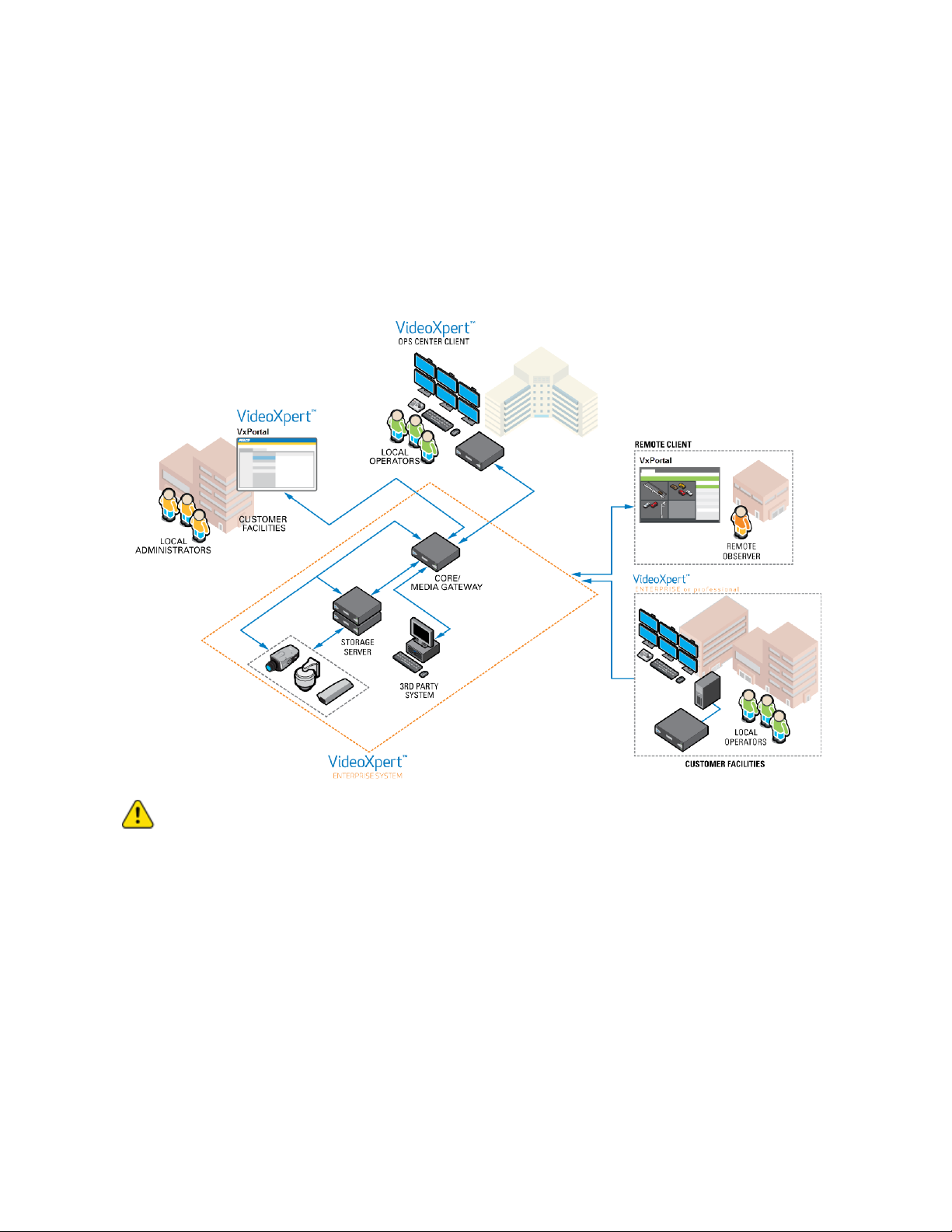
Understanding the VideoXpert® Enterprise System
VideoXpert is a video management solution designed to fit surveillance operations of any size. Whether
your operation has 100 cameras or 10,000, VideoXpert presents a solution to display, record, and
manage your video resources. But VideoXpert Enterprise is more than a VMS. It is an enterprise-level
video and data management solution designed to combine input from multiple systems, for a cohesive,
real-time understanding of events taking place in your environment.
Action:Prior to obtaining a quote for or purchasing a system, contact a Pelco Technical Sales
Engineer to validate your system configuration.
C5673M-L | 03/22 4
Page 5

VideoXpert® Enterprise v 3.16 System DesignGuide
Scoping System Licenses
VideoXpert is licensed for the system, for upgrades, and by channel—the video streams you view and
record. It comes with one (1) license to start. The demo license provides unlimited channels that are
active for a period of 60 days. These are active only the first time you install the software, or if the
software was pre-installed, the first time you start up the system. In order for the system to function
beyond the evaluation period, add the appropriate quantity of licenses to the system.
Action:Ensure that you have enough licenses. See the current version of the VideoXpert
Enterprise Product Specification for available SKUs. Contact a Pelco Sales Representative for
more information.
C5673M-L | 03/22 5
Page 6

VideoXpert® Enterprise v 3.16 System DesignGuide
Planning for Device Discovery
When adding devices to VideoXpert, the system issues a discovery message and then listens for devices
for up to five minutes. Using the discovery process, VideoXpert adds your VideoXpert devices, including
Pelco cameras and many third-party cameras. You must then manually commission the devices.
Action:Ensure that there are enough licenses for all of the devices on the system, and ensure that
there will be enough bandwidth available to perform Device Discovery without interfering with
system operation.
C5673M-L | 03/22 6
Page 7

VideoXpert® Enterprise v 3.16 System DesignGuide
Planning for FISMA/NISTCompliance
VideoXpert is compatible with current FISMA/NIST requirements. If your organization must comply with
these requirements, establish a Risk Management Framework which includes:
l
Categorizing the system
l
Selecting security controls
l
Implementing security controls
l
Assessing the system
l
Authorizing the system
l
Performing continuous monitoring
The current version of the VideoXpert Configuration Guide for FISMA/NIST Environments includes
configuration guidance and information needed to build a system documentation package for security
control assessments. Specifically, the guide will help organizations documenting the system through the
RMF process with information about how to categorize the system, which NIST-based security controls
are applicable, and how VideoXpert Enterprise implements NIST-based security controls. Testing of
these controls has also been performed by Pelco with VideoXpert Enterprise installed on a FISMA
representative system to ensure functionality under a secure configuration with DISA STIG rules applied.
Note:NIST security control baseline has many allowances for organization-defined settings.
While the VideoXpert Configuration Guide for FISMA/NIST Environments describes an RMFfriendly implementation for Pelco VideoXpert including NIST security controls and DISA STIG
rules, it might not precisely match your organizationally-defined settings.
Action:To configure your system for FISMA/NISTcompliance, contact Pelco Professional
Services to obtain the VideoXpert Configuration Guide for FISMA/NIST Environments.
C5673M-L | 03/22 7
Page 8

VideoXpert® Enterprise v 3.16 System DesignGuide
Selecting Servers
VideoXpert requires both Core and Media Gateway servers. Although you can leverage separate Core
and Media Gateway servers for systems of sufficient scale, most systems can easily support servers
running both the Core and Media Gateway (CMG) services. A single CMG server provides the complete
range of VideoXpert functionality that you would expect for systems with fewer than 2000 cameras and
100 simultaneous users.
However, for environments that are especially large, require exceptional redundancy, or incorporate a
high number of low bandwidth and aggregated users, you might install individual Core and Media
Gateway servers.
Action:Determine whether to use a CMG or separate VideoXpert Core server(s) and Media
Gateway server(s) based on the number of cameras and users on your system. See the following
sections for details.
Notice: Mainstream support through Microsoft for the Windows Server 2012 operating system
ended October 2018. Beginning October 2022, Pelco will no longer provide support for future
major software updates on this operating system. To prevent support disruption and continue to
take advantage of future updates, Pelco recommends that you purchase new servers with, or
upgrade the operating system of existing servers, to Windows Server 2016 or newer. For
information on upgrade options please contact Microsoft Corporation.
Choosing to Use One or More VideoXpert Core(s)
VideoXpert Core is the heart of the VideoXpert System, it maintains the database of cameras, recording
devices, users, and permissions. Core works with VxToolbox, from which you can configure and manage
the system. Through VxToolbox, you can administer user accounts and permissions, determining the
system functions and devices users can access. You can create and assign “tags” to quickly organize
cameras and devices within the system. You can also configure and respond to events within the system.
Choosing to Use One or More VideoXpert Media Gateway(s)
The VideoXpert Media Gateway routes video traffic to appropriate users as requested. The Media
Gateway:
l
Routes the video to the workstation in a multicast environment
l
Accesses the video in a unicast environment
l
Transcodes the video for low-bandwidth connected VxOpsCenter clients
You can set the communication method, unicast or multicast, from the Video Source to the Media
Gateway, and from the Media Gateway to the client. The media gateway is capable of transcasting
multicast from the source to unicast for the client, and from unicast to multicast.
Like Core servers, Media Gateways can be added to VideoXpert modularly. You can add Media
Gateways to the system as the media delivery needs increase.
C5673M-L | 03/22 8
Page 9
VideoXpert® Enterprise v 3.16 System DesignGuide
Planning to Use VideoXpert Aggregation
VideoXpert Enterprise with Aggregation allows for expansion at any level of your security environment.
Your system begins with a single server running Core and Media Gateway software. Your system can
use dedicated VxOpsCenter Clients to view live and recorded video, or it can use VxPortal, which fully
utilizes HTML5 browser technology to deliver a similarly rich experience with no client software required.
As your surveillance needs grow, you can add servers to expand modularly within a single environment,
or you can aggregate multiple VideoXpert Enterprise systems to provide a single point of access for
distributed video management networks.
Caution:Although VideoXpert Professional and VideoXpert Enterprise systems can be
aggregated into the same Enterprise system, it is not recommended that you have crossaggregation between multiple systems simultaneously.
Growing theVideoXpertSystem
If your system grows to support additional users, cameras, or sites, or you just want to provide
redundancy within your VideoXpert system, you can separate your VideoXpert Core and Media Gateway
servers, and increase system capacity by clustering servers. If you are using aggregation, you can also
aggregate other VideoXpert systems.
Consider using separate Core and Media Gateway servers when:
l
There is a high number of simultaneous users.
l
The system must scale to a high number of cameras and users.
l
You have high expectations for availability and redundancy.
C5673M-L | 03/22 9
Page 10
VideoXpert® Enterprise v 3.16 System DesignGuide
The table below lists typical deployment scenarios, with the maximum number of cameras and
concurrent system users for each deployment; these numbers represent the limits at which the system
becomes unusable (high latency in control requests).
Deployment Cameras Users Availability Additional Requirements
Single CMG 2500 100 Not fault tolerant N/A
Dual CMG 2500 100 Active-Active single
failover
Dual CMG (NSVR) 7500 400 Hot-standby failover N/A
Triple CMG 10000 500 Active-Active single
failover
Single Core/ Gateway 3000 200 Not Fault Tolerant N/A
Multi-Core / Gateway >10000 >500 High Availability Independent load balancer
The table presents absolute maximums for VideoXpert deployment scenarios. Your experience might
differ based on your network configuration, network equipment, average video bitrates, and other criteria.
Action:Build the system with at least 10% additional capacity (in terms of cameras, users, or
preferably both), to ensure that the system is responsive and has additional capacity to take on
new users or cameras. When planning a VideoXpert deployment, contact Pelco to ensure that the
system has the capacity to support your environment and needs.
N/A
N/A
Using Active-Active Failover (Single CMG vs Multi-CMG Environments)
A single CMG can host nearly 2500 cameras and 100 concurrent users, but the system is not fault
tolerant; anything that could bring down the server will interrupt access to VideoXpert.
Action: Pelco recommends that if video is mission critical to the business, build a system with at
least two CMG servers.
Clustering Core Servers
In your VideoXpert environment, Core or CMG servers host the database. Clustering your Core or CMG
servers provides redundancy and enables VideoXpert to scale.
In a clustered environment, each Core or CMG server in the cluster hosts a complete copy of the
VideoXpert database.
In addition, you can install a copy of just the database on a server.
Note: VideoXpert itself performs all of the cluster configuration automatically during the setup
process. If configuring a system containing more than three servers, contact a Pelco Sales
Representatives or a Pelco Technical Sales Engineer.
Within each Core/CMG cluster, one server acts as the primary and the other servers operate as
secondaries. The primary server processes all write operations and pushes data to the secondaries.
Secondary servers replicate the primary server’s database asynchronously.
C5673M-L | 03/22 10
Page 11

VideoXpert® Enterprise v 3.16 System DesignGuide
l
If you have two servers and one is unavailable, there is no loss of functionality.
l
If you have three servers and one is unavailable, there is no loss of functionality.
l
If you have three servers and two are unavailable, the available server is put into a read-only
state.
In a read-only state, users can still call up video, but would be unable to apply bookmarks, export
investigations, apply tags, and perform other similar operations within the system.
Working with Clusters
A clustered environment requires at least two VideoXpert Core, Media Gateway, or CMGservers.
l
Cores and Media Gateways must be on the same VLAN. They must also have static
IPaddresses, and these IP addresses must be different from each other.
l
Traffic will be managed by a single Core; if that Core fails, another Core will perform the
management tasks. Other tasks, such as export processing, are shared among all Cores.
l
A single Media Gateway will receive streaming requests, but will redirect streaming to other Media
Gateways to balance the load.
l
The Media Gateway trans-casts to suit the network topology and needs. While the system is
configured to get multicast streams from sources and to issue multicast streams to clients, you
can select the appropriate communication method both from sources to the Media Gateway and
from theMedia Gateway to clients. The network topology and need for users to access sources
simultaneously will inform your choice.
Use VxToolbox to configure clusters. See the current version of the VideoXpert® Toolbox Operations
Manual section titled Adding Systems.
Aggregating Systems
VideoXpert Enterprise with aggregation includes an aggregation server, through which you can provide
centralized access to a series of VideoXpert member—VideoXpert Professional and/or VideoXpert
Enterprise—systems. Through the VideoXpert Enterprise server acting as the aggregation system, you
can access and control settings and video for distributed VideoXpert systems.
When adding a member to the aggregation server, you will select your connection speed to the
aggregation server. Your connection speed determines both the performance of video within the
VideoXpert environment hosting the aggregation server and the number of video streams you can
reasonably expect to get simultaneously from the aggregated site.
At present, you cannot change settings for aggregated systems from the VideoXpert instance hosting the
aggregation server. You must change settings for member systems from the member itself.
The aggregation server does not inherit permissions, roles, or users from aggregated members. If
aggregating a VideoXpert Enterprise environment containing roles with restricted permissions, you must
re-create these roles and permissions with resource restrictions with the VideoXpert System acting as
the aggregation server.
Using LDAP Authentication
You can configure VideoXpert to validate user credentials from an LDAP server. While the system can
validate credentials over LDAP, you must create corresponding user IDs and roles within the VideoXpert
database against which to validate the credentials. These IDs and roles must match the IDs and Groups
in the LDAP directory exactly (including capitalization) in order for the authentication to pass through.
Using the LDAP interface DOES NOT alter the schema of the LDAP directory, so all permissions to the
VideoXpert system(s) must be defined in the VideoXpert system
C5673M-L | 03/22 11
Page 12

VideoXpert® Enterprise v 3.16 System DesignGuide
You can select the authentication method and parameters used.
l
VideoXpert Authentication
When using VideoXpert Authentication, you can set passwords to expire at specific intervals, or to
never expire.
l
LDAP authentication using simple bind authentication
When using LDAP authentication with simple bind, you can set passwords to expire at specific
intervals, or to never expire.
l
LDAP authentication using two-stage binding
When using LDAPauthentication with two-stage binding, you can set passwords to expire at
specific intervals, or to never expire.
l
(Optional) If you select LDAP authentication, you can also retrieve users and roles from LDAP
l
LDAPauthentication using single sign-on (SSO)
–
SSO allows users to log in to multiple systems using a single set of login credentials.
–
SSOcan be used with either Single-Stage or Two-Stage binding, and can be used with the
Synchronize Users and Roles From LDAP option.
–
SSOrequires valid certificates; each user must have a valid certificate that the system can
access.
–
When using LDAPauthentication with SSO, you cannot set passwords to expire. Password
expiration is controlled by the LDAP database policies.
Note:If VxOpsCenter is running on the same server as the VxPro or Core system, SSOwill not be
available. This is due to MSWindows limitations.
Planning for Multi-System Access
You can design the VideoXpert system to run using Single Server Access mode or Multi-Server Access
(MSA) mode. MSA mode enables access to multiple stand-alone VideoXpert systems simultaneously.
When the system is in MSA mode, and Multi-System Access opens without initial credentials is selected
in VxToolbox, users can sign-in to VxOpsCenter without signing-in to a specific system. Credentials will
be required when you select a VXSystem.
Action:Not all integration plugins function correctly when using MSA mode. If you are connecting
to a number of systems that all have Access Control or the VideoXpert Plates ALPR plugin, the
plugins for each of the systems can only connect to one of the third-party systems at a time. The
plugin must be manually reconfigured to connect to the other integration site.
Action:When defining the system connections in the VxOpsCenter client software, you can finetune the maximum network bandwidth to allow from the system. This will ensure that the video
streams to the workstation have the best resolution and image rate possible without oversaturating the network link(s) between the system and the user workstation.
Action:When planning to use MSAmode, ensure that the same user ID and passwords exist and
exactly match on all of the different systems. When using MSA mode, Pelco recommends that you
use LDAPto synchronize users and roles to each VXsystem. This will ensure that the username
and passwords match.
C5673M-L | 03/22 12
Page 13
VideoXpert® Enterprise v 3.16 System DesignGuide
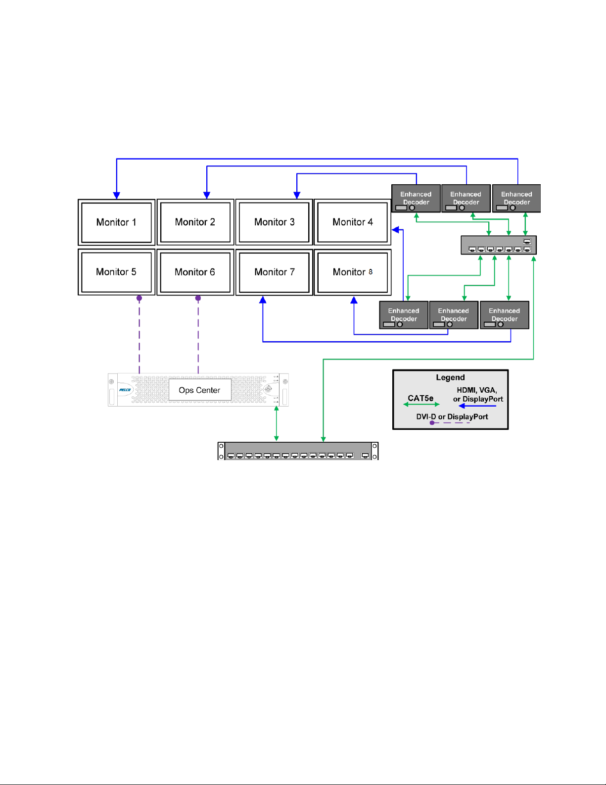
Understanding Operator Workspace Topology
The VxOpsCenter, running on an 8-monitor rackmount Workstation, supports up to eight monitors: two
connected directly to the Workstation, and the other six driven independently by Enhanced Decoders.
The Enhanced Decoders enable each monitor connected through a workstation to display up to 25 video
streams while maintaining a seamless user experience.
Enhanced Decoder-driven monitors operate just like native monitors; users can move windows across
monitors seamlessly. But, when the user requests a video stream or plugin, the Enhanced Decoder
communicates directly with VideoXpert servers to get and decode video. This enables operators to
maximize the display-capabilities of the VxOpsCenter without complicating the user experience.
Because the Enhanced Decoders do not run the VxOpsCenter application themselves, you might
experience better performance in quantity and responsiveness of HD streams on decoder-driven
monitors, instead of directly-connected monitors.
VxOpsCenter also supports Shared Display mode which provides monitor-wall functionality for a VX
Workstation or a Shared Display Decoder. Monitor walls are specific groups of monitors that are
frequently viewed or used together. A monitor wall does not require an 8-monitor workstation, and it can
be scaled as large as needed using configured monitor numbers. (Monitor numbers are configured in
VxOpsCenter.) Users can send tabs and video to the shared display and control the shared display
remotely. In order to connect to the VXSystem from VxOpsCenter, the user must have permissions that
allows the user to add monitors to the system.
If you require additional monitors on a monitor wall, Shared Display Decoders can be used in
combination with Enhanced Decoders to create a complete monitor wall experience.
C5673M-L | 03/22 13
Page 14

VideoXpert® Enterprise v 3.16 System DesignGuide
Selecting Recorders
VideoXpert supports multiple recording platforms. In general, traffic and video delivery operates much
the same using any of the available recording platforms. If building a new system, you would typically use
VxStorage E-Series, VxStorage T-Series, and VXS5300 recorders; if migrating from an existing Endura
system, you can use NSM5200 and NSM5300 servers as recorders.
Action:Determine the recorders you will need for your system.
Using VideoXpert Storage (VxStorage) for Recording
VxStorage is a RAID 6, dual power supply, high-availability recording software platform that captures
recorded video for your VideoXpert system. The VxStorage E-Series, VxStorage T-Series, and VXS5300
have the following features:
l
Through the user of camera drivers, the VxStorage can support most camera models from most
camera vendors.
l
VxStorage supports hot-standby failover configurations so that it can be configured for highavailability.
l
VxStorage has a flexible scheduling engine which allows you to extend the retention of data on
the system without sacrificing video quality.
l
On the VxStorageE-Series and VxStorage T-Series, the operating system is contained on an dual
SSD RAID 1 array; hard drives belonging to the RAID array are hot-swappable.
l
The VxStorage E-Series, VxStorage T-Series, and VXS5300 servers come with redundant power
supplies.
l
Server management uses the embedded iDRAC port which provides out-of-band diagnostics and
remote access to the server OS in the event of a failure.
l
VxStorage natively supports IP cameras via ONVIF S, G, Q, and T, and via native driver
packages.
You can configure storage through VxToolbox, making it easy to set recording schedules and assign
cameras to your storage servers. Storage supports motion, alarm, and bump-on-alarm style recording,
so you can always capture events relevant to your environment at high quality. You can set different
retention times per camera or camera group. Storage also supports redundant recording by assigning
cameras to multiple recorders, ensuring that VideoXpert continues recording video even if a single
storage server falls offline.
Using VSM, NSM5200, and NSM5300 Servers as VideoXpert Recorders
VideoXpert supports VSM, NSM5200, and NSM5300 servers as VideoXpert Recorders. NSM5200 and
NSM5300 servers provide migration paths to VideoXpert; both can operate as recorders within
VideoXpert while continuing to support their respective Endura environments.
The VSM, NSM5200, and NSM5300 recorders can be configured as a pool, where one unit acts as the
pool manager and the other units will take the camera assignments from the pool manager. This also
allows for automatic camera redistribution across the remaining pool members, in the event that one of
the pool members fails. The manager role is handled as an election process within the pool and will be
reassigned to another pool member if the pool manager fails.
C5673M-L | 03/22 14
Page 15

VideoXpert® Enterprise v 3.16 System DesignGuide
Planning for Recording
Recorder types and the settings for recordings can vary widely as VideoXpert systems expand and
change. Devices assigned to recorders will record based on the schedule and recording triggers you
configure through VxToolbox.
Factors to consider when planning for recording include:
l
The number and type of data sources (video, audio, PTZ vs. fixed, etc.) that will be added to a
recorder
l
The recording behaviors (triggers)
l
The data source recording schedules
l
The global maximum retention period of recordings (The retention period for individual devices
must be shorter than the global retention period.)
l
The transmission method (multicast or unicast)
l
The stream(s) to record (primary, secondary, and/or tertiary)
l
Whether the system uses motion recording
l
Whether the system uses bump-on-alarm recording
l
Whether and how many data sources are using auto-backfill of recording gaps
l
The maximum bitrate of recordings
l
How many bookmarks are expected to be stored, the standard retention limit of unlocked
bookmarks, and the expected retention of locked bookmarks
Action:Ensure that you have enough recorders (standard and failover), recording space (per
recorder and system-wide), and appropriate network capacity to support the likely storage
requirements and network traffic.
Correlating Recording Storage Platforms and Their Requirements
VideoXpert supports the recording platforms identified in Table 1: Recording platforms.
Table 1: Recording platforms
NSM5300
(2.4.3 or
later)
VxPortal /
Pelco
Utilities
250 Mbps
in; 32
streams
out (per
pool)
Parameter
Maximum
VxStorage
T-Series
144TB 288 TB 48 TB 48 TB 48 TB
VxStorage
E-Series
VXS5300 VSM
capacity
RAIDlevel RAID6 RAID6 RAID 6 RAID6 RAID 6
Configure using VxPortal VxPortal VxPortal VxPortal / Pelco
Utilities
Bandwidth
1 Gb: 700 Mbps
in; 175 Mbps out
10 Gb: 1000
Mbps; 175 Mbps
out
1 Gb: 700 Mbps
in; 175 Mbps out
10 Gb: 2500
Mbps; 175 Mbps
out
450 Mbps in;
175 Mbps out
250 Mbps in; 32
streams out (per
pool)
C5673M-L | 03/22 15
Page 16

VideoXpert® Enterprise v 3.16 System DesignGuide
Note:Optera cameras or cameras supporting high framerates and resolutions require an
increased amount of storage. This is mostly due to increased bitrates; in some cases, increased
processing load might also become a factor.
Understanding Camera Support
Different VideoXpert systems support different cameras, as shown in Cameras supported per
VideoXpert System.
Table 2: Cameras supported per VideoXpert System
Camera VideoXpert Storage VSM/NSM
Optera Yes Yes
1
Pelco Smart Analytic enabled Yes No
Other legacy Pelco Yes Yes
ONVIF-compliant Profile S No
Native APIsupport Axis, Hikvision, Panasonic, Vivotek, etc. No
1
Optera is supported on the VSM/NSM however the camera is limited to Tile mode. The Panomersive
modes are not available.
Planning for Camera SDCard Data Retrieval
Some cameras have SD card data retrieval capabilities to populate the recorded video. Using this
capability can cause extra network traffic due to the SD card polling and the recorder replenishment from
the SD card to the recorder(s).
Action:Consider this capability when devising the recording schedule(s), and accommodate for
the potential extra network bandwidth needed.
Planning for Auto-Backfill
For cameras that have local recordings, you can enable Auto-backfill recording gaps using on-camera
storage. When selected, if there is a gap in recording of a camera (an edge device), the recorder will
query the camera for recordings, and automatically download video and audio (if present) to fill the gap.
You can also adjust the following settings:
l
The number of cameras from which data is downloaded at one time
Downloading from more cameras uses more bandwidth, which will slow the data transmission
rate.
l
A time-interval to apply if edge devices (cameras) and the recorder lose communication
The VXSystem will attempt to connect to the edge device again at the time-interval specified in
this field.
l
The number of attempts to reconnect if edge devices and the recorder lost communication.
l
If available, the maximum bitrate at which to download data.
Action:Determine the number of cameras that will use Auto-Backfill, the time-intervals to apply
when reconnection is necessary, the number of attempts to reconnect, and the maximum bitrate
for each download. Use this information to ensure you have enough network bandwidth to
accommodate the reconnection attempts and downloads.
C5673M-L | 03/22 16
Page 17

VideoXpert® Enterprise v 3.16 System DesignGuide
Planning for Recording Schedule Capabilities
The primary recording schemes used by VideoXpert are:
l
Continuous recording can be performed at full or reduced frame rates.
l
Event-triggered recording (including alarm, analytics, and motion detection events) is performed
at full frame rate.
l
Bump-on-alarm is a type of continuous recording during which the system records reduced frame
rate (I-Frame only) video during normal situations, and records full frame rate video during an
alarm or event.
l
In VxToolbox, administrators reduce the frame rate of previously recorded video after a specified
number of days, resulting in increased retention time and storage cost savings. To use this
feature, see instructions in the current version of the VxToolbox OperationsManual.
Action:Full frame-rate recordings will consume more storage than reduced frame rate recordings.
Ensure that your system has enough storage to accommodate the expected recording types.
Using Volumes and Volume Groups
You can organize your device video storage by creating and managing Volumes and Volume Groups.
l
A volume is a logical directory in which you want to store video.
l
A volume group is a group of volumes to which cameras are assigned and distributed. You can
use volume groups to:
–
Separate types of storage (like internal vs. external).
–
Set different retention parameters for different sets of drives.
–
Write video to more than one volume. When all volumes are full, the system will overwrite
volume containing the oldest stored video.
l
The system ships with a volume group called Default Volume Group. You can rename or delete
this volume group.
l
An archive volume group is a volume group to which the recorder will move the oldest video from
the other volume groups, instead of deleting the oldest video. See Using External NAS Storage
(Archive Volume Groups) for more information about the archive volume group.
Action:To use volumes and volume groups, determine which cameras will be assigned to each,
on which recorder the volumes and volume groups will reside, and where the archive volume group
will reside. Ensure there is adequate storage and network bandwidth to support their use.
Using External NAS Storage (Archive Volume Groups)
By connecting an external volume (network storage/NAS) to your system, you can extend your retention
time for VideoXpert Storage recorders. When your VideoXpert Storage recorder achieves its maximum
capacity and would normally begin to delete the oldest video, it will send video over to the NAS instead.
Video will still adhere to retention parameters, even when moved over to external storage. The
experience in accessing video is the same, whether a recording is served from a the VxStorage recorder
or an external server.
Action:As video transfers from a VxStorage recorder to an external storage server, bandwidth of
your incoming cameras is equal to the bandwidth out to external storage. When using external
storage, plan storage distribution to ensure bandwidth availability for incoming cameras, storage
overflow, and user impact in viewing recorded video.
C5673M-L | 03/22 17
Page 18

VideoXpert® Enterprise v 3.16 System DesignGuide
Action: While each VxStorage recorder can only have a single archive group, multiple VxStorage
recorders can use the same NAS server. In this case each VxStorage recorder must point to a
different path/folder on the NAS server; pointing multiple VxStorage recorders to the same archive
group network path will cause video to expire earlier than expected and without warning.
Using VSM and NSM5300 Models as VideoXpert Recorders
Through VxToolbox, you can set camera associations and recording schedules; however, you must
configure other aspects of your recording devices through other interfaces. Configure storage pools
through the VSM/NSM5300 Web interface. Configure recording schedules through Pelco Utilities.
Planning for Redundant Recording
Redundant recording can be configured to perform in the following ways:
l
Two recorders recording the primary stream
l
Two recorders recording the same camera with one recording the primary stream and the other
recording an alternate, lower-quality stream
Recordings do not have to be the same size/retention unless those are part of the end-user's standards.
Plan for the following network considerations when configuring redundant recording:
l
Multicast recording of the streams will allow for only a single stream coming out of the camera, no
matter how many recorders are recording the stream.
l
Unicast recording of the cameras will have implications in that most cameras can only push out 24 copies of the stream; if two streams are in use by recorders, then there might not be another
stream available for live viewing.
l
Double the number of network ports you would otherwise need for recorder connection.
l
In Unicast-recorded networks, the bandwidth handled by the uplinks between the switches and
the switch backplanes will be doubled; this could result in resource over-allocation or
recording/viewing failures.
l
Unicast recording could result in the need to create LACP teamed network trunk uplinks, or
necessitate replacement of the switches/switchports with 10Gig inter-switch network ports.
When planning HVAC and UPS for rendundant recording:
l
Double the number of power plugs you would otherwise need.
l
Plan for additional BTU mitigation.
l
Double the number of network ports you would otherwise need for recorders.
l
Include enough UPS battery capacity to maintain the desired power-outage run time for the
system including the additional recorder(s) power load.
Configuring VideoXpert Storage Failover Recording
By putting VxStorage units in failover mode, you can assign VxStorage models to act as hot-standbys for
live recorders and ensure uninterrupted recording when active recorders fail. Pelco recommends that
you use this feature to implement a failover strategy that ensures full time recording and video availability
in your environment in the event of possible network, power, or hardware failures.
A single designated failover recorder can monitor up to eight active recorders. When a recorder is in
failover mode, if there is a failure in any of the recorders that the failover unit is assigned to monitor, the
C5673M-L | 03/22 18
Page 19

VideoXpert® Enterprise v 3.16 System DesignGuide
failover unit will take over and continue recording the camera groups and schedules previously belonging
to the failed recorder.
Failover recording does not ensure access to historical data from failed recorders; it only ensures
continued recording. If you want to maintain uninterrupted access to recorded video, even when a
recorder fails, then record cameras redundantly across multiple recorders.
One or more failover recorders can be added to a Failover Group to monitor one or more other recorders.
If a unit fails, one of the recorders in the failover group will take over recording of the cameras and
schedules belonging to the failed unit(s). The failover recorder(s) will record cameras from multiple failed
recorders simultaneously, up to the maximum capability of the failover recorder(s).
The failover recorder(s) do not need to be of the same capacity as the production units, but they must be
sized to accommodate the video retention that would be needed until the production recorder can be
brought back online.
Action: Ensure that you have enough standby VxStorage units to support your failover
requirements.
C5673M-L | 03/22 19
Page 20

VideoXpert® Enterprise v 3.16 System DesignGuide
Planning a BackupStrategy for Recorder Database Entries
A system backup contains the system database. Backups do not capture exported video or any settings
that you changed outside of VxToolbox (for example: changes made directly to configuration scripts).
The speed of each backup depends on the size of the VideoXpert database, network bandwidth, and
other variables.
VideoXpert Storage takes database recovery points daily, and stores these points for ten days. You can
also initiate a manual backup.
Understanding VideoXpert Storage Failover and Redundant Recording
Recorders are not part of the standard Core/CMG cluster. However, typical deployments should arrange
for some measure of redundancy to ensure that required streams and video never go unrecorded.
VideoXpert Storage (VxStorage)supports two methods for redundancy:
l
Redundant recording—assigning the same camera to multiple recorders, or setting the camera
primary stream to record on one recorder and the secondary or tertiary stream on another
recorder
l
Failover monitoring—assigning a recorder to act as a hot-standby for one or more recorders
Redundant recording is a quick way to ensure video uptime and redundancy, but requires an equal
amount of storage across each recorder set to record a stream.
Putting recorders in Failover mode allows you to assign them to monitor and act as a hot-standbys for
active recorders; if any of the active recorders fail, the failovers will record the camera groups and
schedules in place of the failed recorders ensuring nearly uninterrupted recording.
Note: During a failover, you might experience a recording gap of up to 30 seconds.
Selecting Independent Backup Storage
For any system with more than one VideoXpert Core, you must backup to a network location. The
network location must be accessible via a UNC path (for example:\\backupserver\backups). Local and
mapped network drives (S:\backups) are not supported for the backup process. Pelco recommends that
you store backups to a server independent of other VideoXpert hardware, preferably containing its own
RAID array, ensuring that your backups are safe from catastrophic failures.
Action:If your VideoXpert system has more than one Core, select one or more independent
servers for backup storage. Plan to accommodate network traffic for these servers.
C5673M-L | 03/22 20
Page 21

VideoXpert® Enterprise v 3.16 System DesignGuide
Evaluating Additional System Components
Depending on the shape and scale of your system, you might need one or more of the following
components.
Selecting a Load Balancer
For load balancing, you can use VideoXpert Internal Load Balancing or an external load balancer.
Using VideoXpert Internal Load Balancing
If VideoXpert internal load balancing is used, then the CMGs must be on the same VLAN. This is
because the high availability VIP is owned by the CMGs .
Using an External Load Balancer
For systems with more than three CMGs or multiple independent Core and Media Gateway servers, you
might need an external load balancer. The load balancer provides the virtual IP address used to target
clustered servers.
Your load balancer must meet the following requirements.
l
High-level requirements:
–
HTTP
–
HTTPS
–
websocket support
–
RTSP support; alternatively, support for raw TCP/IP connections
–
Support for multiple sets of backend servers; necessary if using separate Core and Media
Gateway servers
–
Support for application-level HTTP healthchecks
–
Support for application-level RTSP or TCP/IP health-checks
l
High availability requirement—Must be able to configure load balancer appliances such that if an
appliance becomes unavailable (for example:through power loss), the other appliance(s) can
assume functionality of the unavailable appliance.
l
Recommended Features:
–
Allow administrators to gracefully disable servers during upgrades
–
SSL offloading
Action:Select a load balancer that is appropriate for the size of your system. Contact Pelco
Professional Services for assistance.
Using a Network Time Protocol (NTP) Server
All servers in your VideoXpert system must reference a time server to ensure that all devices belonging
to the system use the same time. Time disparities may result in errors when recording and recalling
video.
l
Pelco recommends that you use an official NTP server or purchase and use a network clock to
keep your system synchronized.
C5673M-L | 03/22 21
Page 22

VideoXpert® Enterprise v 3.16 System DesignGuide
l
You can choose to use the VideoXpert Core cluster on your VideoXpert system as the
NTPserver, but doing so will allow the time of your system to drift significantly from the actual time
if there is no time source.
Action: Pelco strongly recommends that you have a dedicated NTP server for VideoXpert. Other
options include:network routers configured as NTP servers, an application like Nettime for internet
connected systems, and a GPS or cellular network time server device.
Selecting a DHCP Server
Pelco recommends that you use a DHCP server to assign and manage addresses for the devices within
your VideoXpert network, using one of the following:
l
Microsoft Windows with DHCPServer
l
DHCPservices on a network switch
l
A separate, dedicated DHCP server (for advanced installations with multiple ranges and a need to
edit address reservations.)
Action:Select an appropriate DHCPserver to accommodate the number of ranges on the
VideoXpert System and whether you will edit address reservations.
Supporting DNS
On systems that are connected to networks with DNS servers, the devices can resolve the hostnames of
the source devices, rather than just relying on the IP addresses. This is key for multiple NTP server
connectivity. Using DNS also provides the administrator the ability to:
l
Leverage the DNS system to create DHCP IP address reservations.
l
Resolve the name of the device using the IP addresses.
Designing Export Archive Storage
You can store exports in a network location on or off of the VideoXpert Core server. Storing exports off of
the Core ensures greater availability to exported video, especially in clustered environments. When
storing exports on the Cores in a clustered environment, exports are not shared among Cores; each
export is only stored on the Core server on which it was created. If the server storing an export fails,
users lose access to the exported video; if the server fails and you have to restore from a backup, you will
lose your exports on that Core server. Storing exports in a separate location ensures availability
independent of any individual Core server, and allows you to easily backup video exports at whatever
interval is most convenient for you.
You can either save exports to the default location or to another location. Any other location must be
defined in URIformat; it cannot use the local drive letter format. If export encryption is enabled, a
password is required for saving to the default location.
Action:Design an appropriate storage strategy that will ensure the availability of exports. Plan for
the amount of storage and the network traffic necessary to support the strategy.
C5673M-L | 03/22 22
Page 23

VideoXpert® Enterprise v 3.16 System DesignGuide
Understanding Network Operation Modes
Using Rendezvous Points (RP)
PIM-SM builds a shared multicast distribution tree within each domain, and the RP router is at the root of
this shared tree. Although you can physically locate the RP anywhere on the network, it must be as close
to the source as possible. Only one active RP router exists for a multicast group.
At the RP router, receivers meet new sources. Sources use the RP to identify themselves to other routers
on the network; receivers use the RP to learn about new sources.
The RP performs the following tasks:
l
Registers a source that wants to announce itself and send data to group members
l
Joins a receiver that wants to receive data for the group
l
Forwards data to group
Sample RProuter configuration is as follows:
ip multicast−routing
ip pim send−rp−announce loopback0 scope 16
ip pim send−rp−discovery scope 16
interface loopback0
ip address <address> <mask>
ip pim sparse−dense−mode
interface ethernet0
ip address <address> <mask>
ip pim sparse−dense−mode
interface serial0
ip address <address> <mask>
ip pim sparse−dense−mode
Using PIM Modes for Multicast Routing
Protocol Independent Multicast (PIM) routing operates in either Sparse Mode (SM), Dense Mode (DM),
or Sparse Dense Mode(SDM).
Action:Before selecting a PIM operating mode, consider the impact that protocol selection will
have on the network.
The following sections provide an overview of PIM modes and use considerations.
Using PIM Dense Mode (PIM-DM)
PIM-DM is easier to install than PIM-SM. The network engineer will enable PIM-DM on each network
router that is required to route multicast traffic. PIM-DM operates in what is referred to as a push model.
Traffic is initially flooded to all neighbors that have formed a PIM neighbor relationship. Downstream
routers will then determine if the traffic is necessary and either forward the traffic appropriately or send a
prune message to an upstream router to suppress the flow of multicast traffic. Keep in mind that although
the traffic has been suppressed, the (S,G) state is still maintained in the multicast routing table. One of
the major drawbacks to PIM-DM is that multicast routing switches that are not actively transmitting a
C5673M-L | 03/22 23
Page 24

VideoXpert® Enterprise v 3.16 System DesignGuide
multicast flow might still be required to maintain that state. Maintaining this state can lead to the
consumption of additional resources on the switch even though no active client on that router has
requested the multicast traffic. During the flood and prune cycle (S,G), states are flooded to every
multicast router on the network and every multicast router will maintain the (S,G) state as long as the
multicast source is actively transmitting. The resulting traffic flow for multicast will follow the shortest path
tree (SPT) from source to receiver.
l
Determine if the Layer 3 routing devices support state refresh. Because PIM-DM will flood
traffic throughout the network to build (S,G) states in each downstream multicast router, careful
consideration must be given to the support of state refresh. Multicast routing devices that support
state refresh will prevent periodic flooding. PIM-DM operates in a flood and prune cycle. The
multicast routing tree is flooded every three minutes and relies on pruning mechanisms to
determine whether or not downstream routers require the multicast traffic. Periodic flooding of the
network can be a major concern for networks for which bandwidth is limited. Layer 3 devices that
support state refresh prevent the countdown timer on the (S,G) entry from expiring. If the
countdown timer never expires, the multicast source will no longer flood the network periodically
after the initial flood cycle.
l
Determine the multicast table routing table entry limitations of each switch on the
network. There is a finite limit for each switch concerning the number of multicast routing table
entries the switch can handle. If the available multicast routing table entries are exhausted, further
entries might fail to be allocated to the table resulting in a multicast group that can no longer be
routed. As a network engineer, you must ensure that the switch that is being used is not exceeding
its capacity for the multicast routing tables. It is the responsibility of integrators or network
engineers to contact the switch manufacturer to assess the capabilities of the switch and any
limitations with respect to multicast routing table entries.
l
Select recommended network switches or test non-recommended switches. In addition to
the multicast routing table, a selected switch must be able to handle an adequate number of IGMP
entries. Switch manufacturers specify the number of IGMP entries a switch can handle. When
switches exceed these limits, they typically will either flood or block multicast traffic. Pelco
maintains a list of recommended switches that have been tested for their maximum recommended
IGMP entries. If an integrator or network engineer selects a switch that is not from the
recommended switch list, it is the responsibility of the integrator or network engineer to contact the
vendor to determine the IGMP limitations of the switch selected.
l
Verify network limitations associated with wireless connections. Due to the limited
bandwidth associated with wireless connections, PIM-DM might not be an appropriate selection.
The flood and prune cycle might result in a wireless network link that becomes saturated.
Using PIM Sparse Mode (PIM-SM)
While PIM Sparse Mode requires careful consideration during the design process, there are major
benefits associated with using PIM-SM as opposed to PIM-DM. Unlike PIM-DM, PIM-SM has a
dedicated RP to send messages to build both the shared (*,G) and source (S,G) sides of the tree. The
end result is that PIM-SM will not perform flood and prune cycles to build trees for forwarding multicast
traffic. When the multicast traffic is not flooded to all PIM-enabled devices, devices not in the path of
transmission will not maintain entries in the multicast routing table. This will result in lower utilization of
switch resources that are not in the SPT.
Due to the operation of PIM-SM, placement of the RP can be a critical decision in network design. If a
centralized RP is selected for all traffic in the network, that switch must be able to handle the appropriate
number of multicast routing table entries for all traffic traversing the network. As an alternative, you can
use multiple RPs that serve as candidates for multicast routing. Filtering can be implemented to distribute
the multicast routing load across multiple RPs. This type of application allows you to distribute the
C5673M-L | 03/22 24
Page 25

VideoXpert® Enterprise v 3.16 System DesignGuide
multicast routing load across multiple PIM-SM routers and, if designed properly, isolates multicast traffic
to intended segments of a network. For example, if a multicast recording network storage pool is
implemented and the RP also serves as the local designated router, multicast recorded traffic would use
its local designated router as the RP and isolate the majority of the multicast flows to the local router.
Since the SPT is local to the switch, multicast recording traffic would be contained within a segment of
the network.
In an implementation using PIM-SM, only the initial video packets are sent to the RP. If a single RP is
used in a network, after the encapsulated video in the register message is sent, all remaining video
packets use the SPT from source to destination.
An SPT threshold can be configured to force a multicast flow to bypass the SPT. Care should be taken if
SPT thresholds are to be modified.
If a single RP is used in PIM-SM, it is critical that the multicast routing switch have enough resources to
handle all (*,G) and (S,G) entries that will be created in the multicast routing table. Even though the traffic
is traversing the SPT, resources must be allocated to handle all existing multicast routing table entries,
and any processing of joins and prunes throughout the network. Packet replication, RPF recalculation,
state maintenance, and register processing all create memory and CPU loads on the RP. Depending on
the size of the network and scalability requirements, different Layer 3 devices might be selected as RP
based on their resources.
The default response of PIM on some switches is to fall back to PIM-DM in the event that a RP cannot be
found. Based upon the network topology this might or might not be a desired effect. Always take into
account the effect that reverting to PIM-DM might have on the network. This response is present on
Cisco systems.
Using Sparse-Dense Mode (PIM-SDM)
Some implementations of PIM simultaneously support Dense Mode for some multipoint groups and
Sparse Mode for others. This provides the regularity of flood/prune broadcasts in Dense mode and the
bandwidth savings of Sparse mode.
Using DVMRP for Multicast Routing
DVMRP is a routing protocol supporting multicast transmission. Stemming from Routing Information
Protocol (RIP) and used in the Internet multicast backbone (Mbone), DVMRP allows for tunneling
multicast messages within unicast packets. It also supports rate limiting and distribution control based on
destination address, and it is responsible for the following tasks:
l
Routes multicast datagrams
l
Periodically floods multicast traffic (similar to PIM-DM)
l
Allows use of non-multicast aware edge devices
Note: When choosing PIM-DM or DVMRP as a multicast routing protocol on systems that include
wireless devices or that require remote access to the system, understand that these protocols
have bandwidth limitations that are negatively affected by periodic flooding of data streams.
C5673M-L | 03/22 25
Page 26

VideoXpert® Enterprise v 3.16 System DesignGuide
Planning Network Traffic Flow
Command and control traffic (user actions within the system), occur over HTTP or HTTPS depending on
your system. You can configure workstations to operate over HTTP or HTTPS, and you can select the
port for communications with VideoXpert Servers. (For information on ports, see the section titled
Appendix B:NetworkProtocols and Ports Reference.)
Video is delivered to clients either via RTSP or RTP, depending on the Media Gateway Communication
method for which your system is configured. When configured for unicast delivery to clients, the Media
Gateway re-streams video to the client. When configured for multicast delivery to clients, video streams
directly from the camera, encoder, or RTSP source from which the stream is requested.
Addressing Traffic and System Limitations
VideoXpert systems are tested to determine how many users and cameras a system supports before
performance degrades significantly. The systems tested represented environments with strong network
connections using VSM models for storage. For purposes of performance tests, “users” are
simultaneous operators performing continuous, expected duties, including streaming video, receiving
events, controlling (PTZ) cameras, and exporting video.
Refer to the current version of the VideoXpert Enterprise Product Specification for details.
C5673M-L | 03/22 26
Page 27

VideoXpert® Enterprise v 3.16 System DesignGuide
For help determining the best system size and configuration to meet your needs, contact a Pelco Sales
Representative.
Addressing Client-Side Display Limitations
As aVxOpsCenter workstation uses an increasing amount of memory, users might experience “jittery”
mouse controls on decoder-driven monitors. This problem is most likely to occur if users are running
applications in tandem with the VxOpsCenter client, or is viewing a large number of Optera or HD
streams on locally-connected monitors.
Understanding Secondary and Tertiary Stream and Camera Settings
VxOpsCenter uses step-down behaviors when under heavy load. Optimal camera configuration ensures
that you always view the highest possible quality video and prevents the system from entering I-Frameonly or disconnection step-down scenarios.
l
Set secondary streams to 640 x 352 (or the corresponding 4:3 equivalent, depending on available
aspect ratios) at 5 images per second or lower to ensure secondary stream performance in a 4x4
layout.
l
For Optera cameras, set the I-Frame interval to 6 and use Smart Compression on the camera to
reduce the bandwidth being used. Optera cameras consume more system resources than other
cameras.
l
Set tertiary streams to the lowest resolution and frame rate that is acceptable to ensure tertiary
stream performance in high-density layouts and for use with low-bandwidth connections.
See the section titled Determining Streaming Delivery.
Understanding VxOpsCenter 6 x 6 and 8 x 8 Layout Requirements
Support for 6 x 6 (36 streams) and 8 x 8 (64 streams) layouts consumes a substantial amount of
resources on VxOpsCenter clients and enhanced decoders. To ensure that you do not overtax your
client system and enhanced decoders, Pelco recommends that you provide a secondary stream with a
maximum resolution of 640 x 480 and maximum framerate of 30 fps on the following Pelco-supplied
hardware:
l
For local viewing, a VxOpsCenter Desktop Workstation or a PC with comparable specifications is
required. See the current version of the VideoXpert Desktop Workstation Product Specification.
l
For viewing from a connected decoder, a VideoXpert Enhanced Decoder is required. See the
current version of the VideoXpert Shared Display Product Specification.
l
For viewing from a Shared Display (SDD), a VideoXpert Shared Display is required. See the
current version of the VideoXpert Shared Display Product Specification.
Streaming behavior can be unstable if the recommended stream configurations are not provided for each
viewable stream in a 6 x 6 or 8 x 8 layout. Typically, VxOpsCenter client will become very slow, possibly
unresponsive; in worst cases, the client might terminate due to lack of available resources.
Additional support information is as follows:
l
In setups with multiple monitors connected to the VxOpsCenter client PC, the maximum
supported number of concurrent streams is 64. This is only true if the secondary streams are
configured with the recommended maximum stream configuration of 640 x 480 at 30 fps.
l
No more that 128 streams are allowed on a single decoder instance. A decoder instance is an
enhanced decoder, shared display, or a local decoder on the VOpsCenter client PC.
C5673M-L | 03/22 27
Page 28

VideoXpert® Enterprise v 3.16 System DesignGuide
Caution
Pelco
:Although the hard limit for the number of streams per decoder instance is 128,
recommends that you do not exceed 64 streams. Doing so might have undesirable
behavior. The 128-stream limit is used as a buffer to allow functionality, such as stream
sequencing, to behave properly when streams are created and destroyed.
l
When dragging streams into cells, no more than 64 streams can be dragged at the same time.
l
VideoXpert Professional deployments on which VxOpsCenter clients are run from the same box
as the VxPro Server are not supported with 6 x 6 and 8 x 8 layouts; decoding and viewing 36-64
streams is resource-intensive and competes with VxPro Server for resources.
l
Due to the high resource demands of Optera and Evo cameras, Pelco recommends that you do
not stream Optera and Evo cameras above 5 x 5 layouts; the behavior is undefined if these
cameras are streamed in 6 x 6 or 8 x 8 layouts.
Determining Streaming Delivery
When the system is in Multicast mode, the stream comes directly from the camera. When the system is in
Unicast mode, stream delivery is largely the responsibility of the Media Gateway, and is dependent on
the communication method you select, your connection to the system, and the connection of aggregated
devices to the system. In general, you can receive streams identified in the table below.
Stream quality Factors
Primary Bandwidth > 100 Mbps; Cell size≥ 25% of layout
Secondary Cell size < 25% of layout; quality step-down when VxOpsCenter is under heavy
load
Tertiary Quality step down (from secondary stream) when VxOpsCenter is under heavy
load
I-Frame Only Quality step down (from tertiary stream) when VxOpsCenter is under heavy
load
MJPEG/H.264/H.265
VxOpsCenter:
- Client bandwidth > 5 mbs will support the full range of options, lower
connections will be forced to MJPEG.
- Aggregation connections with bandwidth >= 10 mbs will support the full range
of options, lower connections will be forced to MJPEG.
- PTZ Camera, when in MJPEG mode, will only support click-to-center. A
warning is given.
VxPortal: Same as VxOpsCenter, but without any warnings provided regarding
MJPEGlimitation.
See Appendix A:Video Streaming Diagrams for examples of streaming configurations and parameters.
Action:Because the system delivers secondary streams as a step-down adjustment, configure
secondary streams with reduced resolution and frame rate compared to the primary. Similarly,
because the system delivers tertiary streams as a step-down adjustment, configure tertiary
streams with reduced resolution and frame rate compared to the secondary.
C5673M-L | 03/22 28
Page 29

VideoXpert® Enterprise v 3.16 System DesignGuide
Making VxOpsCenter Streams Adjustments
By default, VxOpsCenter displays streams based on the size of the cells in a tab. Typically, cells that
represent 25% of a layout or more display full resolution, primary streams; cells smaller than 25% of a
layout deliver secondary streams. The 2x3 layout is also designed to show primary, full resolution
streams in all cells.
When the CPU load on the decoding device (Workstation, Shared Display Decoder, or Enhanced
Decoder) that displays the streams crosses the 75% threshold, VxOpsCenter will request lower-quality
streams in an attempt to reduce CPU load below 50% utilization. Stream quality is reduced from primary
to secondary, and secondary to I-Frame-only mode until the CPU load drops below 50%. If the reduction
in stream quality does not reduce the CPU load below the 50% threshold, VxOpsCenter will begin
disconnecting streams, citing limited CPU resources.
Planning for MJPEG Video Streaming
The system streams MJPEG video as described in Determining Streaming Delivery. MJPEG Video
includes the following limitations:
l
PTZ controls for MJPEG streams are limited to click-to-center controls.
l
MJPEG streams might not synchronize perfectly when in sync playback mode. This is due to the
nature of the MJPEG pull mechanism. You can still use the sync playback controls to manipulate
video, but synchronization might be noticeably affected.
l
When Media Gateway CPU utilization reaches its threshold, it will reject requests to transcode
new MJPEG streams.
Action:If cameras will be expected to return MJPEG video at greater than two I-Frames per
second, ensure that there is enough bandwidth on the system and that the Media Gateway(s) can
accommodate the MJPEG streams.
Planning for 4KSupport for Videos, Cameras, and Monitors
The VideoXpert system supports 4K monitors, 4K live and playback modes for cameras that support
streaming through ONVIF, and the ability to export recorded 4K segments.
Enhanced Decoders do not support 4Kvideo output to monitors. You can connect 4Kmonitors to
Enhanced Decoders, but the monitors will step down to show 1080p only.
Action:To support 4K video, cameras, and monitors, ensure that the VideoXpert system has
enough storage and network bandwidth to support the greater amount of data that will be stored
and streamed.
Planning for H.264 and H.265 Streaming
The system streams H.264 and H.265 video for users with connections greater than 10 Mbps, or
cameras belonging to aggregated sites with connection speeds greater than than 5 Mbps.
Note:VxPortal cannot consume H.265 streams directly, so uses MJPEG.
Cameras configured to use H.264 and H.265 streaming will consume more network and WANbandwidth
that MJPEG and other streaming methods.
Action:Determine how many devices will be using H.264 or H.265 streaming and ensure
adequate network and WANbandwidth.
C5673M-L | 03/22 29
Page 30

VideoXpert® Enterprise v 3.16 System DesignGuide
Planning to Use Additional Features
Planning for SNMP Monitoring
If you use anSNMPmanager to monitor the VideoXpert environment (native hardware or your own
hardware), you must monitor the same events as the VideoXpert Front PanelService. VideoXpert Front
Panel Service is a software utility that runs on Pelco hardware (native) that monitors the VideoXpert
services.
Pelco has other management information bases (MIBs) that can be used in SNMPmonitoring on the
VideoXpert system.
At a minimum, monitor and send traps for the following software services:
l
VideoXpert Core
l
VideoXpert Exports
l
VideoXpert Media Gateway
l
VideoXpert OpsCenter Communications
l
VideoXpert Storage
l
VideoXpertStorageDatabase
Pelco recommends that you monitor and send traps for the following hardware events:
l
Running software (executable name, path, and status)
l
Processor load
l
Storage/memory statistics
l
Hard disk failures
l
Power failures
l
System uptime
Action:Ensure that you have enough network bandwidth to support communication of
SNMPtraps you plan to send.
Planning to Use Maps
Maps imports and uses AutoCAD 2013 DWG files, raster maps (jpeg or png), and ESRI Street) maps,
allowing customers to use their pre-existing building maps with Maps in VideoXpert.
Action:If the system will use ESRIStreet files, ensure that each station that uses them has
internet access.
Planning to Use Integrations and Plugins
VideoXpert supports integrations both through VxOpsCenter and directly to VideoXpert Core.
Integrations through VxOpsCenter function as plugins—applications that a user can add to
VxOpsCenter—either operating in conjunction with or overlaying video. Integrations through Core
typically inject events into VideoXpert, extending the functionality of the system and issuing events to
VxOpsCenter users when the third-party system records them. Through integration, you can add incident
reporting, analytics, license plate recognition, and other features to VideoXpert. You can download
VideoXpert integrations and plugins from https://www.pelco.com/partners/technical-partners/.
C5673M-L | 03/22 30
Page 31

VideoXpert® Enterprise v 3.16 System DesignGuide
Pelco offers integration tools and software development kits (SDKs) to help you extend the functionality
of your VideoXpert system through the Pelco Developer Network at https://www.pelco.com/training-
support/developer-support/. Pelco’s Partner First site provides information about and access to a
number of ready-made integrations and plug-ins for VideoXpert.
Action: Find out storage and network requirements from the manufacturer of each plugin that you
will use. Ensure that the VideoXpert System has enough storage space and network bandwidth to
support all aspects of each plugin.
Action:Obtain the appropriate license(s)from Pelco or the third-party for each plugin that you use.
C5673M-L | 03/22 31
Page 32

VideoXpert® Enterprise v 3.16 System DesignGuide
Planning for Event Reporting, Logs, and Notifications
You can pull reports (in CSV format) containing events and configuration information to audit your
system and VideoXpert users. Reports requiring a start date and time include an event history; reports
that do not require a start date and time provide current configuration information only. System
Administrators can schedule automatic report generation in VxToolbox.
In addition, each VideoXpert product produces and stores its own logs, which roll over every 30 days.
You can use the logs to troubleshoot issues, or to help Pelco troubleshoot issues you might encounter in
the field.
In addition to the on-screen notifications, the VideoXpert system can be configured to send notifications
using SMSmessaging or via email. (SMS and email are not available on isolated network VideoXpert
systems.)This will increase network traffic based on the number and frequency of notifications that are
expected.
The following sections provide more information about events, reports, logs, and notifications.
Action:Ensure that you have enough storage and network bandwidth to support storing and
retrieving/accessing the reports and logs, and enough bandwidth to manage the network traffic
associated with notifications. For SMSnotifications, ensure network connections outside the
system through the Firewall. For email notification, ensure access to an internet-connected mail
server.
Understanding Event Types
Event types typically refer to who or what is the cause of an event, and do not necessarily determine the
report in which an event will appear:
l
Admin events typically occur at the administrative level.
l
Analytic events are the result of software analytics.
l
Client events are reported by the client.
l
External events are injected into the system by a third party.
l
Hardware events are the result of physical hardware issues and sensor readings.
l
System events are the result of normal operator actions.
l
Custom event types are configured through the Rules Engine in VxToolbox.
By default, events expire every 30 days. However, you can choose to keep events for up to 90 days, and
you can set different expiration periods for both events local to the system and events from aggregated
sites.
You can also set a maximum number of events; the default maximum is 10,000 events.
Using Reports
You can create and generate reports, and export them from the system. Reports are exported in CSV
format.
Report Types available in VxToolbox include:
l
Camera Report
l
Camera Role Access Report
l
Device Report
l
Event History
C5673M-L | 03/22 32
Page 33

VideoXpert® Enterprise v 3.16 System DesignGuide
l
Counting Lines Report
l
Recording Gap Report
l
Role Report
l
Storage Report
l
System Status Report
l
User Report
l
User Action Report
Create a new report template and edit the template details to include only the information needed. This
will affect the storage space necessary to accommodate the reports.
Locating Logs
Each VideoXpert product produces and stores logs to assist in troubleshooting. Logs are available in the
following locations:
l
Core—C:\ProgramData\Pelco\Core\logs
l
Media Gateway—C:\ProgramData\Pelco\Gateway\logs
l
VxStorage—C:\ProgramData\Pelco\Storage\logs
l
VxOpsCenter—C:\ProgramData\Pelco\OpsCenter\Logs; logs are available within the application
by navigating to About VxOpsCenter and clicking Get Logs.
Each of these location requires storage for the anticipated number and size of the logs.
Planning for Notifications
System notifications are delivered via a pop-up window on your VxOpsCenter Client. The System
Administrator can configure settings including:whether there is a pop-up banner associated with the
notification, whether the notifications require acknowledgment, and whether it will play a sound. The
configuration must define the individual groups that will be notified on each specific event type.
Notifications can also be sent using SMSmessaging or via email.
l
SMS messaging requires bandwidth and network traffic connectivity outside the system through
firewalls. To send SMS notifications, you must create a Twilio account for the system and then the
system Administrator must configure the notification in VxToolbox.
l
E-mail notification can only be used if there is a connection to an e-mail server via SMTP which
requires a connection to an internet-connected mail server. E-mail notifications are not available
for isolated network VX systems.
Configure event details and notifications to ensure that the right users are notified when the system
records a particular action or alarm. The way in which rules are configured determine how many
notifications are likely to be sent and how often.
C5673M-L | 03/22 33
Page 34

VideoXpert® Enterprise v 3.16 System DesignGuide
Appendix A:Video Streaming Diagrams
Multicast Recording, Multicast Viewingof a PelcoCamera
Live—Live video is authenticated by the CMG and streamed from the camera/network to the viewing
client and the VXS.
Playback—Playback is always unicast from theVXS.
*Bandwidth calculated is for one camera being viewed in a single screen on one monitor.VideoXpert
intelligently selects camera streams based on multi-screen configuration and client utilization.OPS
Viewing clients subscribe to camera source IGMP groups to view video in multicast.
C5673M-L | 03/22 34
Page 35

VideoXpert® Enterprise v 3.16 System DesignGuide
Unicast Recording, Multicast Viewing (With a VXSProxy)of a PelcoCamera
Live—Live video is authenticated by the CMG and streamed from the VXS to the viewing client. This is
the default on VX v 2.5, but is configurable onVXv 3.0 and later.
Playback—Playback is always unicast from theVXS.
*Bandwidth calculated is for one camera being viewed in a single screen on one monitor.VideoXpert
intelligently selects camera streams based on multi-screen configuration and client utilization.OPS
Viewing clients subscribe to camera source IGMP groups to view video in multicast.
C5673M-L | 03/22 35
Page 36

VideoXpert® Enterprise v 3.16 System DesignGuide
Unicast Recording, Multicast Viewingof a PelcoCamera
Live—Live video is authenticated by the CMG and streamed from the camera/network to the viewing
client. This is the default on VXv 3.0 and later, and can be changed so that theVXS provides the
multicast stream.
Playback—Playback is always unicast from theVXS.
*Bandwidth calculated is for one camera being viewed in a single screen on one monitor.VideoXpert
intelligently selects camera streams based on multi-screen configuration and client utilization.OPS
Viewing clients subscribe to camera source IGMP groups to view video in multicast.
C5673M-L | 03/22 36
Page 37

VideoXpert® Enterprise v 3.16 System DesignGuide
Unicast Recording, Multicast Viewing of an ONVIFCamera
Live—Some ONVIF cameras are re-streamed by the VXS to the OPSViewing client and authenticated
byVideoXpert Core; some are re-streamed by the Media Gateway to the viewing client. Features are
camera-dependent.
Playback—Playback is always unicast from theVXS.
*Bandwidth calculated is for one camera being viewed in a single screen on one monitor.VideoXpert
intelligently selects camera streams based on multi-screen configuration and client utilization.OPS
Viewing clients subscribe to camera source IGMP groups to view video in multicast.
C5673M-L | 03/22 37
Page 38

VideoXpert® Enterprise v 3.16 System DesignGuide
Unicast Recording, Unicast Viewingof a PelcoCamera
Live—Live video is authenticated by the CMG and streamed from the Media Gateway to the viewing
client. This is the default on VXv 3.0 and later, and can be changed so that theVXS provides the
multicast stream.
Playback—Playback is always unicast from theVXS.
*Bandwidth calculated is for one camera being viewed in a single screen on one monitor.VideoXpert
intelligently selects camera streams based on multi-screen configuration and client utilization.OPS
Viewing clients subscribe to camera source IGMP groups to view video in multicast.
C5673M-L | 03/22 38
Page 39

VideoXpert® Enterprise v 3.16 System DesignGuide
Appendix B:NetworkProtocols and Ports Reference
The tables below correspond to VideoXpert software components; in some cases, the same server can
host multiple components. The ports listed must be open to ensure VideoXpert functions properly.
Table 3: VideoXpert Core™ protocols and ports
Protocol Ports Service
TCP/HTTP 80 HTTP, used for camera configuration as necessary
TCP/HTTPS 443 HTTPS
UDP/SSDP 1900 SSDP discovery target on 239.255.255.250
UDP/WSD 3702 WS discovery
TCP/Hazelcast 6001 Hazelcast communications, before cluster
configuration
TCP/Hazelcast 6002 VxDatabase Hazelcast communications, before
cluster configuration
TCP/Postgres 15432 Database
TCP/Hazelcast SSL 16011 Hazelcast SSL communications, after cluster
configuration
TCP/Hazelcast 16012 VxDatabase Hazelcast TLS communications, after
cluster configuration
Table 4: VideoXpert Media Gateway™ protocols and ports
Protocol Ports Service
UDP/RTP/RTSP All When streaming Unicast from cameras, the Media
Gateway uses ports in the range 41950-65535 to
receive the data, but the client may request data on
any port. Multicast data will use the port configured
on the camera, thus all UDP ports must be
available.
TCP/RSTP 554 RTSP
TCP/HTTPS 5443 Internal API, HTTPS (MJPEG and other
communication)
TCP/Hazelcast 6002 Hazelcast communications, before cluster
configuration
TCP/HTTP 8090 Internal API, HTTPS (MJPEG) not used by the
system
TCP/Hazelcast SSL 16002 Hazelcast SSL communications, after cluster
configuration
C5673M-L | 03/22 39
Page 40

VideoXpert® Enterprise v 3.16 System DesignGuide
Table 5: VxStorage™ protocols and ports
Protocol Ports Service
UDP/SSDP 1900 SSDP discovery
TCP/RTSP 5544 RTSP video and audio command and control
TCP/Hazelcast 6003 Hazelcast communications
TCP port/ HTTP
9091 HTTP, APIcalls
TCP/HTTPS 9443 HTTPS, APIcalls
UDP/RTP 41950-65535 Receiving streamed video and audio
UDP/RTCP 41950-65535 Receiving media streams metadata
If recording in multicast mode, the required UDPport range is determined by the cameras.
Table 6: VSM / NSM5200 / NSM5300 Storage protocols and ports
Protocol Ports Service
TCP/SSH 22 SSH, remote shell connectivity
UDP/DHCP 68 DHCP Client
TCP/HTTP 80 HTTP, web access
UDP/SNMP 161 SNMP
UDP/SNMPTRAP 162 SNMP-trap
TCP/SMUX 199 SNMPmultiplexing service
TCP 1605 NSTERM Server
UDP 1781 NSTERM Search, recording services
UDP/UPnP 2900-2901 UPNP Discovery
TCP/HAL 4343 HAL
TCP 10000-10008 Private services for NSM5300/VSM
TCP 25556 DB Replication service for redundant recorders
UDP/UPnP 32768-61000 UPNP Communication
TCP/UPnP 49152 UPNP Communication
C5673M-L | 03/22 40
Page 41

VideoXpert® Enterprise v 3.16 System DesignGuide
Table 7: Enhanced Decoder protocols and ports
Protocol Ports Service
TCP/FTP 21 Used for firmware updates, snapshot downloads,
etc.
UDP 4500-4900 Unicast streaming via Windows host (not decoders)
TCP 43241 Proprietary control protocol
Enhanced decoders operate on Xubuntu 14.04 and communicate over the protocols identified in the
table above.
Table 8: Shared Display Decoder / VideoXpert Workstation protocol and ports
Protocol Ports Service
TCP/VNC 5900-5906 Allows the decoders to operate in concert with the
workstation as a single desktop/workspace
This is the normal port range for a workstation with 5 enhanced decoders. The actual range may vary.
The range can be confirmed on the workstation using the installed TightVNC Service Control Interface. If
no enhanced decoders are connected, these ports are not necessary.
Table 9: VxOpsCenter Client protocols and ports
Protocol Ports Service
TCP/FTP 21 Provides firmware updates to enhanced decoder,
downloads snapshots and logs from the enhanced
decoder
TCP/HTTPS 443 RESTAPI
TCP/RTSP 554 Video and audio command and control
UDP 4502-4900
1
Unicast streaming
TCP/RTSP 5544 Video and audio command and control
1
Unicast streaming previously used a port range of 4500-4600.
Table 10: Outgoing and general protocols and ports (for VxToolbox, VideoXpert Core, Media Gateway,
VxStorage, VideoXpert Professional, and for viewing clients)
Protocol Ports Service
TCP/FTP 21
TCP/HTTP 80
TCP/NTP 123
Time synchronization
TCP/HTTPS 443
TCP/RTSP 554
UDP/SSDP 1900
C5673M-L | 03/22 41
SSDPdiscovery
Page 42

VideoXpert® Enterprise v 3.16 System DesignGuide
Protocol Ports Service
UDP/WSD 3702 WS discovery
TCP/UDP/RDP 3389 Remote desktop
UDP 4500-4900 Unicast streaming via Enhanced Decoders
UDP 4502-4900
1
Unicast streaming via Windows host (not Enhanced
Decoders)
TCP/HTTPS 9443 Discovery of VxStorage
UDP/UPnP 49152 UPnPcommunication
TCP/UDP—RTP/
N/A Streaming and control
RTCP/RTSP
1
The VxOpsCenter and Shared Display unicast streaming previously used a port range of 4500-4600.
C5673M-L | 03/22 42
Page 43

VideoXpert® Enterprise v 3.16 System DesignGuide
Appendix C:Live Video Streaming Performance
The tables below provide VideoXpert users with expected camera streaming count performance, when
using various VideoXpert clients and decoders.
Testing was performed using these software versions:
l
VxOpsCenter v 3.11.0.330
l
VideoXpert Core v 3.11.0.106
l
VideoXpert Media Gateway v 3.11.0.55
Table 11: Camera configurations tested
Rate
Stream Name Resolution Framerate Bitrate GOP Encoding Profile
Control
Primary 1920 x 1080 30
Secondary 640 x 360 15
Optera 2048 x 11525 12
Optera, secondary 800 x 2680 6
4k 2560 x 1440 30
4k, secondary 1920 x 1080 15
5000
1150
16000
2000
8000
3850
30
15
12
6
30
15
264 high CBR
264 high CBR
264 high CBR
264 high CBR
264 high CBR
264 high CBR
Table 12: Products tested
Part Number Description
VX-A4-SDD Shared Display Decoder, Dell OptiPlex 7070 Micro 8 GB
VX-A5-SDD Shared Display Decoder, Dell OptiPlex 7080 Micro 16 GB
VX-WKST &VX-WKS Desktop Workstation, Dell OptiPlex XE3 SFF i7 16GB, NVIDIA T600
VX-RKWKS8T &VX-RKWKS8 Rackmount Workstation, Dell Precision 3930, i7 16GB, NVIDIA T600
(x2)
C5673M-L | 03/22 43
Page 44

VideoXpert® Enterprise v 3.16 System DesignGuide
Table 13: Results for VX-A4-SDD—Shared Display Decoder, Dell Optiplex 7070 Micro 8 GB and for VXA5-SDD—Shared Display Decoder, Dell Optiplex 7080 Micro 16 GB
Monitor Qty
and
Attachment
Monitor Resolution
Stream Quality
VX-A4-SDD
Maximum Camera
Count
1, direct 1080p Primary 6 6
Secondary 64 64
Optera, primary 2 2
Optera, secondary 19 34
4k, primary 6 6
4k, primary - H265 6 6
4k, secondary 23 34
2, direct 1080p Primary 12 12
Secondary 64 64
Optera, primary 4 4
Optera, secondary 19 64
4k, primary 8 12
4k, primary - H265 8 12
VX-A5-SDD
Maximum Camera
Count
4k, secondary 23 34
1, direct 4k Primary 6 6
Secondary 64 64
Optera, primary 2 2
Optera, secondary 24 64
4k, primary 6 6
4k, primary - H265 6 6
4k, secondary 23 35
The Maximum Camera Count is the maximum number of cameras that can be displayed on a defined
monitor configuration connected to the hardware tested, assuming that all cameras are set to the same
stream quality. Cameras can be distributed in any combination among all connected monitors. Different
display layouts will dynamically adjust to different stream qualities.
C5673M-L | 03/22 44
Page 45

VideoXpert® Enterprise v 3.16 System DesignGuide
Table 14: Results for VX-WKST and VX-WKS—Desktop Workstation, Dell OptiPlex XE3 SFF i7 16 GB,
NVIDIA T600
Monitor Qty and Attachment
Monitor Resolution
Stream Quality
Maximum Camera Count
1, direct 1080p Primary 12
Secondary 64
Optera, primary
Optera, secondary
4k, primary
4k, secondary
4, direct 1080p Primary
Secondary
Optera, primary
Optera, secondary
4k, primary
4k, secondary
2, direct 4k Primary
Secondary
4
45
12
64
16
64
4
45
10
64
12
64
Optera, primary
Optera, secondary
4k, primary
4k, secondary
4
45
12
64
The Maximum Camera Count is the maximum number of cameras that can be displayed on a defined
monitor configuration connected to the hardware tested, assuming that all cameras are set to the same
stream quality. Cameras can be distributed in any combination among all connected monitors. Different
display layouts will dynamically adjust to different stream qualities.
C5673M-L | 03/22 45
Page 46

VideoXpert® Enterprise v 3.16 System DesignGuide
Table 15: Results for VX-RKWKS8T and VX-RKWKS8—Rackmount Workstation, 8 monitor, Dell
OptiPlex XE3 SFF i7 16 GB, NVIDIA T600 (x2)
Monitor Qty and Attachment
4 total—1 direct, 3 Enhanced
Decoders
8 total—1 direct, 7 Enhanced
Decoders
Monitor
Resolution
Stream Quality
1080p Primary
Secondary
Optera, primary
Optera,
secondary
4k, primary
4k, secondary
1080p Primary
Secondary
Optera, primary
Optera,
secondary
4k, primary
Maximum Camera
Count
24
256
24
256
24
256
48
512
48
512
48
4k, secondary
512
The Maximum Camera Count is the maximum number of cameras that can be displayed on a defined
monitor configuration connected to the hardware tested, assuming that all cameras are set to the same
stream quality. Cameras can be distributed in any combination among all connected monitors. Different
display layouts will dynamically adjust to different stream qualities.
C5673M-L | 03/22 46
Page 47

VideoXpert® Enterprise v 3.16 System DesignGuide
Pelco, Inc.
625 W. Alluvial Ave., Fresno, California 93711 United States
(800) 289-9100 Tel
(800) 289-9150 Fax
+1 (559) 292-1981 International Tel
+1 (559) 348-1120 International Fax
www.pelco.com
Pelco, the Pelco logo, and other trademarks associated with Pelco products referred to in this publication are trademarks of Pelco,
Inc. or its affiliates. ONVIF and the ONVIF logo are trademarks of ONVIF Inc. All other product names and services are the property of
their respective companies. Product specifications and availability are subject to change without notice.
© Copyright 2022, Pelco, Inc. All rights reserved.
 Loading...