

Page 1

INSTALLATION
Sarix® TM Series Thermography Positioning System
C1332M (5/15)
Page 2

Contents
Important Notices . . . . . . . . . . . . . . . . . . . . . . . . . . . . . . . . . . . . . . . . . . . . . . . . . . . . . . . . . . . . . . . . . . . . . . . . . . . . . . . . . . . . . . . . . . . . . . . . . . . . . 3
Regulatory Notices . . . . . . . . . . . . . . . . . . . . . . . . . . . . . . . . . . . . . . . . . . . . . . . . . . . . . . . . . . . . . . . . . . . . . . . . . . . . . . . . . . . . . . . . . . . . . . . . 3
Warranty Statement . . . . . . . . . . . . . . . . . . . . . . . . . . . . . . . . . . . . . . . . . . . . . . . . . . . . . . . . . . . . . . . . . . . . . . . . . . . . . . . . . . . . . . . . . . . . . . . 3
Legal Notice . . . . . . . . . . . . . . . . . . . . . . . . . . . . . . . . . . . . . . . . . . . . . . . . . . . . . . . . . . . . . . . . . . . . . . . . . . . . . . . . . . . . . . . . . . . . . . . . . . . . . 3
Video Quality Caution . . . . . . . . . . . . . . . . . . . . . . . . . . . . . . . . . . . . . . . . . . . . . . . . . . . . . . . . . . . . . . . . . . . . . . . . . . . . . . . . . . . . . . . . . . . . . . 3
Open Source Software Notice . . . . . . . . . . . . . . . . . . . . . . . . . . . . . . . . . . . . . . . . . . . . . . . . . . . . . . . . . . . . . . . . . . . . . . . . . . . . . . . . . . . . . . .3
Models . . . . . . . . . . . . . . . . . . . . . . . . . . . . . . . . . . . . . . . . . . . . . . . . . . . . . . . . . . . . . . . . . . . . . . . . . . . . . . . . . . . . . . . . . . . . . . . . . . . . . . . . . . . . . . 4
Getting Started . . . . . . . . . . . . . . . . . . . . . . . . . . . . . . . . . . . . . . . . . . . . . . . . . . . . . . . . . . . . . . . . . . . . . . . . . . . . . . . . . . . . . . . . . . . . . . . . . . . 4
Parts List . . . . . . . . . . . . . . . . . . . . . . . . . . . . . . . . . . . . . . . . . . . . . . . . . . . . . . . . . . . . . . . . . . . . . . . . . . . . . . . . . . . . . . . . . . . . . . . . . . . . . . . . 4
User-Supplied Parts List . . . . . . . . . . . . . . . . . . . . . . . . . . . . . . . . . . . . . . . . . . . . . . . . . . . . . . . . . . . . . . . . . . . . . . . . . . . . . . . . . . . . . . . . . . . . 4
Product Overview. . . . . . . . . . . . . . . . . . . . . . . . . . . . . . . . . . . . . . . . . . . . . . . . . . . . . . . . . . . . . . . . . . . . . . . . . . . . . . . . . . . . . . . . . . . . . . . . . . . . . . 5
Removing the Back Cover . . . . . . . . . . . . . . . . . . . . . . . . . . . . . . . . . . . . . . . . . . . . . . . . . . . . . . . . . . . . . . . . . . . . . . . . . . . . . . . . . . . . . . . . . . . 6
Installation . . . . . . . . . . . . . . . . . . . . . . . . . . . . . . . . . . . . . . . . . . . . . . . . . . . . . . . . . . . . . . . . . . . . . . . . . . . . . . . . . . . . . . . . . . . . . . . . . . . . . . . . . . . 7
Connecting a Relay Device . . . . . . . . . . . . . . . . . . . . . . . . . . . . . . . . . . . . . . . . . . . . . . . . . . . . . . . . . . . . . . . . . . . . . . . . . . . . . . . . . . . . . . . . .11
Connecting Alarms . . . . . . . . . . . . . . . . . . . . . . . . . . . . . . . . . . . . . . . . . . . . . . . . . . . . . . . . . . . . . . . . . . . . . . . . . . . . . . . . . . . . . . . . . . . . . . .12
Connecting Audio . . . . . . . . . . . . . . . . . . . . . . . . . . . . . . . . . . . . . . . . . . . . . . . . . . . . . . . . . . . . . . . . . . . . . . . . . . . . . . . . . . . . . . . . . . . . . . . .14
Appendix . . . . . . . . . . . . . . . . . . . . . . . . . . . . . . . . . . . . . . . . . . . . . . . . . . . . . . . . . . . . . . . . . . . . . . . . . . . . . . . . . . . . . . . . . . . . . . . . . . . . . . . . . . .15
Supervised Alarms. . . . . . . . . . . . . . . . . . . . . . . . . . . . . . . . . . . . . . . . . . . . . . . . . . . . . . . . . . . . . . . . . . . . . . . . . . . . . . . . . . . . . . . . . . . 12
Unsupervised Alarms. . . . . . . . . . . . . . . . . . . . . . . . . . . . . . . . . . . . . . . . . . . . . . . . . . . . . . . . . . . . . . . . . . . . . . . . . . . . . . . . . . . . . . . . . 13
Alarm Connections. . . . . . . . . . . . . . . . . . . . . . . . . . . . . . . . . . . . . . . . . . . . . . . . . . . . . . . . . . . . . . . . . . . . . . . . . . . . . . . . . . . . . . . . . . . 13
2 C1332M (5/15)
Page 3

Important Notices
REGULATORY NOTICES
This device complies with Part 15 of the FCC Rules. Operation is subject to the following two conditions: (1) this device may not cause harmful
interference, and (2) this device must accept any interference received, including interference that may cause undesired operation.
RADIO AND TELEVISION INTERFERENCE
This equipment has been tested and found to comply with the limits of a Class A digital device, pursuant to Part 15 of the FCC rules. These limits
are designed to provide reasonable protection against harmful interference when the equipment is operated in a commercial environment.
This equipment generates, uses, and can radiate radio frequency energy and, if not installed and used in accordance with the instruction manual,
may cause harmful interference to radio communications. Operation of this equipment in a residential area is likely to cause harmful interference
in which case the user will be required to correct the interference at his own expense.
Changes and Modifications not expressly approved by the manufacturer or registrant of this equipment can void your authority to operate this
equipment under Federal Communications Commission’s rules.
CAN ICES-3 (A)/NMB-3(A)
WARRANTY STATEMENT
For information about Pelco’s product warranty and thereto related information, refer to www.pelco.com/warranty.
LEGAL NOTICE
SOME PELCO EQUIPMENT CONTAINS, AND THE SOFTWARE ENABLES, AUDIO/VISUAL AND RECORDING CAPABILITIES, THE IMPROPER USE OF
WHICH MAY SUBJECT YOU TO CIVIL AND CRIMINAL PENALTIES. APPLICABLE LAWS REGARDING THE USE OF SUCH CAPABILITIES VARY
BETWEEN JURISDICTIONS AND MAY REQUIRE, AMONG OTHER THINGS, EXPRESS WRITTEN CONSENT FROM RECORDED SUBJECTS. YOU
ARE SOLELY RESPONSIBLE FOR INSURING STRICT COMPLIANCE WITH SUCH LAWS AND FOR STRICT ADHERENCE TO ANY/ALL RIGHTS OF
PRIVACY AND PERSONALTY. USE OF THIS EQUIPMENT AND/OR SOFTWARE FOR ILLEGAL SURVEILLANCE OR MONITORING SHALL BE DEEMED
UNAUTHORIZED USE IN VIOLATION OF THE END USER SOFTWARE AGREEMENT AND RESULT IN THE IMMEDIATE TERMINATION OF YOUR
LICENSE RIGHTS THEREUNDER.
VIDEO QUALITY CAUTION
FRAME RATE NOTICE REGARDING USER-SELECTED OPTIONS
Pelco systems are capable of providing high quality video for both live viewing and playback. However, the systems can be used in lower quality
modes, which can degrade picture quality, to allow for a slower rate of data transfer and to reduce the amount of video data stored. The picture
quality can be degraded by either lowering the resolution, reducing the picture rate, or both. A picture degraded by having a reduced resolution
may result in an image that is less clear or even indiscernible. A picture degraded by reducing the picture rate has fewer frames per second,
which can result in images that appear to jump or move more quickly than normal during playback. Lower frame rates may result in a key event
not being recorded by the system.
Judgment as to the suitability of the products for users’ purposes is solely the users’ responsibility. Users shall determine the suitability of the
products for their own intended application, picture rate and picture quality. In the event users intend to use the video for evidentiary purposes in
a judicial proceeding or otherwise, users should consult with their attorney regarding any particular requirements for such use.
OPEN SOURCE SOFTWARE NOTICE
This product includes certain open source or other software originated from third parties that is subject to the GNU General Public License (GPL),
GNU Library/Lesser General Public License (LGPL) and different and/or additional copyright licenses, disclaimers, and notices.
The exact terms of GPL, LGPL, and some other licenses are provided to you with this product. Please refer to the exact terms of the GPL and LGPL
at http://www.fsf.org (Free Software Foundation) or http://www.opensource.org (Open Source Initiative) regarding your rights under said license.
You may obtain a complete corresponding machine-readable copy of the source code of such software under the GPL or LGPL by sending your
request to digitalsupport@pelco.com; the subject line should read Source Code Request. You will then receive an email with a link for you to
download the source code.
This offer is valid for a period of three (3) years from the date of the distribution of this product by Pelco.
C1332M (5/15) 3
Page 4

Models
Lens Frame Rate
14.25 mm 30 ips SP-ESTM314-2N SP-ESTM314-5N SP-ESTM314-2W SP-ESTM314-5W
35 mm 30 ips SP-ESTM335-2N SP-ESTM335-5N SP-ESTM335-2W SP-ESTM335-5W
50 mm 30 ips SP-ESTM350-2N SP-ESTM350-5N SP-ESTM350-2W SP-ESTM350-5W
GETTING STARTED
Before installing your camera, thoroughly familiarize yourself with the information in this section.
NOTES:
• While this camera can operate in both IP and analog modes, it is recommended that you use the camera in only one of these modes at any
given time, not both.
• Pelco recommends connecting the camera to a network that uses a Dynamic Host Configuration Protocol (DHCP) server to address devices.
• Do not use a network hub when configuring the network settings for the camera.
• To ensure secure access to the IP camera, place the camera behind a firewall when it is connected to a network.
PARTS LIST
Pedestal Mount Wall Mount
24 VAC 120/230 VAC 24 VAC 120/230 VAC
8.33 ips SP-ESTM314-2NX1 SP-ESTM314-5NX1 SP-ESTM314-2WX1 SP-ESTM314-5WX1
8.33 ips SP-ESTM335-2NX1 SP-ESTM335-5NX1 SP-ESTM335-2WX1 SP-ESTM335-5WX1
8.33 ips SP-ESTM350-2NX1 SP-ESTM350-5NX1 SP-ESTM350-2WX1 SP-ESTM350-5WX1
The following parts are supplied:
Qty Description
1 Camera, pan/tilt, and power module
1 Installation manual
1 Resource disc
3 MAC address labels (extra)
1 T20 security driver bit
USER-SUPPLIED PARTS LIST
Installation tools and mounting hardware are needed but not supplied.
Download the Sarix TM Operation manual (part number C1326M) on www.pelco.com for instructions on how to use your Sarix TM system.
4 C1332M (5/15)
Page 5
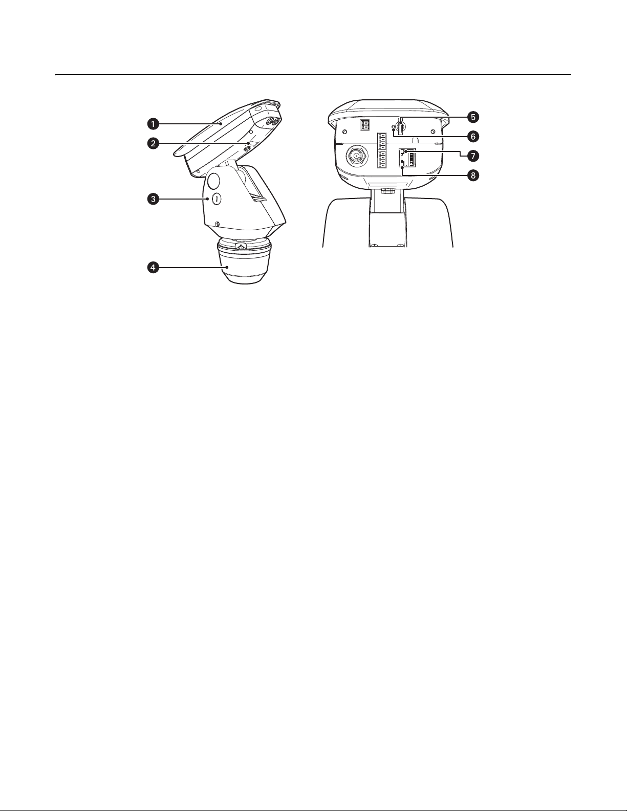
Product Overview
ì
Camera and Enclosure: Powder-coated aluminum IP66 rated enclosure with sun shroud protects the camera in both indoor and outdoor
environments.
î
Product Label: Lists the model number, date code, serial number, and Media Access Control (MAC) address. This information might be
required for setup.
ï
Pan/Tilt: Esprit pan/tilt positioner
Figure 1. Camera Features
ñ
Power Module: Provides power to the unit. If you are using a TXB Series translator board, it will be installed into the power module.
ó
Micro SD Card Slot: Saves a snapshot image to a micro SD card based on alarm activity.
NOTE: The micro SD card must be formatted as FAT32. Other formats are not compatible with the camera.
r
Reset Button: Reboots the camera or restores the camera’s factory default settings. This button is recessed. Using a small tool, such as a
paper clip, press and release the reset button once to reboot the camera. Press and hold the reset button for 10 seconds to restore the
camera to the factory default settings.
s
Ethernet Link LED: Flashes green to indicate that a live network connection is established.
t
Ethernet Activity LED: Glows solid green to indicate that data is being transmitted or received by the camera.
NOTE: Figure 1 shows the camera with the back cover removed. The connectors on the back of the camera are not active. These connections
must be made using the color-coded wire harness attached to the pan/tilt. Refer to Installation on page 7 for more information.
C1332M (5/15) 5
Page 6
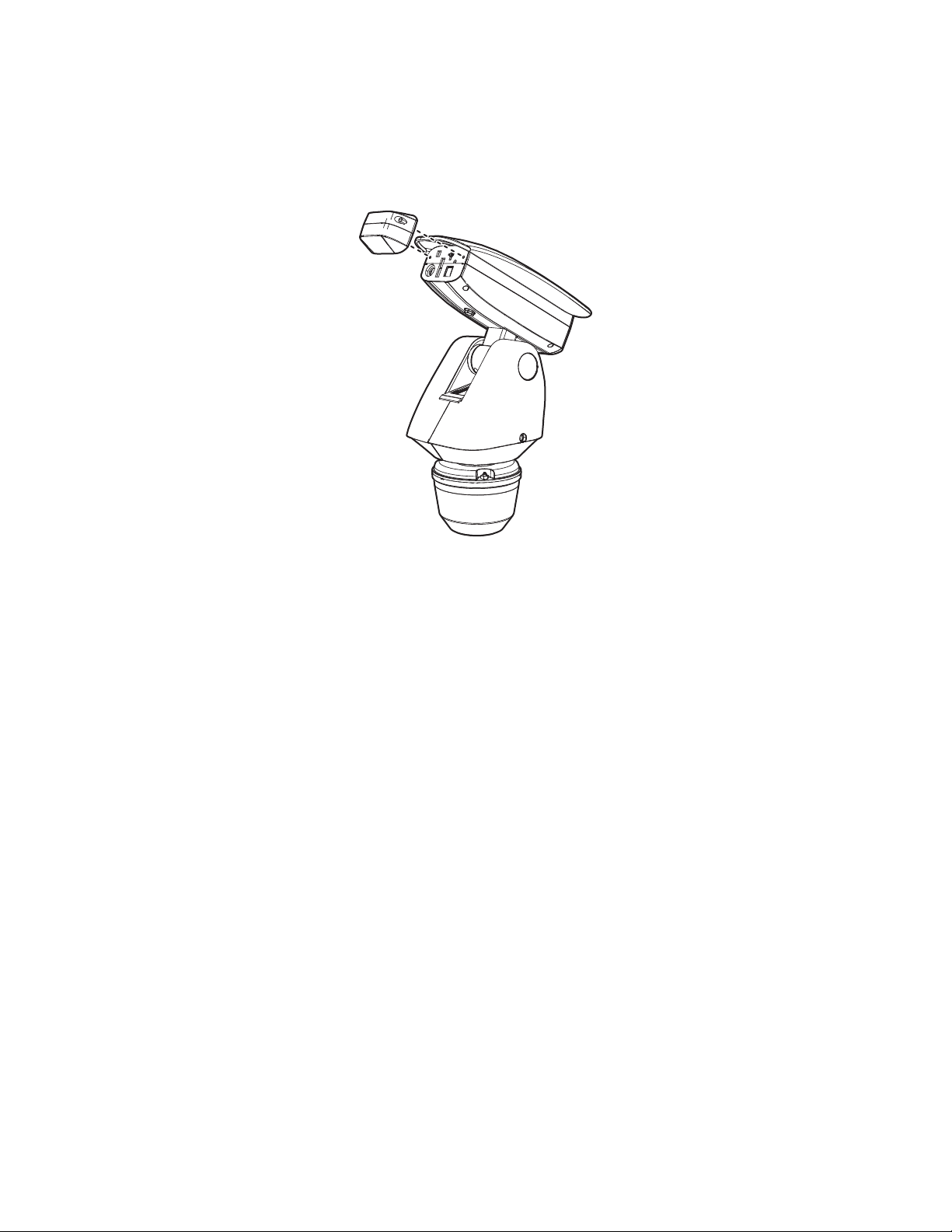
REMOVING THE BACK COVER
To access the micro SD card slot, reset buttons, and Ethernet LEDs, you must first remove the back cover:
1. Loosen the two T20 security screws using a T20 security driver bit (supplied).
2. Remove the back cover.
Figure 2. Removing the Back Cover
6 C1332M (5/15)
Page 7

Installation
1. When installing the device, allow for sufficient clearance between the top of the unit and overhead obstructions. This will prevent
interference when the enclosure is driven to its maximum tilt angles.
NOTE: Do not install the system behind a window or other glass. Glass is opaque to long wave infrared and will block the camera’s view.
2. Remove the power module from the base of the system by loosening the two Phillips screws and lifting the module.
Figure 3. Removing the Power Module
ì
Phillips Screws
î
Power Module
ï
Base
C1332M (5/15) 7
Page 8

3. Attach the base of the system to a recommended mount with the three flathead 10-32 x 1/2-inch screws and washers (supplied).
Figure 4. Attaching the Base
ì
Flathead Mounting Screws
î
Mount
ï
Base
4. If you are installing an optional TXB Series translator board, you must do so before you reinstall the power module to the base. Refer to the
installation manual shipped with the translator board for more information.
5. Route the wires and cables through the center of the mount. Reinstall the power module into the base. The power module can be
positioned in the base in only one orientation.
Figure 5. Routing Wires and Cables
ì
120/230 Voltage Selector Switch
6. 120/230 VAC models only: Set the 120/230 voltage selector switch on the power module to the appropriate voltage.
8 C1332M (5/15)
Page 9

7. Connect all wires and cables.
a. Connect the appropriate power wiring to AC power. Use the two supplied clamp connectors.
Tab le A. Power Wire Colors
120/230 VAC 24 VAC
Black wire Input (AC Line) Black wire AC HI (HOT)
White wire AC Neutral Red wire AC LO (NEUT)
Green wire Ground
b. Connect the video cable.
• Analog installations: Connect the video coaxial cable to the BNC connector.
• IP installations: Connect the video Ethernet cable.
Table B. Ethernet Wire Colors
Orange/white wire TX+
Orange wire TX–
Green/white wire RX+
Green wire RX–
Brown wire N.C.
Brown/white wire N.C.
Blue wire N.C.
Blue/white wire N.C.
c. Connect the wiring for a 2-wire or 4-wire control system. This step does not apply to Coaxitron control systems.
Table C. Control Wire Colors
Green wire RX–
Green/white wire RX+
Brown wire TX–
Brown/white wire TX+
d. Optional: Connect the AUX 2 wiring. Refer to Connecting a Relay Device on page 11 and Connecting Alarms on page 12 for more
detailed information.
Table D. AUX 2 Wire Colors
Violet wire Alarm 1
Yellow wire Alarm 2
Orange wire Alarm 3
Blue wire Alarm COM
Brown wire Relay A1
Green wire Relay A2
Red wire COM
White wire N.O.
Black wire N.C.
e. Optional: Connect the audio wiring. Refer to Connecting Audio on page 14 for more detailed information.
Table E. Audio Wire Colors
Orange/white wire Mic Power +
Orange wire Mic Power –
Blue/white wire Audio In +
Blue wire Audio In –
C1332M (5/15) 9
Page 10

8. Install the mount. Refer to the installation manual supplied with the mount for more information.
9. Turn on the system power. The red power LED is located on the top of the power module (refer to Figure 6 on page 10). If the red LED glows,
turn off the power and proceed to the next step.
NOTE: There might be a delay of approximately 3 minutes between power up and video being displayed in analog installations.
10. Align the triangle mark on the pan/tilt with the triangle mark on the base to ensure that the system connector on the pan/tilt and the base
are also aligned.
Figure 6. Attaching Base and Pan/Tilt
ì
System Connector
î
Power LED
11. Attach the pan/tilt to the base with three 1/4-20 nuts and washers (supplied).
12. Set the receiver address and system baud rate by configuring DIP switches SW1 and SW2.
NOTE: If you have a Coaxitron controller, refer to Appendix on page 15 for switch settings.
To set the DIP switches:
a. Remove the plug from the left cover of the pan/tilt. It is not necessary to remove the pan/tilt cover.
b. Set the baud rate (SW1) and receiver address (SW2). For switch settings, refer to Appendix on page 15.
c. Replace the plug.
10 C1332M (5/15)
Page 11

13. Refer to the Sarix TM Operation manual (part number C1326M) on www.pelco.com for instructions on how to use your Sarix TM system.
NC
NO
COM
USER ACCESSORYSARIX TI
CONNECTING A RELAY DEVICE
NOTE: Relays must be configured using the Web interface.
The Sarix TM has two outputs for activating external devices. It supports both momentary and continuous relay operation.
ON
OFF
ON
OFF
Figure 7. Setting DIP Switches
SW2 SW1
1 2 3 4 5 6 7 8
1 2 3 4 5 6 7 8
DIP SWITCHES
You can operate the relays interactively during an active connection, or they can operate automatically to coincide with certain events. Typical
applications include turning on lights or other electrical devices or activating a door, gate, or lock.
WARNING: Do not exceed the maximum relay ratings of 60 V, 600 mA for Relay A and 60 VDC, 125 VAC for Relay B.
Figure 8. Wiring Diagram for Relay A
C1332M (5/15) 11
Page 12

CONNECTING ALARMS
1 KΩ
A
1
1 KΩ
A
1
NORMALLY OPENNORMALLY CLOSED
NOTE: Alarms must be configured using the Web interface.
The Sarix TM provides three alarm inputs for external signaling devices, such as door contacts or motion detectors. Both normally open and
normally closed devices are supported.
SUPERVISED ALARMS
When an alarm is configured as a supervised alarm, the Sarix TM maintains a constant electrical current through the alarm circuit
(3.3 VDC, 1 kohm). If the alarm circuit length changes, due to an electrical short or a bypass, the voltage fluctuates from its normal state and
activates an alarm.
NOTE: Install the 1-kohm resistor as close to the switch as possible.
USER ACCESSORYSARIX TI
A1
A2
Figure 9. Wiring Diagram for Relay B
Figure 10 illustrates the alarm and no alarm conditions of a supervised alarm input. Whether the alarm is normally closed or normally open,
neither a cut nor a bypass can defeat these alarms.
NORMALLY OPENNORMALLY CLOSED
NO ALARM
GND
ALARM
GND
ALARM
GND
ALARM
GND
1 KΩ
+V
1 KΩ
+V
1 KΩ
+V
CUT
1 KΩ
+V
BYPASS
NO ALARM
GND
ALARM
GND
ALARM
GND
ALARM
GND
1 KΩ
+V
1 KΩ
+V
1 KΩ
+V
CUT
1 KΩ
+V
BYPASS
Figure 10. Supervised Alarm Conditions
Figure 11 illustrates the wiring configuration for supervised alarm inputs.
Figure 11. Supervised Alarm Input Wiring
12 C1332M (5/15)
Page 13

UNSUPERVISED ALARMS
+V
+V
+V
+V
+V
+V
+V
+V
BYPASS
CUT
BYPASS
CUT
GND
ALARM
GND
ALARM
GND
NO ALARM
GND
NO ALARM
GND
NO ALARM
GND
ALARM
GND
NO ALARM
GND
ALARM
NORMALLY OPENNORMALLY CLOSED
A1A1
NORMALLY OPENNORMALLY CLOSED
When an alarm is configured as an unsupervised alarm, an alarm is only activated when the normal alarm state (open or closed) changes.
Figure 12 illustrates the alarm and no alarm conditions of an unsupervised alarm input.
Figure 12. Unsupervised Alarm Conditions
Figure 13 illustrates the wiring configuration for unsupervised alarm inputs.
Figure 13. Normally Closed and Normally Open Unsupervised Alarm Input Wiring
NOTE: A normally closed alarm input can be defeated with a bypass; a normally open input can be defeated with a cut.
ALARM CONNECTIONS
Figure 14 shows how to wire the Sarix TM to an alarm.
ALARM A1
ALARM
Figure 14. Alarm Connections
C1332M (5/15) 13
Page 14

CONNECTING AUDIO
NOTES:
• Improper use of audio/visual recording equipment might subject you to civil and criminal penalties. Applicable laws regarding the use of
such capabilities vary between jurisdictions and might require, among other things, express written consent from the recorded subjects.
You are solely responsible for ensuring strict compliance with such laws and for strict adherence to any/all rights of privacy and personalty.
• The maximum recommended cable length for the audio wiring is 304.8 m (1,000 ft).
• The Sarix TM is designed to work with microphones that have an internal preamplifier and provide professional line-level output (+4 dBu).
• If your microphone is a consumer line-level device (–10 dBu), the audio output may be quieter than you expect. Mic-level devices are not
recommended as they must be amplified to a line-level signal, which often results in excessive noise.
Figure 15. Line-In Audio Wiring
ì
Microphone
î
600-Ohm Impedance Matching Transformer
ï
UTP Wiring
ñ
0 V (zero volt) Return Wire
ó
+12 V Wire
14 C1332M (5/15)
Page 15

Appendix
*SW1-3 and SW1-4 are not used; set them to the OFF position.
Switch Number
†
Turning on the Coaxitron receiver without 75 ohm termination of the analog video output will cause loss of control of the pan/tilt operation and
random movements of the pan/tilt motors.
Table F. Switch Settings for SW1-1 to SW1-4
Baud Rate Settings
Switch Number
2400 4800 9600
SW1-1 OFF ON OFF
SW1-2 OFF OFF ON
SW1-3 OFF* OFF* OFF*
SW1-4 OFF* OFF* OFF*
Table G. Switch Settings for SW1-5 to SW1-8
Settings
OFF ON
SW1-5 For controllers that have more than 32 presets. For American Dynamics controllers (32 presets).
SW1-6 For CM9502 with fixed speed keyboards. For CM9502 with variable speed keyboard.
SW1-7 Coaxitron receiver is off; analog video does not
require a 75 ohm termination.
Coaxitron receiver is on; analog video must be
terminated with a 75 ohm load.
†
SW1-8 1.2 Vp-p video level 1.0 Vp-p video level
C1332M (5/15) 15
Page 16

NOTE: The Esprit will sense and automatically select input from Coaxitron control signals in either the standard or extended mode. Therefore, the DIP
switches settings have no effect on Coaxitron control signals.
Table H. Switch Settings for SW2 (1 of 6)
Receiver Address
P- Ty pe D-Ty p e
Control Control
SW2-1 SW2-2 SW2-3 SW2-4 SW2-5 SW2-6 SW2-7 SW2-8
1 – OFF OFF OFF OFF OFF OFF OFF OFF
2 1 ON OFF OFF OFF OFF OFF OFF OFF
3 2 OFF ON OFF OFF OFF OFF OFF OFF
4 3 ON ON OFF OFF OFF OFF OFF OFF
5 4 OFF OFF ON OFF OFF OFF OFF OFF
6 5 ON OFF ON OFF OFF OFF OFF OFF
7 6 OFF ON ON OFF OFF OFF OFF OFF
8 7 ON ON ON OFF OFF OFF OFF OFF
9 8 OFF OFF OFF ON OFF OFF OFF OFF
10 9 ON OFF OFF ON OFF OFF OFF OFF
11 10 OFF ON OFF ON OFF OFF OFF OFF
12 11 ON ON OFF ON OFF OFF OFF OFF
13 12 OFF OFF ON ON OFF OFF OFF OFF
14 13 ON OFF ON ON OFF OFF OFF OFF
15 14 OFF ON ON ON OFF OFF OFF OFF
16 15 ON ON ON ON OFF OFF OFF OFF
17 16 OFF OFF OFF OFF ON OFF OFF OFF
18 17 ON OFF OFF OFF ON OFF OFF OFF
19 18 OFF ON OFF OFF ON OFF OFF OFF
20 19 ON ON OFF OFF ON OFF OFF OFF
21 20 OFF OFF ON OFF ON OFF OFF OFF
22 21 ON OFF ON OFF ON OFF OFF OFF
23 22 OFF ON ON OFF ON OFF OFF OFF
24 23 ON ON ON OFF ON OFF OFF OFF
25 24 OFF OFF OFF ON ON OFF OFF OFF
26 25 ON OFF OFF ON ON OFF OFF OFF
27 26 OFF ON OFF ON ON OFF OFF OFF
28 27 ON ON OFF ON ON OFF OFF OFF
29 28 OFF OFF ON ON ON OFF OFF OFF
30 29 ON OFF ON ON ON OFF OFF OFF
31 30 OFF ON ON ON ON OFF OFF OFF
32 31 ON ON ON ON ON OFF OFF OFF
– 32 OFF OFF OFF OFF OFF ON OFF OFF
– 33 ON OFF OFF OFF OFF ON OFF OFF
– 34 OFF ON OFF OFF OFF ON OFF OFF
– 35 ON ON OFF OFF OFF ON OFF OFF
– 36OFFOFFONOFFOFFONOFFOFF
– 37 ON OFF ON OFF OFF ON OFF OFF
– 38 OFF ON ON OFF OFF ON OFF OFF
– 39 ONONONOFFOFFONOFFOFF
– 40 OFF OFF OFF ON OFF ON OFF OFF
– 41 ON OFF OFF ON OFF ON OFF OFF
– 42 OFF ON OFF ON OFF ON OFF OFF
– 43 ONONOFFONOFFONOFFOFF
– 44 OFF OFF ON ON OFF ON OFF OFF
– 45 ON OFF ON ON OFF ON OFF OFF
– 46 OFF ON ON ON OFF ON OFF OFF
– 47ONONONONOFFONOFFOFF
– 48 OFF OFF OFF OFF ON ON OFF OFF
– 49 ON OFF OFF OFF ON ON OFF OFF
– 50 OFF ON OFF OFF ON ON OFF OFF
– 51 ONONOFFOFFON ONOFFOFF
– 52 OFF OFF ON OFF ON ON OFF OFF
– 53 ON OFF ON OFF ON ON OFF OFF
– 54 OFF ON ON OFF ON ON OFF OFF
– 55 ON ON ON OFF ON ON OFF OFF
Switch Setting
Table H. Switch Settings for SW2 (2 of 6)
Receiver Address
P-Type D-Type
Control Control
SW2-1 SW2-2 SW2-3 SW2-4 SW2-5 SW2-6 SW2-7 SW2-8
– 56 OFF OFF OFF ON ON ON OFF OFF
– 57ONOFFOFFONONONOFFOFF
– 58 OFF ON OFF ON ON ON OFF OFF
– 59 ON ON OFF ON ON ON OFF OFF
– 60OFFOFFONONONONOFFOFF
– 61 ON OFF ON ON ON ON OFF OFF
– 62 OFF ON ON ON ON ON OFF OFF
– 63ONONONONONONOFFOFF
– 64 OFF OFF OFF OFF OFF OFF ON OFF
– 65 ON OFF OFF OFF OFF OFF ON OFF
– 66 OFF ON OFF OFF OFF OFF ON OFF
– 67 ON ON OFF OFF OFF OFF ON OFF
– 68 OFF OFF ON OFF OFF OFF ON OFF
– 69 ON OFF ON OFF OFF OFF ON OFF
– 70 OFF ON ON OFF OFF OFF ON OFF
– 71 ON ON ON OFF OFF OFF ON OFF
– 72 OFF OFF OFF ON OFF OFF ON OFF
– 73 ONOFFOFFONOFFOFFONOFF
– 74 OFF ON OFF ON OFF OFF ON OFF
– 75 ON ON OFF ON OFF OFF ON OFF
– 76 OFF OFF ON ON OFF OFF ON OFF
– 77 ON OFF ON ON OFF OFF ON OFF
– 78 OFF ON ON ON OFF OFF ON OFF
– 79ONONONONOFFOFFONOFF
– 80 OFF OFF OFF OFF ON OFF ON OFF
– 81 ON OFF OFF OFF ON OFF ON OFF
– 82 OFF ON OFF OFF ON OFF ON OFF
– 83 ON ON OFF OFF ON OFF ON OFF
– 84 OFF OFF ON OFF ON OFF ON OFF
– 85 ONOFFONOFFONOFFONOFF
– 86 OFF ON ON OFF ON OFF ON OFF
– 87 ONONONOFFONOFFONOFF
– 88 OFF OFF OFF ON ON OFF ON OFF
– 89 ONOFFOFFONONOFFONOFF
– 90 OFF ON OFF ON ON OFF ON OFF
– 91 ON ON OFF ON ON OFF ON OFF
– 92 OFF OFF ON ON ON OFF ON OFF
– 93 ON OFF ON ON ON OFF ON OFF
– 94 OFF ON ON ON ON OFF ON OFF
– 95ONONONONONOFFONOFF
– 96 OFF OFF OFF OFF OFF ON ON OFF
– 97 ON OFF OFF OFF OFF ON ON OFF
– 98 OFF ON OFF OFF OFF ON ON OFF
– 99 ON ON OFF OFF OFF ON ON OFF
– 100 OFF OFF ON OFF OFF ON ON OFF
– 101 ON OFF ON OFF OFF ON ON OFF
– 102 OFF ON ON OFF OFF ON ON OFF
– 103 ON ON ON OFF OFF ON ON OFF
– 104 OFF OFF OFF ON OFF ON ON OFF
– 105 ON OFF OFF ON OFF ON ON OFF
– 106 OFF ON OFF ON OFF ON ON OFF
– 107 ON ON OFF ON OFF ON ON OFF
– 108 OFF OFF ON ON OFF ON ON OFF
– 109 ON OFF ON ON OFF ON ON OFF
– 110 OFF ON ON ON OFF ON ON OFF
– 111 ON ON ON ON OFF ON ON OFF
Switch Setting
16 C1332M (5/15)
Page 17

Table H. Switch Settings for SW2 (3 of 6)
Receiver Address
P- Ty pe D-Ty p e
Control Control
SW2-1 SW2-2 SW2-3 SW2-4 SW2-5 SW2-6 SW2-7 SW2-8
– 112 OFF OFF OFF OFF ON ON ON OFF
– 113 ON OFF OFF OFF ON ON ON OFF
– 114 OFF ON OFF OFF ON ON ON OFF
– 115 ON ON OFF OFF ON ON ON OFF
– 116 OFF OFF ON OFF ON ON ON OFF
– 117 ON OFF ON OFF ON ON ON OFF
– 118 OFF ON ON OFF ON ON ON OFF
– 119 ON ON ON OFF ON ON ON OFF
– 120 OFF OFF OFF ON ON ON ON OFF
– 121 ON OFF OFF ON ON ON ON OFF
– 122 OFF ON OFF ON ON ON ON OFF
– 123 ON ON OFF ON ON ON ON OFF
– 124 OFF OFF ON ON ON ON ON OFF
– 125 ON OFF ON ON ON ON ON OFF
–126OFFONONONONONONOFF
– 127 ON ON ON ON ON ON ON OFF
– 128 OFF OFF OFF OFF OFF OFF OFF ON
– 129 ON OFF OFF OFF OFF OFF OFF ON
– 130 OFF ON OFF OFF OFF OFF OFF ON
– 131 ON ON OFF OFF OFF OFF OFF ON
– 132 OFF OFF ON OFF OFF OFF OFF ON
– 133 ON OFF ON OFF OFF OFF OFF ON
– 134 OFF ON ON OFF OFF OFF OFF ON
– 135 ON ON ON OFF OFF OFF OFF ON
– 136 OFF OFF OFF ON OFF OFF OFF ON
– 137 ON OFF OFF ON OFF OFF OFF ON
– 138 OFF ON OFF ON OFF OFF OFF ON
– 139 ON ON OFF ON OFF OFF OFF ON
– 140 OFF OFF ON ON OFF OFF OFF ON
– 141 ON OFF ON ON OFF OFF OFF ON
– 142 OFF ON ON ON OFF OFF OFF ON
– 143 ON ON ON ON OFF OFF OFF ON
– 144 OFF OFF OFF OFF ON OFF OFF ON
– 145 ON OFF OFF OFF ON OFF OFF ON
– 146 OFF ON OFF OFF ON OFF OFF ON
– 147 ON ON OFF OFF ON OFF OFF ON
– 148 OFF OFF ON OFF ON OFF OFF ON
– 149 ON OFF ON OFF ON OFF OFF ON
– 150 OFF ON ON OFF ON OFF OFF ON
– 151 ON ON ON OFF ON OFF OFF ON
– 152 OFF OFF OFF ON ON OFF OFF ON
– 153 ON OFF OFF ON ON OFF OFF ON
– 154 OFF ON OFF ON ON OFF OFF ON
– 155 ON ON OFF ON ON OFF OFF ON
– 156 OFF OFF ON ON ON OFF OFF ON
– 157 ON OFF ON ON ON OFF OFF ON
– 158 OFF ON ON ON ON OFF OFF ON
– 159 ON ON ON ON ON OFF OFF ON
– 160 OFF OFF OFF OFF OFF ON OFF ON
– 161 ON OFF OFF OFF OFF ON OFF ON
– 162 OFF ON OFF OFF OFF ON OFF ON
– 163 ON ON OFF OFF OFF ON OFF ON
– 164 OFF OFF ON OFF OFF ON OFF ON
– 165 ON OFF ON OFF OFF ON OFF ON
– 166 OFF ON ON OFF OFF ON OFF ON
– 167 ON ON ON OFF OFF ON OFF ON
– 168 OFF OFF OFF ON OFF ON OFF ON
– 169 ON OFF OFF ON OFF ON OFF ON
– 170 OFF ON OFF ON OFF ON OFF ON
– 171 ON ON OFF ON OFF ON OFF ON
Switch Setting
Table H. Switch Settings for SW2 (4 of 6)
Receiver Address
P-Type D-Type
Control Control
SW2-1 SW2-2 SW2-3 SW2-4 SW2-5 SW2-6 SW2-7 SW2-8
– 172 OFF OFF ON ON OFF ON OFF ON
– 173 ON OFF ON ON OFF ON OFF ON
– 174 OFF ON ON ON OFF ON OFF ON
– 175 ON ON ON ON OFF ON OFF ON
– 176 OFF OFF OFF OFF ON ON OFF ON
– 177 ON OFF OFF OFF ON ON OFF ON
– 178 OFF ON OFF OFF ON ON OFF ON
– 179 ON ON OFF OFF ON ON OFF ON
– 180 OFF OFF ON OFF ON ON OFF ON
– 181 ON OFF ON OFF ON ON OFF ON
– 182 OFF ON ON OFF ON ON OFF ON
– 183 ON ON ON OFF ON ON OFF ON
– 184 OFF OFF OFF ON ON ON OFF ON
– 185 ON OFF OFF ON ON ON OFF ON
– 186 OFF ON OFF ON ON ON OFF ON
– 187 ON ON OFF ON ON ON OFF ON
– 188 OFF OFF ON ON ON ON OFF ON
– 189 ON OFF ON ON ON ON OFF ON
– 190 OFF ON ON ON ON ON OFF ON
– 191 ON ON ON ON ON ON OFF ON
– 192 OFF OFF OFF OFF OFF OFF ON ON
– 193 ON OFF OFF OFF OFF OFF ON ON
– 194 OFF ON OFF OFF OFF OFF ON ON
– 195 ON ON OFF OFF OFF OFF ON ON
– 196 OFF OFF ON OFF OFF OFF ON ON
– 197 ON OFF ON OFF OFF OFF ON ON
– 198 OFF ON ON OFF OFF OFF ON ON
– 199 ON ON ON OFF OFF OFF ON ON
– 200 OFF OFF OFF ON OFF OFF ON ON
– 201 ON OFF OFF ON OFF OFF ON ON
– 202 OFF ON OFF ON OFF OFF ON ON
– 203 ON ON OFF ON OFF OFF ON ON
– 204 OFF OFF ON ON OFF OFF ON ON
– 205 ON OFF ON ON OFF OFF ON ON
– 206 OFF ON ON ON OFF OFF ON ON
– 207 ON ON ON ON OFF OFF ON ON
– 208 OFF OFF OFF OFF ON OFF ON ON
– 209 ON OFF OFF OFF ON OFF ON ON
– 210 OFF ON OFF OFF ON OFF ON ON
– 211 ON ON OFF OFF ON OFF ON ON
– 212 OFF OFF ON OFF ON OFF ON ON
– 213 ON OFF ON OFF ON OFF ON ON
– 214 OFF ON ON OFF ON OFF ON ON
– 215 ON ON ON OFF ON OFF ON ON
– 216 OFF OFF OFF ON ON OFF ON ON
– 217 ON OFF OFF ON ON OFF ON ON
– 218 OFF ON OFF ON ON OFF ON ON
– 219 ON ON OFF ON ON OFF ON ON
– 220 OFF OFF ON ON ON OFF ON ON
– 221 ON OFF ON ON ON OFF ON ON
– 222 OFF ON ON ON ON OFF ON ON
– 223 ON ON ON ON ON OFF ON ON
– 224 OFF OFF OFF OFF OFF ON ON ON
– 225 ON OFF OFF OFF OFF ON ON ON
– 226 OFF ON OFF OFF OFF ON ON ON
– 227 ON ON OFF OFF OFF ON ON ON
– 228 OFF OFF ON OFF OFF ON ON ON
– 229 ON OFF ON OFF OFF ON ON ON
– 230 OFF ON ON OFF OFF ON ON ON
– 231 ON ON ON OFF OFF ON ON ON
Switch Setting
C1332M (5/15) 17
Page 18

Table H. Switch Settings for SW2 (5 of 6)
Receiver Address
P- Ty pe D-Ty p e
Control Control
SW2-1 SW2-2 SW2-3 SW2-4 SW2-5 SW2-6 SW2-7 SW2-8
– 232 OFF OFF OFF ON OFF ON ON ON
– 233 ON OFF OFF ON OFF ON ON ON
– 234 OFF ON OFF ON OFF ON ON ON
– 235 ON ON OFF ON OFF ON ON ON
– 236 OFF OFF ON ON OFF ON ON ON
– 237 ON OFF ON ON OFF ON ON ON
– 238 OFF ON ON ON OFF ON ON ON
– 239 ON ON ON ON OFF ON ON ON
– 240 OFF OFF OFF OFF ON ON ON ON
– 241 ON OFF OFF OFF ON ON ON ON
– 242 OFF ON OFF OFF ON ON ON ON
– 243 ON ON OFF OFF ON ON ON ON
Switch Setting
Table H. Switch Settings for SW2 (6 of 6)
Receiver Address
P-Type D-Type
Control Control
SW2-1 SW2-2 SW2-3 SW2-4 SW2-5 SW2-6 SW2-7 SW2-8
– 244 OFF OFF ON OFF ON ON ON ON
– 245 ON OFF ON OFF ON ON ON ON
– 246 OFF ON ON OFF ON ON ON ON
– 247 ON ON ON OFF ON ON ON ON
– 248 OFF OFF OFF ON ON ON ON ON
– 249 ON OFF OFF ON ON ON ON ON
– 250 OFF ON OFF ON ON ON ON ON
– 251 ON ON OFF ON ON ON ON ON
– 252 OFF OFF ON ON ON ON ON ON
–253ONOFFONONONONONON
–254OFFONONONONONONON
– 255 ON ON ON ON ON ON ON ON
Switch Setting
18 C1332M (5/15)
Page 19

This equipment contains electrical or electronic components that must be recycled properly to comply with Directive 2002/96/EC of the European Union
regarding the disposal of waste electrical and electronic equipment (WEEE). Contact your local dealer for procedures for recycling this equipment.
REVISION HISTORY
Manual # Date Comments
C1332M 5/15 Original version.
Pelco, the Pelco logo, and other trademarks associa ted with Pelco products referred to in this publication are trademarks of Pelco, Inc. or its affilia tes. © Copyright 2015, Pelco, Inc.
ONVIF and the ONVIF logo are trademarks of ONVIF Inc. All other product names and services are the property of their respective companies. All rights reserved.
Product specifications and availability are subject to change without notice.
Page 20

Pelco by Schneider Electric 3500 Pelco Way Clovis, California 93612-5699 United States
USA & Canada Tel (800) 289-9100 Fax (800) 289-9150
International Tel +1 (559) 292-1981 Fax +1 (559) 348-1120
www.pelco.com www.pelco.com/community
 Loading...