

INSTALLATION
Spectra® IV Series
Spectra® IV SE Series
In-Ceiling Mount Back Box
C3417M-B (11/06)
Installation
1
2
4
5
3
2 C3417M-B (11/06)
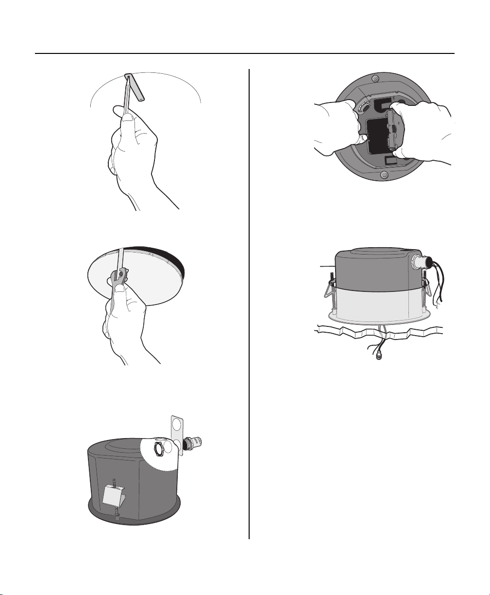
1. Locate the center point of the mounting location and insert the compass tool. Draw a circle.
2. Cut the circle out of the ceiling.
3. Attach the conduit fitting, lock nut, and safety chain bracket. Install a safety chain/cable (not supplied) that will
support up to 16 pounds (7.3 kg).
4. Open the hinged door to the back box. Push the tab lock towards the wall of the unit and lift the door open. Pull
wiring into the back box through the conduit fitting. Refer to Table A, Table B, and Table C for wiring distances.
5. Install the back box by compressing the spring clips and pushing the back box through the hole. Tighten the screws
until you hear a clicking noise.
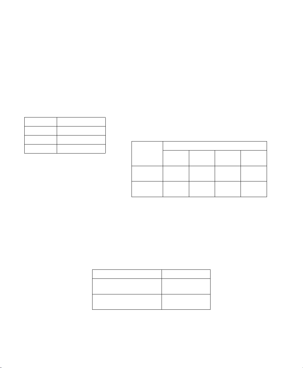
Table A. Video Coaxial Cable
Requirements
Cable Type* Maximum Distance
RG59/U 750 ft (229 m)
RG6/U 1,000 ft (305 m)
RG11/U 1,500 ft (457 m)
*Cable requirements:
75 ohms impedance
All-copper center conductor
All-copper braided shield with 95% braid
coverage
NOTE: Input power for the dome is 24 VAC or 24 VDC. Using 24 VAC input power, power consumption is 23 VA per dome
for indoor models and 73 VA for outdoor models. Using 24 VDC input power, power consumption is 0.7 A (15 watts) for
indoor models and 3 A (65 watts) for outdoor models.
Use a 24 VAC transformer with the following minimum VA:
40 VA per dome For indoor models (without heater)
100 VA per dome For outdoor models (with heater)
.
The following are the recommended maximum distances for 24 VAC
and 24 VDC applications and are calculated with a 10 percent voltage
drop. (Ten percent is generally the maximum allowable voltage drop
for AC- or DC-powered devices.)
AC/DC
Tot a l VA/
Total Watts
23 VA/
15 watts
73 VA/
65 watts
Table C. UTP Wiring Distances
Receiver Maximum Distance
Active
(Video Only)
Passive
(Video, Coaxitron, Pelco V-Sync)
Table B. 24 VAC/24VDC Wiring Distances
Wire Gauge
20 AWG
(0.5 mm
123 ft
(38 m)
39 ft
(12 m)
2
)
18 AWG
(1.0 mm2)
196 ft
(60 m)
62 ft
(19 m)
16 AWG
(1.5 mm2)
311 ft
(95 m)
98 ft
(30 m)
0-3,000 ft
(0-914.4 m)
0-750 ft
(0-228.6 m)
14 AWG
(2.5 mm2)
495 ft
(151 m)
156 ft
(48 m)
NOTE: As a minimum, UTP requires Cat5, 100-ohm twisted pair cable.
C3417M-B (11/06) 3
6
GND
COM
AUX2
GND
1
2
3
4
5
6
7
NO
NC
VIDEO
UTP+ UTP-RX- RX+ TX+TX-PWR- PWR+GND
7
ALARMS
AUX1
4 C3417M-B (11/06)

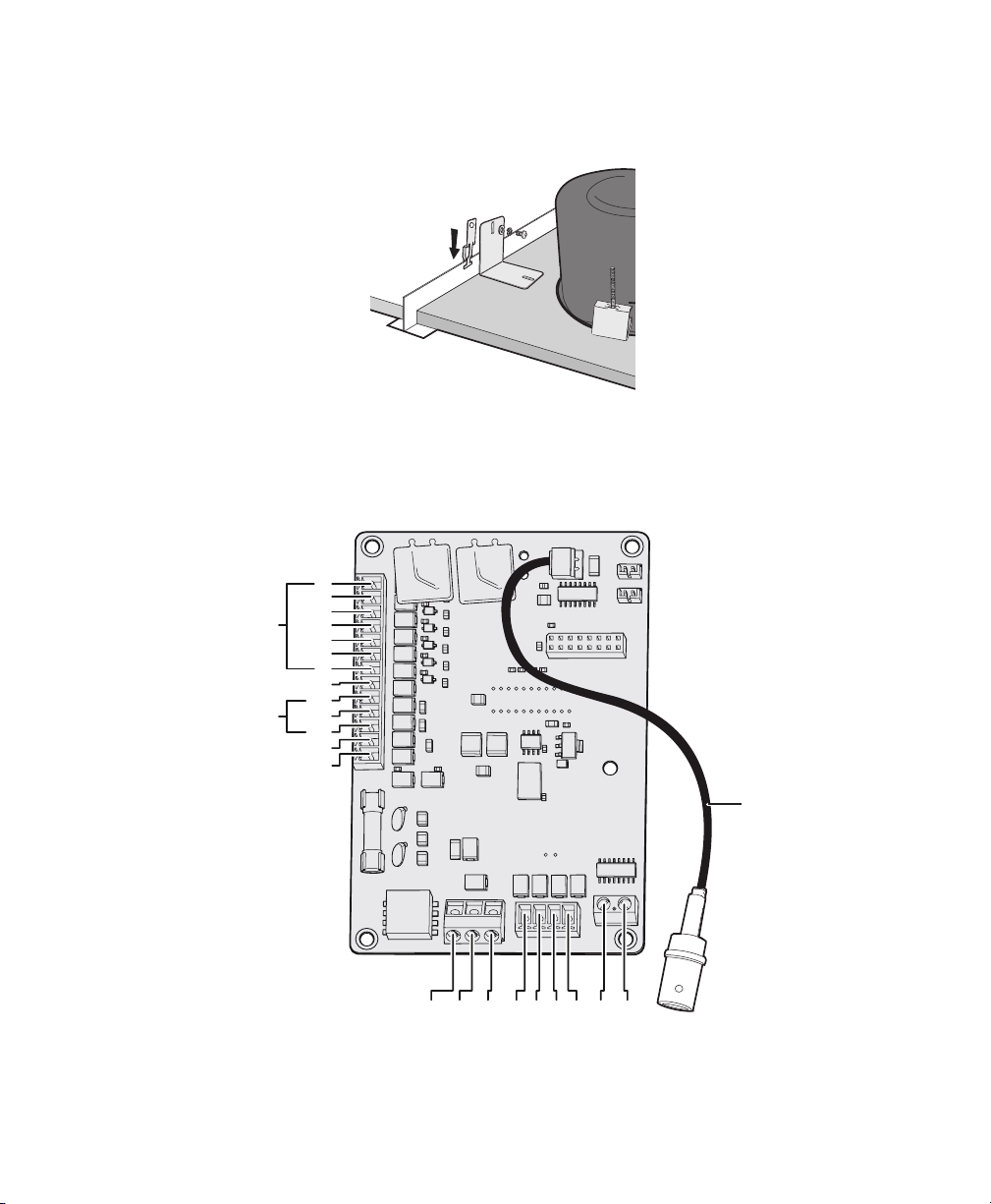
6. Suspended Ceiling Only: Install the ceiling tile with the back box. Attach a T-rail clip on each side of the ceiling
tile.
WARNING: An electrical short in the back box may occur if the metal BNC connector is not completely covered by
the protective boot.
7. Connect wiring to the circuit board inside the back box. When finished, close the door to the back box and turn on the
power. The green LED will light.
NOTES:
• Aux 1: Maximum 2 A at low voltage (<40 V)
Aux 2: Maximum 30 mA at 32 VDC
• If you are using both unshielded twisted pair (UTP) wiring and a translator board, install the UTP wiring before
installing the translator board.
• If you are installing an environmental back box in a railway application, attach a ground wire from the circuit
board power connector to a structural ground using at least 18-gauge wire.
C3417M-B (11/06) 5
 Loading...