

Page 1
INSTALLATION
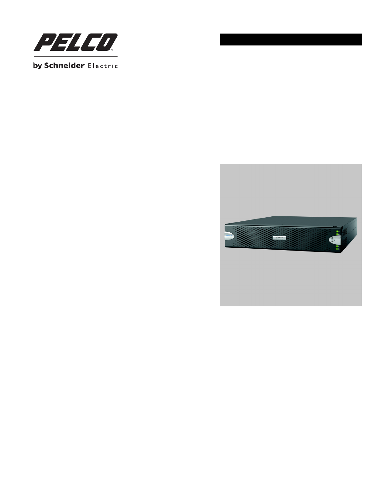
Endura® SM5200
System Manager
C4687M-C (7/13)
Page 2

Page 3

Contents
Important Notices . . . . . . . . . . . . . . . . . . . . . . . . . . . . . . . . . . . . . . . . . . . . . . . . . . . . . . . . . . . . . . . . . . . . . . . . . . . . . . . . . . . . . . . . . . . . . . . . . . . . . 5
Legal Notice . . . . . . . . . . . . . . . . . . . . . . . . . . . . . . . . . . . . . . . . . . . . . . . . . . . . . . . . . . . . . . . . . . . . . . . . . . . . . . . . . . . . . . . . . . . . . . . . . . . . . 5
Regulatory Notices . . . . . . . . . . . . . . . . . . . . . . . . . . . . . . . . . . . . . . . . . . . . . . . . . . . . . . . . . . . . . . . . . . . . . . . . . . . . . . . . . . . . . . . . . . . . . . . . 5
Video Quality Caution . . . . . . . . . . . . . . . . . . . . . . . . . . . . . . . . . . . . . . . . . . . . . . . . . . . . . . . . . . . . . . . . . . . . . . . . . . . . . . . . . . . . . . . . . . . . . . 5
Description. . . . . . . . . . . . . . . . . . . . . . . . . . . . . . . . . . . . . . . . . . . . . . . . . . . . . . . . . . . . . . . . . . . . . . . . . . . . . . . . . . . . . . . . . . . . . . . . . . . . . . . . . . . 6
Models . . . . . . . . . . . . . . . . . . . . . . . . . . . . . . . . . . . . . . . . . . . . . . . . . . . . . . . . . . . . . . . . . . . . . . . . . . . . . . . . . . . . . . . . . . . . . . . . . . . . . . . . .6
Optional Accessories . . . . . . . . . . . . . . . . . . . . . . . . . . . . . . . . . . . . . . . . . . . . . . . . . . . . . . . . . . . . . . . . . . . . . . . . . . . . . . . . . . . . . . . . . . . . . . 6
Before You Begin . . . . . . . . . . . . . . . . . . . . . . . . . . . . . . . . . . . . . . . . . . . . . . . . . . . . . . . . . . . . . . . . . . . . . . . . . . . . . . . . . . . . . . . . . . . . . . . . . . . . . . 7
Package Contents . . . . . . . . . . . . . . . . . . . . . . . . . . . . . . . . . . . . . . . . . . . . . . . . . . . . . . . . . . . . . . . . . . . . . . . . . . . . . . . . . . . . . . . . . . . . . . . . . 7
Product Labels. . . . . . . . . . . . . . . . . . . . . . . . . . . . . . . . . . . . . . . . . . . . . . . . . . . . . . . . . . . . . . . . . . . . . . . . . . . . . . . . . . . . . . . . . . . . . . . . . . .10
User Supplied Parts List . . . . . . . . . . . . . . . . . . . . . . . . . . . . . . . . . . . . . . . . . . . . . . . . . . . . . . . . . . . . . . . . . . . . . . . . . . . . . . . . . . . . . . . . . . .10
Product Overview. . . . . . . . . . . . . . . . . . . . . . . . . . . . . . . . . . . . . . . . . . . . . . . . . . . . . . . . . . . . . . . . . . . . . . . . . . . . . . . . . . . . . . . . . . . . . . . . . . . . . 11
Rear Panel. . . . . . . . . . . . . . . . . . . . . . . . . . . . . . . . . . . . . . . . . . . . . . . . . . . . . . . . . . . . . . . . . . . . . . . . . . . . . . . . . . . . . . . . . . . . . . . . . . . . . . 11
Front Panel Controls and Indicators . . . . . . . . . . . . . . . . . . . . . . . . . . . . . . . . . . . . . . . . . . . . . . . . . . . . . . . . . . . . . . . . . . . . . . . . . . . . . . . . . . 12
Installation . . . . . . . . . . . . . . . . . . . . . . . . . . . . . . . . . . . . . . . . . . . . . . . . . . . . . . . . . . . . . . . . . . . . . . . . . . . . . . . . . . . . . . . . . . . . . . . . . . . . . . . . . . 14
Installing the Unit on a Desktop . . . . . . . . . . . . . . . . . . . . . . . . . . . . . . . . . . . . . . . . . . . . . . . . . . . . . . . . . . . . . . . . . . . . . . . . . . . . . . . . . . . . . 14
Rack-Mounting Requirements . . . . . . . . . . . . . . . . . . . . . . . . . . . . . . . . . . . . . . . . . . . . . . . . . . . . . . . . . . . . . . . . . . . . . . . . . . . . . . . . . . . . . . 14
Rack-Mounting the Unit . . . . . . . . . . . . . . . . . . . . . . . . . . . . . . . . . . . . . . . . . . . . . . . . . . . . . . . . . . . . . . . . . . . . . . . . . . . . . . . . . . . . . . . . . . .15
Installing the Drive Array . . . . . . . . . . . . . . . . . . . . . . . . . . . . . . . . . . . . . . . . . . . . . . . . . . . . . . . . . . . . . . . . . . . . . . . . . . . . . . . . . . . . . . . . . . 19
Connecting the Power Supply. . . . . . . . . . . . . . . . . . . . . . . . . . . . . . . . . . . . . . . . . . . . . . . . . . . . . . . . . . . . . . . . . . . . . . . . . . . . . . . . . . . . . . . 20
Connecting to the Network. . . . . . . . . . . . . . . . . . . . . . . . . . . . . . . . . . . . . . . . . . . . . . . . . . . . . . . . . . . . . . . . . . . . . . . . . . . . . . . . . . . . . . . . . 21
Product Serial Number Label Placement. . . . . . . . . . . . . . . . . . . . . . . . . . . . . . . . . . . . . . . . . . . . . . . . . . . . . . . . . . . . . . . . . . . . . . . . . . 10
Installing the Drive Carriers. . . . . . . . . . . . . . . . . . . . . . . . . . . . . . . . . . . . . . . . . . . . . . . . . . . . . . . . . . . . . . . . . . . . . . . . . . . . . . . . . . . .19
Startup and Shutdown. . . . . . . . . . . . . . . . . . . . . . . . . . . . . . . . . . . . . . . . . . . . . . . . . . . . . . . . . . . . . . . . . . . . . . . . . . . . . . . . . . . . . . . . . . . . . . . . . 22
Starting Up the Unit . . . . . . . . . . . . . . . . . . . . . . . . . . . . . . . . . . . . . . . . . . . . . . . . . . . . . . . . . . . . . . . . . . . . . . . . . . . . . . . . . . . . . . . . . . . . . . 22
Shutting Down the Unit . . . . . . . . . . . . . . . . . . . . . . . . . . . . . . . . . . . . . . . . . . . . . . . . . . . . . . . . . . . . . . . . . . . . . . . . . . . . . . . . . . . . . . . . . . . 22
Performing a Remote Shutdown . . . . . . . . . . . . . . . . . . . . . . . . . . . . . . . . . . . . . . . . . . . . . . . . . . . . . . . . . . . . . . . . . . . . . . . . . . . . . . . . 22
Performing a Local Shutdown . . . . . . . . . . . . . . . . . . . . . . . . . . . . . . . . . . . . . . . . . . . . . . . . . . . . . . . . . . . . . . . . . . . . . . . . . . . . . . . . . . 22
Restarting the Unit . . . . . . . . . . . . . . . . . . . . . . . . . . . . . . . . . . . . . . . . . . . . . . . . . . . . . . . . . . . . . . . . . . . . . . . . . . . . . . . . . . . . . . . . . . . . . . .23
Troubleshooting . . . . . . . . . . . . . . . . . . . . . . . . . . . . . . . . . . . . . . . . . . . . . . . . . . . . . . . . . . . . . . . . . . . . . . . . . . . . . . . . . . . . . . . . . . . . . . . . . . . . . . 24
Specifications . . . . . . . . . . . . . . . . . . . . . . . . . . . . . . . . . . . . . . . . . . . . . . . . . . . . . . . . . . . . . . . . . . . . . . . . . . . . . . . . . . . . . . . . . . . . . . . . . . . . . . . 25
Appendixes . . . . . . . . . . . . . . . . . . . . . . . . . . . . . . . . . . . . . . . . . . . . . . . . . . . . . . . . . . . . . . . . . . . . . . . . . . . . . . . . . . . . . . . . . . . . . . . . . . . . . . . . . 28
Appendix A: Installing an Uninterruptible Power Supply. . . . . . . . . . . . . . . . . . . . . . . . . . . . . . . . . . . . . . . . . . . . . . . . . . . . . . . . . . . . . . . . . . 28
Appendix B: Migrating Data from an SM5000. . . . . . . . . . . . . . . . . . . . . . . . . . . . . . . . . . . . . . . . . . . . . . . . . . . . . . . . . . . . . . . . . . . . . . . . . . 29
C4687M-C (7/13) 3
Page 4

List of Illustrations
1 Major Package Components. . . . . . . . . . . . . . . . . . . . . . . . . . . . . . . . . . . . . . . . . . . . . . . . . . . . . . . . . . . . . . . . . . . . . . . . . . . . . . . . . . . . . . . . . 7
2 Accessory Pack . . . . . . . . . . . . . . . . . . . . . . . . . . . . . . . . . . . . . . . . . . . . . . . . . . . . . . . . . . . . . . . . . . . . . . . . . . . . . . . . . . . . . . . . . . . . . . . . . . . 8
3 Rack Mount Kit . . . . . . . . . . . . . . . . . . . . . . . . . . . . . . . . . . . . . . . . . . . . . . . . . . . . . . . . . . . . . . . . . . . . . . . . . . . . . . . . . . . . . . . . . . . . . . . . . . . 9
4 Rear Panel Layout . . . . . . . . . . . . . . . . . . . . . . . . . . . . . . . . . . . . . . . . . . . . . . . . . . . . . . . . . . . . . . . . . . . . . . . . . . . . . . . . . . . . . . . . . . . . . . . . 11
5 SM5200 Front Panel Layout (Bezel Open) . . . . . . . . . . . . . . . . . . . . . . . . . . . . . . . . . . . . . . . . . . . . . . . . . . . . . . . . . . . . . . . . . . . . . . . . . . . . . 12
6 Front Bezel Indicators (Bezel Closed) . . . . . . . . . . . . . . . . . . . . . . . . . . . . . . . . . . . . . . . . . . . . . . . . . . . . . . . . . . . . . . . . . . . . . . . . . . . . . . . . . 12
7 Removing the Chassis Brackets from the Sliding Brackets . . . . . . . . . . . . . . . . . . . . . . . . . . . . . . . . . . . . . . . . . . . . . . . . . . . . . . . . . . . . . . . . 15
8 Attaching the Chassis Brackets . . . . . . . . . . . . . . . . . . . . . . . . . . . . . . . . . . . . . . . . . . . . . . . . . . . . . . . . . . . . . . . . . . . . . . . . . . . . . . . . . . . . .16
9 Attaching the L-Shaped Brackets to the Sliding Brackets. . . . . . . . . . . . . . . . . . . . . . . . . . . . . . . . . . . . . . . . . . . . . . . . . . . . . . . . . . . . . . . . . 16
10 Support Rail Assembly . . . . . . . . . . . . . . . . . . . . . . . . . . . . . . . . . . . . . . . . . . . . . . . . . . . . . . . . . . . . . . . . . . . . . . . . . . . . . . . . . . . . . . . . . . . . 17
11 Attaching the Brackets to the Rack . . . . . . . . . . . . . . . . . . . . . . . . . . . . . . . . . . . . . . . . . . . . . . . . . . . . . . . . . . . . . . . . . . . . . . . . . . . . . . . . . .17
12 Installing the Unit in the Rack . . . . . . . . . . . . . . . . . . . . . . . . . . . . . . . . . . . . . . . . . . . . . . . . . . . . . . . . . . . . . . . . . . . . . . . . . . . . . . . . . . . . . . 18
13 Aligning the Chassis Bracket and the Sliding Bracket. . . . . . . . . . . . . . . . . . . . . . . . . . . . . . . . . . . . . . . . . . . . . . . . . . . . . . . . . . . . . . . . . . . . 18
14 Numbered Hard Drive Bays for SM5200 . . . . . . . . . . . . . . . . . . . . . . . . . . . . . . . . . . . . . . . . . . . . . . . . . . . . . . . . . . . . . . . . . . . . . . . . . . . . . . 19
15 Opening the Bezel. . . . . . . . . . . . . . . . . . . . . . . . . . . . . . . . . . . . . . . . . . . . . . . . . . . . . . . . . . . . . . . . . . . . . . . . . . . . . . . . . . . . . . . . . . . . . . . . 20
16 Installing a Drive Carrier. . . . . . . . . . . . . . . . . . . . . . . . . . . . . . . . . . . . . . . . . . . . . . . . . . . . . . . . . . . . . . . . . . . . . . . . . . . . . . . . . . . . . . . . . . . 20
17 Closing and Locking a Drive Carrier . . . . . . . . . . . . . . . . . . . . . . . . . . . . . . . . . . . . . . . . . . . . . . . . . . . . . . . . . . . . . . . . . . . . . . . . . . . . . . . . . . 20
18 Network Cable Connection. . . . . . . . . . . . . . . . . . . . . . . . . . . . . . . . . . . . . . . . . . . . . . . . . . . . . . . . . . . . . . . . . . . . . . . . . . . . . . . . . . . . . . . . .21
19 Starting Up the Unit . . . . . . . . . . . . . . . . . . . . . . . . . . . . . . . . . . . . . . . . . . . . . . . . . . . . . . . . . . . . . . . . . . . . . . . . . . . . . . . . . . . . . . . . . . . . . . 22
20 Connecting a UPS . . . . . . . . . . . . . . . . . . . . . . . . . . . . . . . . . . . . . . . . . . . . . . . . . . . . . . . . . . . . . . . . . . . . . . . . . . . . . . . . . . . . . . . . . . . . . . . . 28
4 C4687M-C (7/13)
Page 5

Important Notices
LEGAL NOTICE
SOME PELCO EQUIPMENT CONTAINS, AND THE SOFTWARE ENABLES, AUDIO/VISUAL AND RECORDING CAPABILITIES, THE IMPROPER USE OF
WHICH MAY SUBJECT YOU TO CIVIL AND CRIMINAL PENALTIES. APPLICABLE LAWS REGARDING THE USE OF SUCH CAPABILITIES VARY
BETWEEN JURISDICTIONS AND MAY REQUIRE, AMONG OTHER THINGS, EXPRESS WRITTEN CONSENT FROM RECORDED SUBJECTS. YOU
ARE SOLELY RESPONSIBLE FOR INSURING STRICT COMPLIANCE WITH SUCH LAWS AND FOR STRICT ADHERENCE TO ANY/ALL RIGHTS OF
PRIVACY AND PERSONALTY. USE OF THIS EQUIPMENT AND/OR SOFTWARE FOR ILLEGAL SURVEILLANCE OR MONITORING SHALL BE DEEMED
UNAUTHORIZED USE IN VIOLATION OF THE END USER SOFTWARE AGREEMENT AND RESULT IN THE IMMEDIATE TERMINATION OF YOUR
LICENSE RIGHTS THEREUNDER.
REGULATORY NOTICES
This device complies with Part 15 of the FCC Rules. Operation is subject to the following two conditions: (1) this device may not cause harmful
interference, and (2) this device must accept any interference received, including interference that may cause undesired operation.
RADIO AND TELEVISION INTERFERENCE
This equipment has been tested and found to comply with the limits of a Class A digital device, pursuant to Part 15 of the FCC rules. These limits
are designed to provide reasonable protection against harmful interference when the equipment is operated in a commercial environment.
This equipment generates, uses, and can radiate radio frequency energy and, if not installed and used in accordance with the instruction manual,
may cause harmful interference to radio communications. Operation of this equipment in a residential area is likely to cause harmful interference
in which case the user will be required to correct the interference at his own expense.
Changes and Modifications not expressly approved by the manufacturer or registrant of this equipment can void your authority to operate this
equipment under Federal Communications Commission’s rules.
In order to maintain compliance with FCC regulations shielded cables must be used with this equipment. Operation with non-approved
equipment or unshielded cables is likely to result in interference to radio and television reception.
This Class A digital apparatus complies with Canadian ICES-003.
Cet appareil numérique de la classe A est conforme à la norme NMB-003 du Canada.
VIDEO QUALITY CAUTION
FRAME RATE NOTICE REGARDING USER-SELECTED OPTIONS
Pelco, Inc. systems are capable of providing high quality video for both live viewing and playback. However, the systems can be used in lower
quality modes, which can degrade picture quality, to allow for a slower rate of data transfer and to reduce the amount of video data stored. The
picture quality can be degraded by either lowering the resolution, reducing the picture rate, or both. A picture degraded by having a reduced
resolution may result in an image that is less clear or even indiscernible. A picture degraded by reducing the picture rate has fewer frames per
second, which can result in images that appear to jump or move more quickly than normal during playback. Lower frame rates may result in a key
event not being recorded by the system.
Judgment as to the suitability of the products for users’ purposes is solely the users’ responsibility. Users should refer to the operation manuals
for cautionary statements regarding user selected options and how they might affect video quality. Users shall determine the suitability of the
products for their own intended application, picture rate and picture quality. The video analytic behaviors provide a large spectrum of settings
that allow the behaviors to be used in a variety of applications. Selection of appropriate settings for proper detection in user applications is the
sole responsibility of users. This equipment is intended to assist users in identifying situations of interest to users. Users have the sole
responsibility of determining the appropriate response. In the event users intend to use the video for evidentiary purposes in a judicial proceeding
or otherwise, users should consult with their attorney regarding any particular requirements for such use.
C4687M-C (7/13) 5
Page 6

Description
The SM5200 system manager is a network appliance that serves as the system management component of the Endura® IP video management
solution.
This document provides instructions for mounting and installing your SM5200 hardware. Once you have installed the SM5200, you will have to
perform some software configuration; for more information, refer to your SM5200 System Manager Configuration manual.
MODELS
Model numbers for the SM5200 consist of the base model, the amount of video storage, and the power cord country code. For example, a unit
with 12 TB of video storage with a power cord for use in the United Kingdom is SM5200-120-UK.
NOTE: Models shipped to China do not include power cords. A CCC approved power cord must be used to power this equipment when used
in China.
Table A. SM5200 Model Numbers
Model Video Storage* Country Code
SM5200-03 3 TB US = North America
SM5200-12 12 TB
*Storage capacities are subject to change. Contact Pelco
Product Support for current capacity information.
EU = Europe
UK = United Kingdom
CN = China
AU = Australia
AR = Argentina
OPTIONAL ACCESSORIES
SM5200-SSD-40GB Replacement SSD for drive bays 1 or 2
SM5200-HDD-3TB Video Storage HDD for drive bays 3 to 6
6 C4687M-C (7/13)
Page 7
Before You Begin
PACKAGE CONTENTS
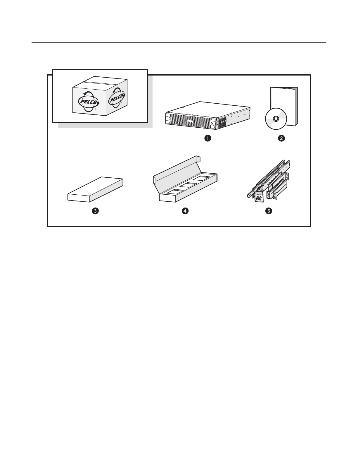
Figure 1. Major Package Components
ì
SM5200 System Manager
î
SM5200-LIT Literature Kit: Includes product manual, product
badge, and resource disc
ï
Accessory Pack
ñ
Hard Drive Pack (hard drives in carriers)
NOTE: Number of hard drives depends on model.
ó
Rack Mount Kit (1 ea.)
C4687M-C (7/13) 7
Page 8
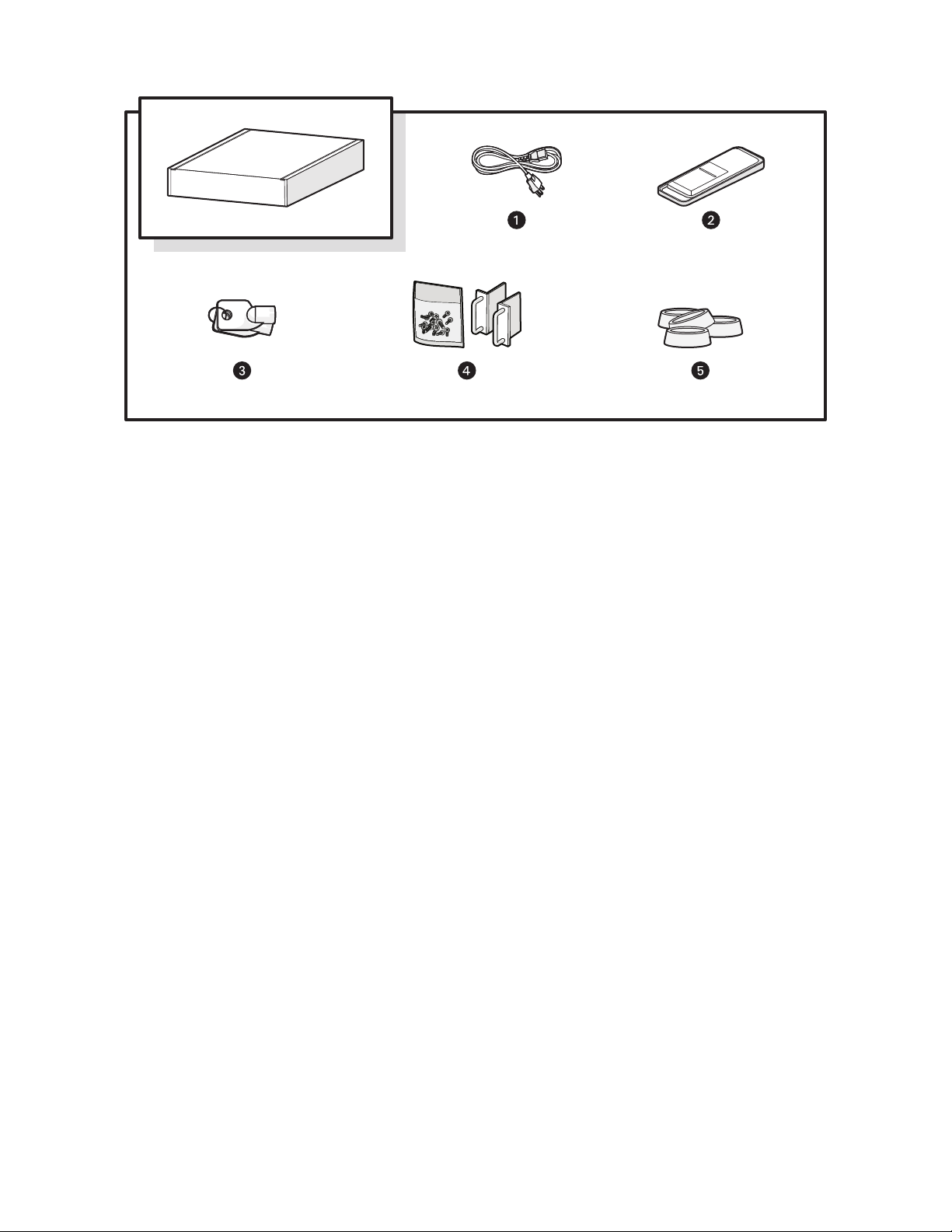
Figure 2. Accessory Pack
ì
Power Cord (based on country designation (1 ea.)
NOTE: Units shipped to China do not include power cords; a CCC
approved power cord must be used to power this equipment
when used in China.
î
USB Flash Drive (4GB) for System Migration (1 ea.)
ï
Bezel Keys (2 ea.)
ñ
Chassis Handles (2 ea.); Includes Phillips Screws for Installation.
ó
Rubber Feet (4 ea.)
8 C4687M-C (7/13)
Page 9
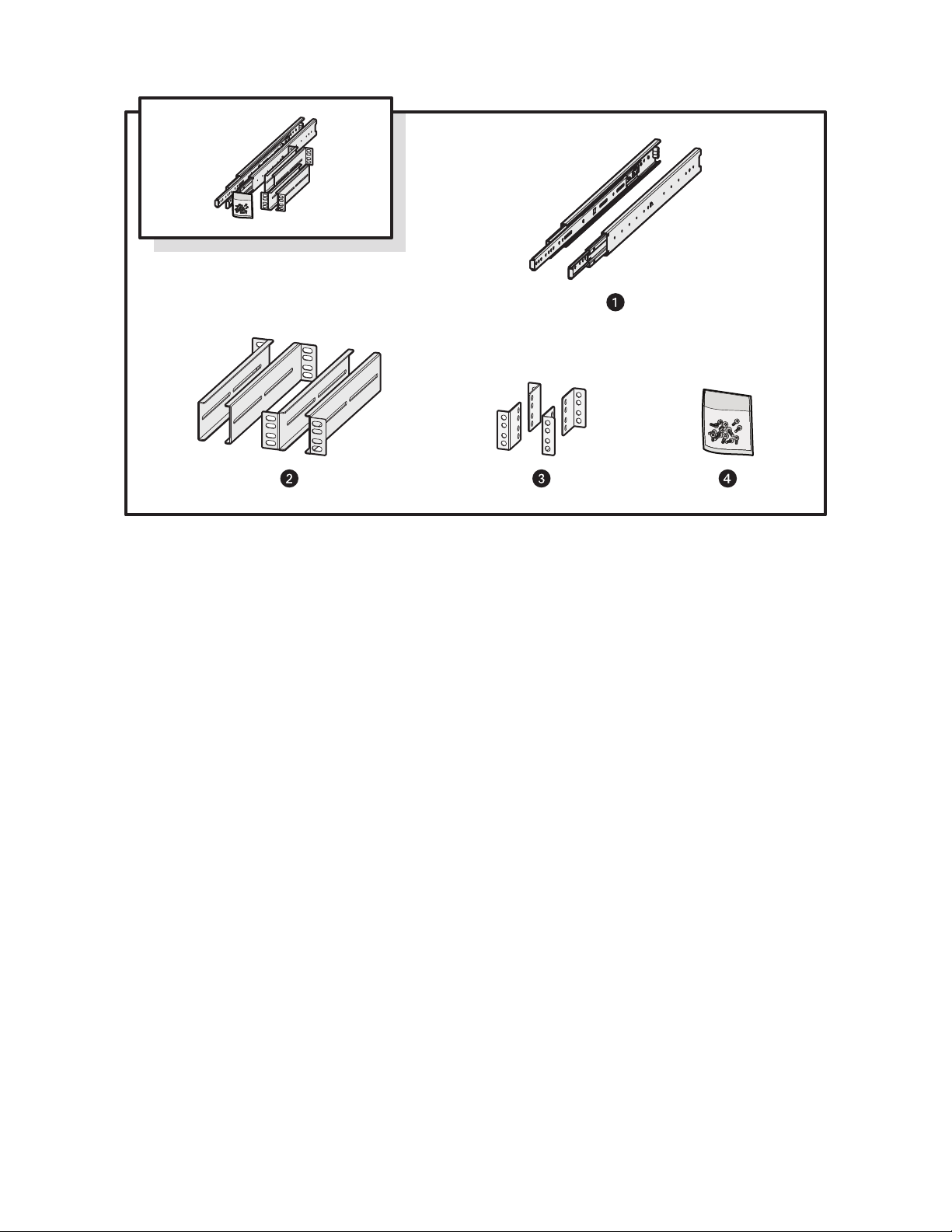
Figure 3. Rack Mount Kit
ì
Chassis Brackets (2 ea.),
Sliding Brackets (2 ea.)
î
L-Shaped Brackets (4 ea.)
ï
L-Shaped Plate Nuts (4 ea.)
ñ
M5 x 8L-H2.5 Round Head Nickel Screws (18 ea.),
M4 x 6L-H2.5 Round Head Nickel Screws (18 ea.),
4.2 x 11 x 0.8 Nickel Washers (optional, 10 ea.)
C4687M-C (7/13) 9
Page 10

PRODUCT LABELS
PRODUCT SERIAL NUMBER LABEL PLACEMENT
Product serial number labels help identify your system and its factory configuration if your unit or its components should require service.
Three labels citing your product’s serial number are attached to the unit. One label is attached to the upper-right corner of the rear of the unit.
A second, smaller label is attached to the inside left of the bezel.
Because rack mounting and other installation options may obscure the factory-applied labels, a third set of labels is provided for you to attach to
your product documentation or to another product location that will not be obscured by installation.
To use these labels:
1. Locate the label attached to the outside of the front bezel with a yellow sticker that reads, “Extra serial number label: remove prior to
installation.”
2. Remove the yellow sticker.
3. Peel off the back of the label and attach it to this manual, other product documentation, or an unobstructed product location.
USER SUPPLIED PARTS LIST
The following installation tools and parts are needed for installation, but not supplied.
• Power source (110/220 VAC)
• Small Phillips screwdriver, if mounting the unit into a rack
10 C4687M-C (7/13)
Page 11

Product Overview
REAR PANEL
Figure 4. Rear Panel Layout
ì
Rear Chassis Fan
î
Power Receptacle
ï
Reserved (do not use)
ñ
Ethernet Ports
• Network Port 1 (left is primary)
• Network Port 2 (right is secondary)
ó
Card Slots
r
Reserved (do not use)
s
Audio Out
t
Reserved (do not use)
u
USB 3.0 Ports
~í
USB 2.0 Ports
C4687M-C (7/13) 11
Page 12

FRONT PANEL CONTROLS AND INDICATORS
Endura
SM5200 Series
Figure 5. SM5200 Front Panel Layout (Bezel Open)
Figure 6. Front Bezel Indicators (Bezel Closed)
ì
Unit Status
• Green: The unit is functioning normally.
• Flashing green: The unit is starting or shutting down.
• Amber: The unit is nearing operational thresholds; maintenance is recommended.
• Red: The unit is in an error condition (refer to Troubleshooting on page 24).
î
Network Port 1 Speed and Activity
• Off: The unit is not connected to the network.
• Solid green: The unit is connected at 1000 Mbps.
• Solid amber: The unit is connected at 100 Mbps.
• Solid red: The unit is connected at 10 Mbps.
NOTE: For proper operation, you must have a gigabit (1000 Mbps) connection.
ï
Network Port 2 Speed and Activity
• Off: The unit is not connected to the network.
• Solid green: The unit is connected at 1000 Mbps.
• Solid amber: The unit is connected at 100 Mbps.
• Solid red: The unit is connected at 10 Mbps.
NOTE: For proper operation, you must have a gigabit (1000 Mbps) connection.
ñ
Software Status
• Green: The software is operating normally.
• Amber: A minor software malfunction is detected (for example, excessive packet loss).
• Red: A fatal software error has occurred (for example, ceasing to record).
ó
Power Button
• Push the power button to turn the unit on.
• Push and hold the power button to turn the unit off.
12 C4687M-C (7/13)
Page 13

r
Drive Status
The drive status indicators report the operating status of each individual drive.
• Flashing green: Read or write activity is occurring on the hard drive.
• Solid red: A problem exists with the hard drive.
• Flashing green/red: The hard drive is initializing.
s
USB Ports
The SM5200 includes one USB 2.0 port on the front panel and four ports on the rear panel
(two USB 3.0 ports and two USB 2.0 ports). These ports can be used to connect a UPS unit,
or they can be used to conduct diagnostic and troubleshooting activities.
C4687M-C (7/13) 13
Page 14

Installation
INSTALLING THE UNIT ON A DESKTOP
WARNING: Do not place the unit on its side
To install the unit on a desktop:
1. Secure rubber feet (included) to the unit’s bottom panel.
2. Position the unit to allow for cable and power cord clearance.
RACK-MOUNTING REQUIREMENTS
The unit occupies 2 rack units (RU) of vertical rack space (8.9 cm or 3.5 inches) in an industry standard 48 cm (19-inch) equipment rack. The
hardware required for rack-mounting is included with the unit.
The rack must meet the following requirements:
• Rack standard: 48 cm (19 inches), EIA-310-D compliant (rear column required)
• Rack column depth: 50.8 to 76.2 cm (20 to 30 inches)
• Column mounting hole provisions: 10-32 UNF-2B threaded holes or square window holes on front and rear columns
• Door systems (optional): Front doors must have at least 5.1 cm (2 inches) between the unit bezel and the inside of the door; rear doors
may be used only on rack columns that are more than 66 cm (26 inches) deep
WARNINGS:
• Make sure the unit is level in the rack.
• Do not attach the unit’s rubber feet when rack-mounting the unit.
• Provide proper ventilation when mounting the unit in a rack. Slots and openings in the cabinet provide ventilation to prevent the unit
from overheating. Do not block these openings. Never place the unit near or over a radiator or heat register.
NOTE: Refer to Figure 3 on page 9 for the description of the hardware used in this installation.
14 C4687M-C (7/13)
Page 15
RACK-MOUNTING THE UNIT
1. Install the chassis handles (supplied):
a. Align the screw holes on the chassis handles with holes near the front of the chassis.
b. Insert and tighten the four Phillips flat head screws (supplied).
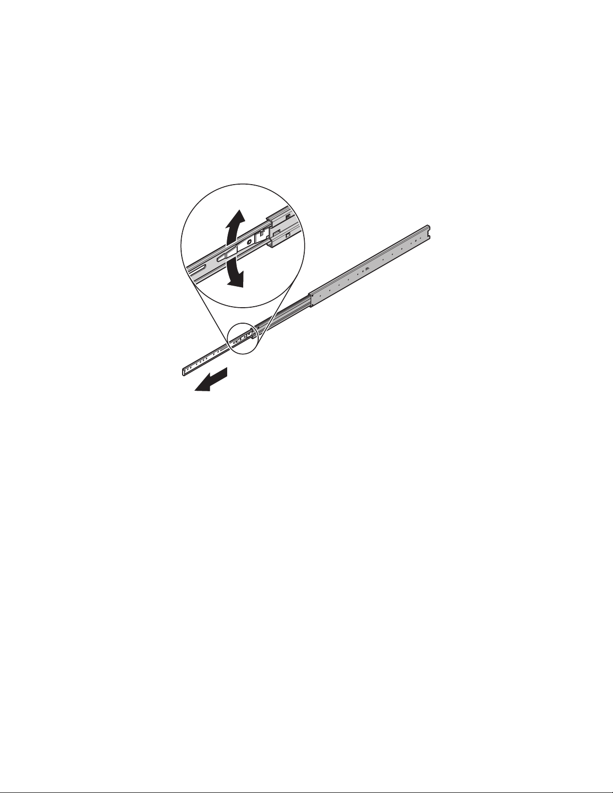
2. Remove the chassis brackets from the sliding brackets (both supplied):
a. Slide both chassis brackets away from the sliding brackets until they lock in place.
b. Release the chassis brackets from the sliding brackets. Press down on the release for the right set of rails and press up for the left set
of rails.
Figure 7. Removing the Chassis Brackets from the Sliding Brackets
C4687M-C (7/13) 15
Page 16
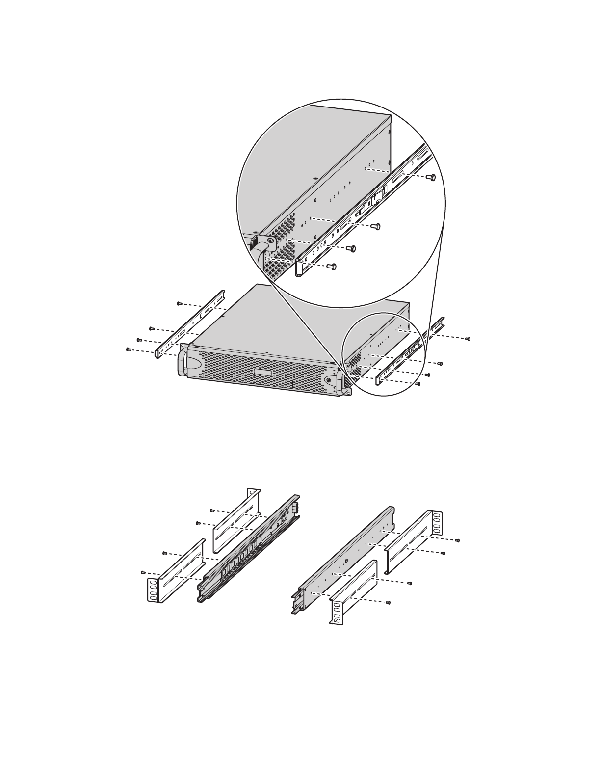
3. Attach the chassis brackets to the sides of the unit (refer to Figure 8) using four M4 x 6L-H2.5 round head nickel screws (supplied) for each
bracket. Align the chassis brackets starting with the threaded hole closest to the unit’s front panel, with the slotted ends facing the rear of
the unit.
Figure 8. Attaching the Chassis Brackets
4. Attach L-shaped brackets (supplied) to the front and rear of both sliding brackets using two M4 x 6L-H2.5 round head nickel screws per
L-shaped bracket. Leave all eight screws untightened until later in the installation.
NOTE: You can insert the optional 4.2 x 11 x 0.8 nickel washers (supplied) between the screws and the L-shaped brackets to allow the brackets
to slide easier when attaching them to the rack in later steps.
Figure 9. Attaching the L-Shaped Brackets to the Sliding Brackets
16 C4687M-C (7/13)
Page 17
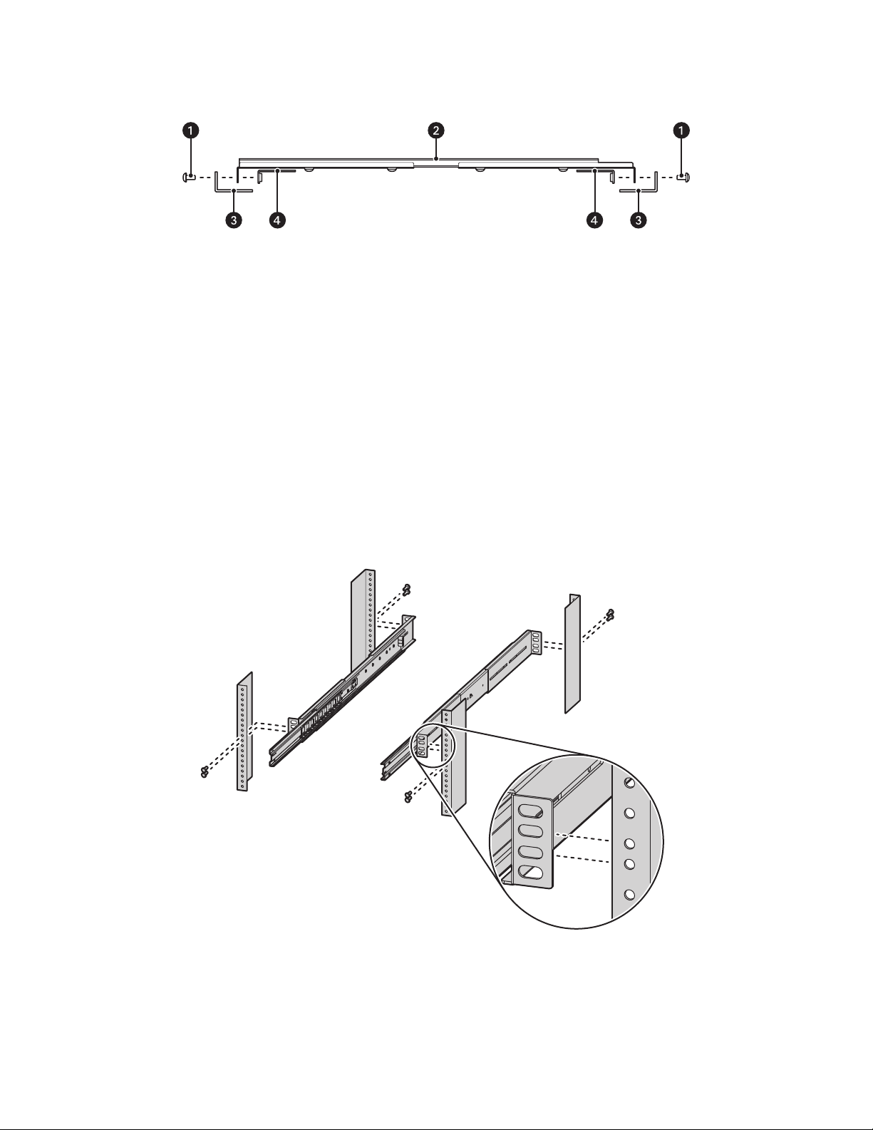
5. Mount the sliding brackets with attached L-shaped brackets to the rack, back to back as shown in Figure 11. Figure 10 shows the assembly
items required for this step.
Figure 10. Support Rail Assembly
ì
M5 x 8L-H2.5 Round Head Nickel Screws
î
Sliding Bracket with Attached L-shaped Brackets
ï
Rack
ñ
L-Shaped Plate Nut
NOTE: The sliding brackets with attached L-shaped brackets are identical and may be used on either side of the rack.
a. Position the ear of the front L-shaped bracket and an L-shaped plate nut against the inside front of the equipment rack. Align the two
center holes in the ear of the L-shaped bracket and L-shaped plate nut with the holes in the rack.
b. Insert and tighten two M5 x 8L-H2.5 round head nickel screws (supplied).
c. Slide the rear-facing L-shaped bracket to the back of the equipment rack.
d. Attach the rear L-shaped bracket and another L-shaped plate nut to the rack, as described in previous steps.
e. Repeat the previous steps for the opposing side of the rack.
Figure 11. Attaching the Brackets to the Rack
6. Tighten the M4 x 6L-H2.5 round head nickel screws attaching the L-shaped brackets to the sliding brackets that were previously left
untightened.
C4687M-C (7/13) 17
Page 18

7. Slide the SM5200 with attached chassis brackets into the sliding brackets. This step may require two people to lift and slide the unit into
place.
Figure 12. Installing the Unit in the Rack
NOTE: Align the chassis brackets with the first slot on the sliding brackets when installing the unit (refer to Figure 13). This ensures that
the unit properly slides in and out of the rack. To remove the unit from the rack, pull it out of the rack until the sliding bracket locks into
place, and then press the release lever on both chassis brackets.
Figure 13. Aligning the Chassis Bracket and the Sliding Bracket
8. Insert and tighten two M5 x 8L-H2.5 round head nickel screws above and below the chassis handles to secure the unit in the rack.
WARNING: When sliding the unit out, take care to prevent it from falling out of the rack.
18 C4687M-C (7/13)
Page 19

INSTALLING THE DRIVE ARRAY
The unit comes with two solid state drives (SSD) containing the operating system and user settings in RAID 1 (Redundant Array of Independent
Disks) configuration. The unit also comes with up to four additional hard disk drives (HDDs) for storing video for quick export in JBOD (Just a
Bunch of Disks) or RAID 5 configuration depending on the unit make and model.
The two SSDs must be installed in drive slots 1 and 2. Their RAID 1 configuration ensures that a single SSD failure will not affect the system’s
uptime or performance.
HDDs must be installed in drive slots 3 through 6. If installing fewer than three drives, they operate in JBOD configuration. If installing three or
more drives, they operate in RAID 5 configuration, ensuring that the failure of any one of the hard drives will not interrupt unit operation or result
in data loss.
NOTE: The minimum configuration for an internal RAID 5 is three hard disk drives. One drive in RAID 5 configuration is used for parity, reducin g
net storage capacity by the value of one drive.
WARNINGS:
• After replacing a failed drive in a RAID configuration, the unit must rebuild the drive before it returns to service. If a second hard drive
in the array fails before the first failed hard drive has completed the rebuild process, the array will go offline and data loss will occur.
• The SSDs containing the operating system must be installed first and are not hot-swappable.
INSTALLING THE DRIVE CARRIERS
Install the drives supplied with the unit in the front of the chassis. Drives and drive bays are both numbered 1to 6. Place drives in their
corresponding bays in numerical order.
Each drive is already mounted in its own drive carrier so you can easily install and remove a drive, even while the unit is operating.
Figure 14. Numbered Hard Drive Bays for SM5200
ì
Drive Bay 1: SSD
î
Drive Bay 2: SSD
ï
Drive Bay 3: HDD
ñ
Drive Bay 4: HDD
ó
Drive Bay 5: HDD
r
Drive Bay 6: HDD
C4687M-C (7/13) 19
Page 20

To install the hard drive carriers:
NOTE: Make sure you protect the unit and its components from improper handling and ESD. Refer to the Safe Handling of Hard Drives document
for more information.
1. Unlock and open the bezel.
Figure 15. Opening the Bezel
2. Install each drive carrier as follows:
a. Open the drive latch (grasp the right side of the latch and pull it to the left).
b. With the drive latch open, slide the drive carrier gently into the designated bay until it stops.
Figure 16. Installing a Drive Carrier
c. Close the drive carrier latch.
Figure 17. Closing and Locking a Drive Carrier
3. After inserting all drives, close and lock the bezel.
CONNECTING THE POWER SUPPLY
1. Connect the power cord to the power supply connector.
2. Connect the other end of the power cord to the appropriate 110/220 VAC power source.
NOTE: If you are connecting the unit to a uninterruptable power supply (UPS), refer to Appendix A: Installing an Uninterruptible Power Supply on
page 28.
20 C4687M-C (7/13)
Page 21

CONNECTING TO THE NETWORK
SECONDARY
NETWORK
The SM5200 comes equipped with primary and secondary network interfaces, allowing the unit to act as a gateway to the Endura network.
• The primary network interface connects to your private Endura network, and it is the interface over which all optional system manager
services operate. You must configure the primary interface.
• The secondary network interface connects to an alternate network, providing access to Endura from outside the private network. Before
proceeding, ensure that your IT department has reserved and issued the appropriate IP address range for the Endura system.
To configure your network interfaces, log on to the SM5200’s Web configuration application; for more information, refer to the SM5200 System
Manager Configuration manual.
NOTE: Connect the unit to a Gigabit Ethernet network. Always use standard Cat5e or better UTP cabling.
To connect the unit to a network:
1. Connect an Ethernet cable to a network connection on the rear of the unit.
2. Connect the other end of the network cable to an available ethernet port.
Figure 18. Network Cable Connection
C4687M-C (7/13) 21
Page 22

Startup and Shutdown
STARTING UP THE UNIT
1. Unlock and open the bezel.
2. Press the power button. The power indicator glows.
3. Close and lock the bezel.
4. Check indicators:
• The power indicator should glow blue. (If the bezel is open, the power indicator glows white.)
• The unit status indicator should glow solid green after the unit starts up.
• The network status indicator on the front panel shows the network connection speed and status.
Figure 19. Starting Up the Unit
ì
Power Button/Power Indicator
SHUTTING DOWN THE UNIT
You can shut down the unit locally using the power button or remotely using Endura Utilities.
PERFORMING A REMOTE SHUTDOWN
1. Open Endura Utilities.
2. Select SM5200 in the left pane of the System Attributes tab.
3. Right-click the unit in the right pane, point to Scripts, and then select One-Time Script.
4. Type shutdown -h now in the Script Command field.
5. Click OK; a confirmation prompt appears.
6. Click Yes.
PERFORMING A LOCAL SHUTDOWN
1. Unlock and open the bezel.
2. Press and hold the power button until the unit shuts down.
3. Close and lock the bezel.
22 C4687M-C (7/13)
Page 23

RESTARTING THE UNIT
1. Open a Web browser.
2. Type the unit’s IP address or host name in the address bar.
3. Log on to the SM5200 Configuration Interface with administrative credentials.
4. Click System Tools.
5. Click Restart SM5200.
C4687M-C (7/13) 23
Page 24

Troubleshooting
If the following instructions fail to solve your problem, contact Pelco Product Support at 1-800-289-9100 (USA and Canada) or +1-559-292-1981
(international) for assistance.
NOTE: Do not try to repair the unit yourself. Leave maintenance and repairs to qualified technical personnel.
Problem Possible Causes Suggested Solution
The unit is not ready. Power turned off. Check that the power indicator is lit.
The unit is not ready for operation
after software update.
The unit status indicator is red. Unit fan failure. Replace the failed fan.
The unit status indicator is red
and the power supply alarm
sounds.
The unit status and hard drive
indicators are red and the unit
alarm sounds.
The unit does not finish booting
following a system migration.
Video performance drops
significantly for one or more
cameras.
Faulty cable connections. Check all leads, plugs, contacts, and connections.
Network connectivity issues. Contact your network administrator.
Voltage failure while applying
software update.
Power supply failure.
Temperature exceeds specifications
(internal or external).
Power loss to either power supply. Check each power supply, line voltage, and the UPS.
Power supply module failure. Replace the failed power supply.
Hard drive failure. Replace the failed hard drive.
The flash drive used for system
migration contains a master boot
record.
The flash drive used for system
migration was removed while the
unit was rebooting.
A synchronization issue between the
system manager and client might
have forced the stream into I-frameonly mode.
Replace the unit and have it checked by Pelco.
Check power supplies.
Check all fans; check the external temperature.
Remove the flash drive and restart the system.
Remove the flash drive, connect a keyboard to any of the unit’s
USB 2.0 ports, and then press any key.
Perform a hard reset on the system.
Reconnect to the stream, either by accessing the camera or
reloading the page on which you are viewing video.
24 C4687M-C (7/13)
Page 25

Specifications
SYSTEM
Processor 2nd Generation Intel® Core™ i7
Operating System Embedded Linux
User Interface Web Interface
Internal System Drives 6, 3.5-inch hard drive bays
Internal Storage Capacity
Operating System SSD RAID1*
Export Footage Storage Up to 12 TB in RAID 5
USB Ports
Front 1 USB 2.0
Rear 2 USB 2.0; 2 USB 3.0
*
Drives 1 and 2 are SSD drives operating in a RAID 1 array, mirroring the operating system.
†
Drives 3 to 6 are HDDs operating in a JBOD or RAID 5 configuration, depending on the number of discs in the array.
REMOTE CLIENT PC REQUIREMENTS
Supported Web Browsers Microsoft® Internet Explorer® 9 and above, Mozilla® Firefox® 8‡ and above, and Google Chrome™ version
‡
To access the system manager over IPv6 using Mozilla Firefox, the IPv6 address must be resolved through a DNS server or through the host file
on the local machine.
NETWORK
Interface 2 Gigabit Ethernet RJ-45 ports (1000Base-T)
®
†
16 and later.
PELCO WEB VIEWER COMPATIBILITY
Live View and playback/export features of the Pelco Web Viewer are not available from all Endura components. The table below lists the Pelco
Web Viewer features available from legacy cameras, current cameras, encoders, and recorders.
Device Live View Playback/Export
ENC5308/ENC5316
Through DVR53xx
NVR5000 N/A
NVR5100 N/A
NET53xxT •
NET54xxT •
NSM5200 N/A •
®
Sarix
UDI5000-CAM •
UDI5000-MTRX •
•
•
Endura Component Compatibility Notes
The SM5200 is compatible with existing and legacy Endura system components. Please note the following minimum software versions required:
Current Endura Components
• WS5200/WS5070: Must be upgraded to version 2.5.3.10286 or later to configure operator access to the Pelco Web Viewer.
• WS5000/WS5050/WS5060: Compatible with the SM5200 when used as a replacement for the SM5000. The user interface must be
upgraded to leverage the Web browser and transcoding capabilities of the SM5200.
• VCD5202: No compatibility restrictions. When using the VCD5202 with the KBD5000 keyboard, user passwords are restricted to
alphanumeric characters unless using a USB keyboard to log on.
• WS5200-MAP: No compatibility restrictions.
• NET5402R-HD: No compatibility restrictions.
C4687M-C (7/13) 25
Page 26

Legacy Endura Components
• WS5000/WS5060/WS5070: There are no compatibility restrictions when the SM5200 is used as a replacement for the SM5000. You must
upgrade to the WS5200/WS5070 to utilize the SM5200’s remote access capabilities.
• GW5000/NET5301TC: No compatibility restrictions. The GW5000 and NET5301TC can continue to be used for their respective functions
independently of the SM5200’s remote access capabilities.
• VCD500x: User passwords must be alphanumeric unless a USB keyboard is used to log on.
• NET5301R: No compatibility restrictions
• NVR51xx/SEB51xx: No compatibility restrictions. Footage on NVR51xx units cannot be queried for remote search, playback, or export
from the SM5200.
• DVR53xx: No compatibility restrictions. Footage on DVR53xx cannot be queried for search, playback, or export from the SM5200.
™
• DVR51xx: No compatibility restrictions in Endura Enabled
environments. Footage on Endura Enabled DVR51xx units cannot be queried for
search, playback, or export from the SM5200.
FRONT PANEL INDICATORS/FUNCTIONS
Buttons Power
Indicators
Power Blue
Unit Status Green, amber, red
Primary Network Green, amber, red
Secondary Network Green, amber, red
Software Status Green, amber, red
Drive Status (6X) Green, amber, red
POWER
Power Input 100 to 240 VAC, 50/60 Hz, autoranging
Power Supply Internal
Power Consumption Operating Maximum
110 VAC, 60 Hz 223.0 W, 2.03 A, 761.4 BTU/H
115 VAC, 60 Hz 215.5 W, 1.87 A, 735.7 BTU/H
220 VAC, 60 Hz 204.1 W, 0.93 A, 696.8 BTU/H
Power Cords 1 power cord based on country designation
NOTE: Units shipped to China do not contain power cords. A CCC approved power cord must be used to
power this equipment when used in China.
ENVIRONMENTAL
Operating Temperature 10° to 35°C (50° to 95°F)
Storage Temperature –40° to 65°C (–40° to 149°F)
Operating Humidity 20 to 80%, noncondensing
Maximum Humidity Gradient 10% per hour
Operating Altitude –15 to 3,048 m (–50 to 10,000 ft)
Operating Vibration 0.25 G at 3 Hz to 200 Hz at a sweep rate of 0.5 octave/minute
NOTE: The temperature at the unit air intake can be significantly higher than room temperature. Temperature is affected by rack configuration,
floor layout, air conditioning strategy, and other issues. To prevent performance failure and unit damage, make sure the temperature at the unit is
continuously within the operating temperature range.
PHYSICAL
Dimensions 50.8 x 43.4 x 8.9 cm
(20" D x 17.1" W x 3.5" H)
Mounting Rack or desktop (feet)
Weight Unit
SM5200-03 17.1 kg (37.8 lb)
SM5200-12 18.9 kg (41.8 lb)
26 C4687M-C (7/13)
Page 27

Standards/Organizations
• Pelco is a member of the MPEG-4 Industry Forum
• Pelco is a member of the Universal Plug and Play (UPnP) Forum
• Pelco is a member of the Universal Serial Bus (USB) Implementers Forum
• Pelco is a contributor to the International Standards for Organization/ Electrotechnical Commission (ISO/IEC) Joint Technical Committee 1
(JTC1), “Information Technology,” Subcommittee 29, Working Group 11
• Compliance, ISO/IEC 14496 standard (also known as MPEG-4)
• Compliance, International Telecommunication Union (ITU) Recommendation G.711, “Pulse Code Modulation (PCM) of Voice Frequencies”
C4687M-C (7/13) 27
Page 28

Appendixes
UPS
POWER SOURCE
INPUT POWER
USB
OUTPUT POWER
APPENDIX A: INSTALLING AN UNINTERRUPTIBLE POWER SUPPLY
You should connect each unit to a UPS (not supplied). UPS units maintain a limited amount of backup battery power if the main power fails.
WARNING: While most UPS units can be used to supply backup battery power it is recommended that you connect the unit to a SmartUPS
from APC. The SmartUPS signals the unit to begin a graceful shutdown if the standby power in the UPS falls below a certain threshold.
To connect communication and power from the UPS to the unit (refer to Figure 20):
1. Shut down the unit if it is on.
2. Connect a power cord from the unit power supply to a standard wall socket.
3. Connect a power cord from the UPS to a standard wall socket or other power source.
4. Connect a USB cable from the UPS to a USB connector on the unit.
5. Power up the UPS.
6. Power up the unit (refer to Startup and Shutdown on page 22 for more information).
Figure 20. Connecting a UPS
28 C4687M-C (7/13)
Page 29

APPENDIX B: MIGRATING DATA FROM AN SM5000
For a quick and seamless transition to a new system manager, you can transfer data and settings from your existing SM5000 to a new SM5200.
NOTES:
• You must configure the network interface and DHCP settings on the SM5200 to match the settings from the SM5000 before performing
the migration process, or you will lose these settings in the migration process.
• Data migration requires a flash drive with an empty boot record and a Windows-based client on the Endura network. It is recommended
that you use the Pelco flash drive included with your SM5200 for data migration.
• Data migration requires Endura Utilities version 2.3.3 or later. You can download the current version from www.Pelco.com.
• Data migration does not include primary network interface settings or settings for features new and specific to the SM5200. You must
manually configure these settings.
• Do not replace your existing system manager until your new SM5200 is fully configured. Refer to the SM5200 System Manager
Configuration manual for help configuring your SM5200.
• Only the admin user can log on to the SM5200. If the admin user exists before migration, the user will log on to the SM5200 using the
existing account password. If this admin user does not exist before migration, the admin user will log on using the default password.
To transfer Endura data and settings from a SM5000 to a SM5200:
1. Connect your Pelco Flash Drive to a Windows-based client on the Endura network.
2. Open Endura utilities.
3. Right-click SM5000 in the System Attributes tab.
4. Select SM Backup.
5. Select the flash drive as the backup location and click OK. This creates a folder on the flash drive with the name of the IP address of the
SM5000 containing the UtilitiesBackup.tgz file.
6. Copy the UtilitiesBackup.tgz file to the root directory of the flash drive.
7. Remove the flash drive from the client computer and connect it to the SM5200.
8. Turn on the SM5200. After a short boot process, the four lights on the right side of the unit’s front panel (unit status, network port 1,
network port 2, and software status) turn solid amber, indicating that the system is importing the UtilitiesBackup.tgz file. This process might
take several minutes.
9. Remove the flash drive when the software status light turns off, indicating that the migration process is complete. The SM5200 restarts
30 seconds after the migration process has completed. Remove the flash drive within 30 seconds of the completed migration process, or
once the unit has fully rebooted; do not remove the flash drive during the boot process.
NOTE: Upon completing the data migration process, the SM5200 creates a file called .sm5000-migrated in the root directory of the flash drive,
preventing the SM5200 from attempting to import the UtilitiesBackup.tgz file multiple times. If data fails to migrate or you want to reuse the
flash drive to transfer data to another SM5200, delete the .sm5000-migrated file from the flash drive.
Data migration is complete. Upon restarting, configure the network interfaces and other settings specific to the SM5200. Refer to the SM5200
System Manager Configuration manual for additional information.
C4687M-C (7/13) 29
Page 30

30 C4687M-C (7/13)
Page 31

PRODUCT WARRANTY AND RETURN INFORMATION
WARRANTY
Pelco will repair or replace, without charge, any merchandise proved defective in
material or workmanship for a period of one year after the date of shipment.
Exceptions to this warranty are as noted below:
• Five years:
– Fiber optic products
– Unshielded Twisted Pair (UTP) transmission products
– CC3701H-2, CC3701H-2X, CC3751H-2, CC3651H-2X, MC3651H-2, and
MC3651H-2X camera models
• Three years:
– FD Series and BU Series analog camera models
– Fixed network cameras and network dome cameras with Sarix
– Sarix thermal imaging products (TI and ESTI Series)
– Fixed analog camera models (C20 Series, CCC1390H Series, C10DN Series,
and C10CH Series)
– EH1500 Series enclosures
– Spectra
– Spectra HD dome products
– Camclosure
®
IV products (including Spectra IV IP)
®
IS Series integrated camera systems
– DX Series video recorders (except DX9000 Series which is covered for a
period of one year), DVR5100 Series digital video recorders, Digital Sentry
Series hardware products, DVX Series digital video recorders, and NVR300
Series network video recorders
®
– Endura
– Genex
Series distributed network-based video products
®
Series products (multiplexers, server, and keyboard)
– PMCL200/300/400 Series LCD monitors
– PMCL5xxF Series and PMCL5xxNB Series LCD monitors
– PMCL5xxxBL Series LED monitors
• Two years:
– Standard varifocal, fixed focal, and motorized zoom lenses
– DF5/DF8 Series fixed dome products
®
– Legacy
– Spectra III
Series integrated positioning systems
™
, Spectra Mini, Spectra Mini IP, Esprit®, ExSite®, ExSite IP, and
PS20 scanners, including when used in continuous motion applications
– Esprit Ti and TI2500 Series thermal imaging products
– Esprit and WW5700 Series window wiper (excluding wiper blades)
– CM6700/CM6800/CM9700 Series matrix
– Digital Light Processing (DLP
®
) displays (except lamp and color wheel). The
lamp and color wheel will be covered for a period of 90 days. The air filter is
not covered under warranty.
®
technology
•Six months:
– All pan and tilts, scanners, or preset lenses used in continuous motion
applications (preset scan, tour, and auto scan modes)
Pelco will warrant all replacement parts and repairs for 90 days from the date of
Pelco shipment. All goods requiring warranty repair shall be sent freight prepaid
to a Pelco designated location. Repairs made necessary by reason of misuse,
alteration, normal wear, or accident are not covered under this warranty.
Pelco assumes no risk and shall be subject to no liability for damages or loss
resulting from the specific use or application made of the Products. Pelco’s liability
for any claim, whether based on breach of contract, negligence, infringement of
any rights of any party or product liability, relating to the Products shall not exceed
the price paid by the Dealer to Pelco for such Products. In no event will Pelco be
liable for any special, incidental, or consequential damages (including loss of use,
loss of profit, and claims of third parties) however caused, whether by the
negligence of Pelco or otherwise.
The above warranty provides the Dealer with specific legal rights. The Dealer may
also have additional rights, which are subject to variation from state to state.
If a warranty repair is required, the Dealer must contact Pelco at (800) 289-9100 or
(559) 292-1981 to obtain a Repair Authorization number (RA), and provide the
®
following information:
1. Model and serial number
2. Date of shipment, P.O. number, sales order number, or Pelco invoice number
3. Details of the defect or problem
If there is a dispute regarding the warranty of a product that does not fall under
the warranty conditions stated above, please include a written explanation with
the product when returned.
Method of return shipment shall be the same or equal to the method by which the
item was received by Pelco.
RETURNS
To expedite parts returned for repair or credit, please call Pelco at (800) 289-9100
or (559) 292-1981 to obtain an authorization number (CA number if returned for
credit, and RA number if returned for repair) and designated return location.
All merchandise returned for credit may be subject to a 20 percent restocking and
refurbishing charge.
Goods returned for repair or credit should be clearly identified with the assigned
CA or RA number and freight should be prepaid.
Revised 10-9-12
The materials used in the manufacture of this document and its components are compliant to the requirements of Directive 2002/95/EC.
This equipment contains electrical or electronic components that must be recycled properly to comply with Directive 2002/96/EC of the European Union
regarding the disposal of waste electrical and electronic equipment (WEEE). Contact your local dealer for procedures for recycling this equipment.
REVISION HISTORY
Manual # Date Comments
C4687M 6/12 Original version.
C4687M-A 10/12 Updated system migration process.
C4687M-B 6/13 Updated system migration process.
Pelco, the Pelco logo, and other trademarks associa ted with Pelco products referred to in this publication are trademarks of Pelco, Inc. or its affilia tes. © Copyright 2012, Pelco, Inc.
ONVIF and the ONVIF logo are trademarks of ONVIF Inc. All other product names and services are the property of their respective compan ies. All rights reserved.
Product specifications and availability are subject to change without notice.
Page 32

Pelco by Schneider Electric 3500 Pelco Way Clovis, California 93612-5699 United States
USA & Canada Tel (800) 289-9100 Fax (800) 289-9150
International Tel +1 (559) 292-1981 Fax +1 (559) 348-1120
www.pelco.com www.pelco.com/community
 Loading...