

Page 1
®
SB26C / SB26D
Series Simulated Domes
Installation/Operation Manual
C1403M - 2/94
Pelco • 3500 Pelco Way, Clovis, CA 93612-5699 • USA • (800) 289-9100 or (1-559) 292-1981
FAX (800) 289-9150 or (1-559) 292-3827
Page 2

TABLE OF CONTENTS
Section Page
1.0 SCOPE ..............................................................................................................................................1
1.1 DESCRIPTION .........................................................................................................................1
1.2 WARNINGS ..............................................................................................................................1
2.0 INSTALLATION..................................................................................................................................2
2.1 MOUNTING ..............................................................................................................................2
2.2 CAMERA MOUNTING (Model SB26C Only) ............................................................................2
2.2.1 CONDUCTOR REQUIREMENTS .................................................................................2
3.0 CARE AND MAINTENANCE .............................................................................................................3
4.0 SERVICE AND REPAIR ....................................................................................................................3
4.1 RECOMMENDED EQUIPMENT AND TOOLS .........................................................................3
4.2 SERVICE TIPS .........................................................................................................................3
5.0 EXPLODED ASSEMBLY DIAGRAM .................................................................................................4
6.0 MECHANICAL PARTS LIST .............................................................................................................. 5
7.0 MODELS ........................................................................................................................................... 5
7.1 SPECIFICATIONS ....................................................................................................................5
8.0 WARRANTY AND RETURN INFORMATION ....................................................................................6
LIST OF ILLUSTRATIONS
Figure Page
1 SB26 Series Dimension Drawing ....................................................................................................1
2 SB26 Series Enclosure Exploded Assembly Diagram ....................................................................4
REVISION HISTORY
Manual # Date Comments
C1403M 2/94 Original version.
8/96 Updated part numbers in Section 6.0, Mechanical Parts List. Updated
dimension drawing.
®Pelco and the Pelco logo are registered trademarks of Pelco.
©Copyright 1996, Pelco. All rights reserved.
ii Pelco Manual C1403M (2/94)
Page 3
INSTALLATION/OPERATION MANUAL
Model SB26C AND SB26D
SIMULATED DOMES
1.0 SCOPE
The information contained in this manual covers the
SB26 Series of simulated domes.
1.2 WARNINGS
Prior to installation and use of this product, the following WARNINGS should be observed.
1. Installation and servicing should be done by Qualified Service Personnel and conform to all local
codes.
1.1 DESCRIPTION
Pelco's SB26 Series is a series of simulated discreet
indoor enclosures. The SB26D is a “dummy” dome
only, and the SB26C is equipped with a clear viewing
slot and fixed camera mount for fixed camera applications.
Design considerations were engineered into this series of discreet domes to assure ease of service and
installation.
2. This unit is specifically designed for indoor use
only and it must not be installed where exposed to
rain and moisture.
3. Only use replacement parts recommended by
Pelco.
Please thoroughly familiarize yourself with the information in this manual prior to installation and operation.
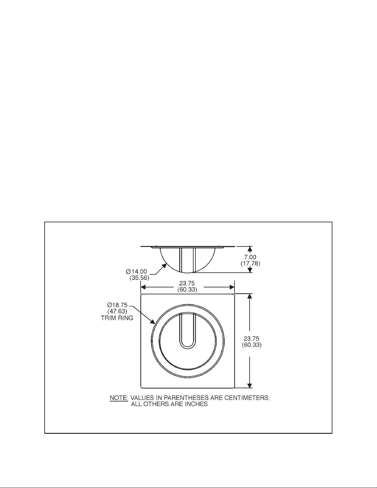
Figure 1. SB26 Series Dimension Drawing
Pelco Manual C1403M (2/94) 1
Page 4

2.0 INSTALLATION
2.2.1 Conductor Requirements
CAUTION: Make certain that the mounting
surface is capable of supporting the full load of
the retaining plate, dome, camera mount and
camera.
Handle the lower dome with care so as not to scratch or
fingerprint the viewing window.
2.1 MOUNTING
The SB26 Series of discreet domes can be installed by
performing the following steps:
1. Place the retaining plate in a 2' x 2' ceiling tile
opening. Make sure it rests securely on the “TBar”.
2. Install the guide wires to the “eye” bolt on the
top of the unit and tighten sufficiently to ensure
the retaining plate does not sag.
2.2 CAMERA MOUNTING
(Model SB26C Only)
Install the camera on the camera mount and position
the camera.
If a camera is used with the SB26C, the following can
be used as guidelines for determining the maximum
wire lengths for a hard-wire system.
Camera Wire Length (120 VAC Camera @ vA)
Maximum Cable Distance
Cable Size 3 vA 6 vA 10 vA
14 Awg 87,466 43,733 26,240
16 Awg 54,830 27,415 16,449
18 Awg 34,548 17,274 10,364
20 Awg 21,715 10,857 6,514
Camera Wire Length (24 VAC Camera @ vA)
Maximum Cable Distance
Cable Size 3 vA 6 vA 10 vA
14 Awg 3,809 1,904 1,142
16 Awg 2,388 1,194 716
18 Awg 1,504 752 451
20 Awg 945 472 283
Coax Cable Distances
Cable Size Maximum Cable Distance
RG-59U 750 feet
RG-11U 1,800 feet
RG-6U 1,500 feet
2 Pelco Manual C1403M (2/94)
Page 5

3.0 CARE AND MAINTENANCE
4.0 SERVICE AND REPAIR
Regularly scheduled maintenance will prolong the
operational life and appearance of the equipment.
IMPORTANT: The lower dome of the SB26C
simulated domes is an optical surface. When
cleaning the surface of the dome and the viewing window, treat the surface as carefully as you
would a fine camera lens.
1. If dust or other debris accumulates on the inside
of the lower dome, remove with clean air pressure. Compressed air cans are available from photographic equipment dealers.
WARNING: Do not use water, liquid or spray
cleaners of any kind on coated inner surfaces
of the dome.
2. Clean the outer surface of the dome and the inner
surface of the viewing window with a nonabrasive cleaning cloth and antistatic cleaner that is
safe for use on acrylic plastics. Do not use kerosene or similar substances that can scratch the
surface.
4.1 RECOMMENDED EQUIPMENT
AND TOOLS
1. 7/16" end wrench
2. Screwdriver, flat blade, Phillips head
3. Pliers, long nose
4.2 SERVICE TIPS
Some common problems encountered with the use of
this product include mix-wiring, overloading, and using
the units for incorrect applications. Should a failure of
the unit occur, it is recommended that the following
procedures be used.
1. If the camera ceases to operate, check to insure
that there is proper voltage to the camera and proper
connection and termination of the video line.
2. If the simulated dome sags, make sure the secur-
ing cable is properly fitted.
Pelco Manual C1403M (2/94) 3
Page 6

5.0 EXPLODED ASSEMBLY DIAGRAM
Figure 2. SB26 Series Enclosure Exploded Assembly Diagram
4 Pelco Manual C1403M (2/94)
Page 7

6.0 MECHANICAL PARTS LIST
The following parts list corresponds to the exploded assembly diagram in Figure 2.
Item Quantity Description Part Number
11Tilt table (SB26C only) EM44004005PNT
21Tilt table base (SB26C only) EM44004006PNT
34Ball Stud Receiver PT180410001
41Dome (SB26C) 81410001-1
(SB26D) SB25D1000
51Tile plate (SB26C, SB26D) SB264100COMP
61Dome/ceiling rod (SB26C, SB26D) SB25D4001COMP
71Trim Ring SB262ASSY
83Wing nut ZH1/4-20NUTSW
91Eye bolt ZH1/4.20X2.0EYE
10 4 Washer ZH260X562X65C
7.0 MODELS
SB26C 14" diameter simulated dome. Black
opaque lower dome has clear viewing window. Fixed camera mount included. (UL)
SB26D 14" diameter simulated dome. No view-
ing window or camera mount. (UL)
7.1 SPECIFICATIONS
Enclosure
Max. Camera/Lens
Length: 9.50" L x 2.50" W x 2.50" H
(including BNC connector)
Securing Means: 1/4-20 “eye” bolt for connection
of guide wire(s)
Construction:
Dome Retainer 0.080" aluminum/ABS trim ring
Dome Optically clear acrylic
Finish
(Mounting Plate): Semigloss white, self-textured
baked enamel
Environment: Indoor
Dimensions: See Figure 1
Camera Mount
Construction: 0.119" steel frame
Pan Rotation: 0-360° horizontal
Tilt Rotation: 90-180° vertical
Maximum Load: 7 lbs (3.15 kg)
Ambient Operating
Temperature Range: 50°F to120°F (-23°C to 49°C)
Weight 5 lbs (2.25 kg)
Pelco Manual C1403M (2/94) 5
Page 8

8.0 WARRANTY AND RETURN
INFORMATION
WARRANTY
Pelco will repair or replace, without charge, any merchandise proved
defective in material or workmanship for a period of one year after the date
of shipment.
Exceptions to this warranty are as noted below:
• Five years on FT/FR8000 Series fiber optic products.
• Three years on Genex
keyboard).
• Three years on Camclosure
CC3701H-2, CC3701H-2X, CC3751H-2, CC3651H-2X, MC3651H-2,
and MC3651H-2X camera models, which have a five-year warranty.
• Two years on standard motorized or fixed focal length lenses.
• Two years on Legacy
DF5/DF8 Series fixed dome products.
• Two years on Spectra
ing when used in continuous motion applications.
• Two years on Esprit
wiper blades).
• Eighteen months on DX Series digital video recorders, NVR300
Series network video recorders, and Endura
network-based video products.
• One year (except video heads) on video cassette recorders (VCRs).
Video heads will be covered for a period of six months.
• Six months on all pan and tilts, scanners or preset lenses used in
continuous motion applications (that is, preset scan, tour and auto scan
modes).
Pelco will warrant all replacement parts and repairs for 90 days from the
date of Pelco shipment. All goods requiring warranty repair shall be sent
freight prepaid to Pelco, Clovis, California. Repairs made necessary by
reason of misuse, alteration, normal wear, or accident are not covered
under this warranty.
Pelco assumes no risk and shall be subject to no liability for damages or
loss resulting from the specific use or application made of the Products.
Pelco’s liability for any claim, whether based on breach of contract,
negligence, infringement of any rights of any party or product liability,
relating to the Products shall not exceed the price paid by the Dealer to
Pelco for such Products. In no event will Pelco be liable for any special,
incidental or consequential damages (including loss of use, loss of profit
and claims of third parties) however caused, whether by the negligence
of Pelco or otherwise.
The above warranty provides the Dealer with specific legal rights. The
Dealer may also have additional rights, which are subject to variation from
state to state.
If a warranty repair is required, the Dealer must contact Pelco at (800) 2899100 or (559) 292-1981 to obtain a Repair Authorization number (RA),
and provide the following information:
1. Model and serial number
2. Date of shipment, P.O. number, Sales Order number, or Pelco invoice
number
3. Details of the defect or problem
If there is a dispute regarding the warranty of a product which does not fall
under the warranty conditions stated above, please include a written
explanation with the product when returned.
Method of return shipment shall be the same or equal to the method by
which the item was received by Pelco.
®
Series products (multiplexers, server, and
®
and fixed camera models, except the
®
, CM6700/CM6800/CM9700 Series matrix, and
®
, Esprit®, ExSite™, and PS20 scanners, includ-
®
and WW5700 Series window wiper (excluding
™
Series distributed
RETURNS
In order to expedite parts returned to the factory for repair or credit, please
call the factory at (800) 289-9100 or (559) 292-1981 to obtain an
authorization number (CA number if returned for credit, and RA number
if returned for repair).
All merchandise returned for credit may be subject to a 20% restocking
and refurbishing charge.
Goods returned for repair or credit should be clearly identified with the
assigned CA or RA number and freight should be prepaid. Ship to the
appropriate address below.
If you are located within the continental U.S., Alaska, Hawaii or Puerto
Rico, send goods to:
If you are located outside the continental U.S., Alaska, Hawaii or Puerto
Rico and are instructed to return goods to the USA, you may do one of the
following:
If the goods are to be sent by a COURIER SERVICE, send the goods to:
If the goods are to be sent by a FREIGHT FORWARDER, send the goods
to:
Service Department
Pelco
3500 Pelco Way
Clovis, CA 93612-5699
Pelco
3500 Pelco Way
Clovis, CA 93612-5699 USA
Pelco c/o Expeditors
473 Eccles Avenue
South San Francisco, CA 94080 USA
Phone: 650-737-1700
Fax: 650-737-0933
®
Pelco
3500 Pelco Way, Clovis, CA 93612-5699
(559) 292-1981 • (800) 289-9100
FAX (800) 289-9150 or (559) 292-3827
International customers call 1-559-292-1981 or
FAX 1-559-348-1120
Pelco, the Pelco logo, Camclosure, Esprit,
Genex, Legacy, and Spectra are registered
trademarks of Pelco.
Endura and ExSite are trademarks of Pelco.
© Copyright 1994, Pelco. All rights reserved.
(Product specifications subject to change
without notice.)
C1403M
6 Pelco Manual C1403M (2/94)
 Loading...