

Page 1
®
SB26/SB2600
Discreet
Surveillance
Domes
Installation/
Operation Manual
C1402M-B (2/98)
Pelco • 3500 Pelco Way, Clovis • CA 93612-5699 USA • www.pelco.com
In North America and Canada: Tel (800) 289-9100 or FAX (800) 289-9150
International Customers: Tel (1-559) 292-1981 or FAX (1-559) 348-1120
Page 2

CONTENTS
Section Page
1.0 GENERAL .................................................................................................. 5
1.1 IMPORTANT SAFEGUARDS AND WARNINGS ............................... 5
2.0 DESCRIPTION ..........................................................................................6
2.1 Models ................................................................................................ 7
3.0 INSTALLATION .......................................................................................... 8
3.1 CONDUCTOR AND CABLE REQUIREMENTS (ALL MODELS
EXCEPT SB26) .................................................................................8
3.2 WIRING INSTRUCTIONS ..................................................................8
3.3 MOUNTING INSTRUCTIONS ..........................................................13
3.3.1 Fixed Ceiling Mounting ..........................................................13
3.3.2 Dropped Ceiling, Tile Replacement Mounting ....................... 14
3.3.3 Camera/Lens Installation ....................................................... 15
3.4 CONNECTOR ASSEMBLY ............................................................... 16
3.5 J-BOX INSTALLATION ...................................................................... 17
3.6 ADJUSTMENTS ............................................................................... 19
4.0 MAINTENANCE ........................................................................................20
5.0 EXPLODED ASSEMBLY DIAGRAMS ...................................................... 21
6.0 SPECIFICATIONS .................................................................................... 29
7.0 WARRANTY AND RETURN INFORMATION ...........................................32
2 Pelco Manual C1402M-B (2/98)
Page 3

LIST OF ILLUSTRATIONS
Figure Page
1 SB2600 Wiring Diagram ....................................................................9
2 SB2600-SL Wiring Diagram .............................................................. 10
3 SB2600SL-PP Wiring Diagram ......................................................... 11
4 SB2600-PP Wiring Diagram .............................................................12
5 Fixed Ceiling Mounting .....................................................................13
6 Dropped Ceiling Mounting with Optional Mounting Kit ..................... 14
7“T-Bar” Clip Installation ......................................................................14
8 Attaching Camera/Lens to Tilt Table ................................................. 15
9 Attaching Dome to Drive Unit ............................................................ 15
10 Connector Assembly .........................................................................16
11 Attachment of J-Box to Back Box for Plenum Applications ...............18
12 Limit Stop Locations .........................................................................19
13 SB26 Exploded Assembly Diagram ..................................................21
14 SB2600 Series Pan/Tilt Exploded Assembly Diagram ......................22
15 SB2600 Hardware Exploded Assembly Diagram ............................. 25
16 SB26 Fixed Series Exploded Assembly Diagram .............................27
17 SB2600 Dimension Drawing ............................................................. 30
LIST OF TABLES
Table Page
A SB26 Exploded Assembly Parts List ................................................. 21
B SB2600 Series Pan/Tilt Exploded Assembly Parts List .................... 23
C SB2600 Hardware Exploded Assembly Parts List ............................26
D SB26 Fixed Series Exploded Assembly Mechanical Parts List ........ 28
E SB26 Fixed Series Exploded Assembly Associated Hardware
Parts List ...........................................................................................28
REVISION HISTORY
Manual # Date Comments
C1402M 9/94 Original Manual.
C1402M-A 9/95 Rev. A. Revised Section 4.4, Connector Assembly and
C1402M-B 8/96 Rev. B. Revised hardware configuration for SB2600
10/97 Changed manual to new format.
2/98 Revised Section 4.0, Maintenance. Changed manual
updated item no. 30, 45 and 46 on the SB2600 Series
mechanical parts list.
pan/tilt, changing spindle design. In addition, part No.
changed on items No. 6 and 29 on the SB2600 Series
mechanical parts list (Figure 15). Revised Sections 7.0
and 8.1, Mechanical Parts Lists, regarding dome part
numbers. Revised Sections 7.0 and 8.1, Mechanical
Parts Lists, regarding dome part numbers.
pagination.
Pelco Manual C1402M-B (2/98) 3
Page 4

(This page intentionally left blank.)
4 Pelco Manual C1402M-B (2/98)
Page 5
1.0 GENERAL
1.1 IMPORTANT SAFEGUARDS AND WARNINGS
CAUTION:
This device
is designed to operate at
24 volts AC power. Input
voltage must not exceed
28 volts or drop below 22
volts or else
DAMAGE TO
THE MOTORS WILL
OCCUR.
Should you
need technical assistance, please call (800)
289-9100.
Prior to installation and use of this product, the following WARNINGS should be
observed.
1. Installation and servicing should only be done by Qualified Service Personnel
and conform to all Local codes.
2. Unless the unit is specifically marked as a NEMA Type 3, 3R, 3S, 4, 4X, 6, or
6P enclosure, it is designed for indoor use only and it must not be installed
where exposed to rain and moisture.
3. Only use replacement parts recommended by Pelco.
4. After replacement/repair of this unit’s electrical components, conduct a resistance measurement between line and exposed parts to verify the exposed
parts have not been connected to line circuitry.
5. The installation method and materials should be capable of supporting four
times the weight of the enclosure, pan/tilt, camera and lens combination.
The product and/or manual may bear the following marks:
This symbol indicates that dangerous voltage constituting a
risk of electric shock is present within this unit.
This symbol indicates that there are important operating and
maintenance instructions in the literature accompanying this
unit.
CAUTION:
RISK OF
ELECTRIC SHOCK.
DO NOT OPEN.
TO REDUCE THE RISK OF ELECTRICAL SHOCK,
DO NOT REMOVE COVER. NO USER-
SERVICEABLE PARTS INSIDE. REFER SERVICING
TO QUALIFIED SERVICE PERSONNEL.
CAUTION:
Please thoroughly familiarize yourself with the information
in this manual prior to installation and operation.
Pelco Manual C1402M-B (2/98) 5
Page 6

2.0 DESCRIPTION
The SB26 is a discreet surveillance, low profile, hemisphere dome for CCD type
cameras designed for ease of installation, relocation, and service in fixed ceilings
or standard 2' x 2' (.61 m x .61 m) or 2' x 4' (.61 m x 1.22 m) false ceiling tiles. The
black opaque lower dome effectively conceals the camera while providing an inconspicuous viewing window. The dome is attached to the drive to keep the viewing
window and camera aligned.
To simplify installation even further, Pelco offers system packages with factory installed standard components from its regular product line. Options include a 24 VAC
pan/tilt with factory pre-wired feedthrough for all control functions (i.e., pan/tilt, motorized zoom lens, camera power [24 VAC] and video), continuous 360° pan rotation, and a position feedback package for presets.
The dome and camera assembly rotate at a speed of 24 degrees/second and offer
complete 360 degree surveillance coverage (SL series).
The back box is constructed of aluminum to meet fire code requirements for installation in open plenum ceilings.
6 Pelco Manual C1402M-B (2/98)
Page 7

2.1 MODELS
NOTE:
All of the models are listed
by Underwriters Laboratories Inc.
SB26 Drop ceiling discreet surveillance enclosure with black opaque
lower dome with 1 f-stop light loss and all aluminum back box
which mounts above the ceiling. (Camera mount supplied.)
(UL)
SB26-1 Same as SB26 except supplied with clear viewing slot for
virtually zero light loss. (UL)
SB26-2 Same as SB26 except supplied with mirrored lower dome with
2 f-stop light loss. (UL)
SB2600 This system package includes the SB26 black opaque dome
enclosure plus a 24 VAC pan/tilt factory assembled inside the
back box. It provides factory pre-wired feedthrough for all
control functions (i.e., pan/tilt, motorized zoom lens, camera
power [24 VAC] and video). All connections are made at the
input connector, eliminating wiring harnesses made in the
field. (CE, UL)
SB2600-PP Same as the SB2600, except this package features the factory
installed preset (PP) option. (CE, UL)
SB2600-SL Same as the SB2600, except this package features 360°
continuous pan rotation. (CE, UL)
SB2600SL-PP Same as the SB2600-SL with the addition of the preset (PP)
option. (CE, UL)
SB2601 Same as SB2600 except supplied with black opaque lower
dome with clear viewing slot for virtually zero light loss.
(CE, UL)
SB2601-PP Same as SB2601 except with preset (PP) option. (CE, UL)
SB2601-SL Same as SB2601 except supplied with 360° continuous pan
SB2601SL-PP Same as SB2601-SL except with preset (PP) option. (CE, UL)
SB2602 Same as SB2601 except supplied with mirrored lower dome,
SB2602-PP Same as SB2602 except with preset (PP) option.
SB2602-SL Same as SB2602 except supplied with 360° continuous pan
SB2602SL-PP Same as SB2602-SL except with preset (PP) option. (CE, UL)
rotation. (CE, UL)
with 2 f-stop light loss.
rotation. (CE, UL)
Pelco Manual C1402M-B (2/98) 7
Page 8

3.0 INSTALLATION
Save the shipping box and any inserts in case the unit must be returned for credit or
repair.
3.1 CONDUCTOR AND CABLE REQUIREMENTS (ALL MODELS EXCEPT SB26)
A minimum of 12 conductors plus coax is required, which includes common requirements for motorized zoom lens and camera AC power.
NOTE:
The following are cable
requirements. A relay box (RB24) is
available to extend the operating distance up to 13,000 feet (3962.4 m)
over 16 Awg wire.
Non-PP Models
12 Conductor 13 Conductor*
20 Awg 130 ft (39.62 m) 185 ft (56.38 m)
18 Awg 205 ft (62.48 m) 290 ft (88.39 m)
16 Awg 326 ft (99.36 m) 461 ft (140.51 m)
Models with PP
18 Conductor 19 Conductor*
20 Awg 130 ft (39.62 m) 185 ft (56.38 m)
18 Awg 205 ft (62.48 m) 290 ft (88.39 m)
16 Awg 326 ft (99.36 m) 461 ft (140.51 m)
*Using 2-conductor common.
Calculations are based on a 10% cable loss with both motors running.
3.2 WIRING INSTRUCTIONS
The SB2600 and SB2600-SL include a pan/tilt which is pre-wired for all control
functions (pan/tilt, motorized zoom lens, camera power [24 VAC], and video). All
connections are made to the input connector, eliminating the need for wiring harnesses made in the field. Wire the control cable according to the wiring diagram in
Figures 1 and 2 (non-PP models), or Figures 3 and 4 (PP models).
8 Pelco Manual C1402M-B (2/98)
Page 9
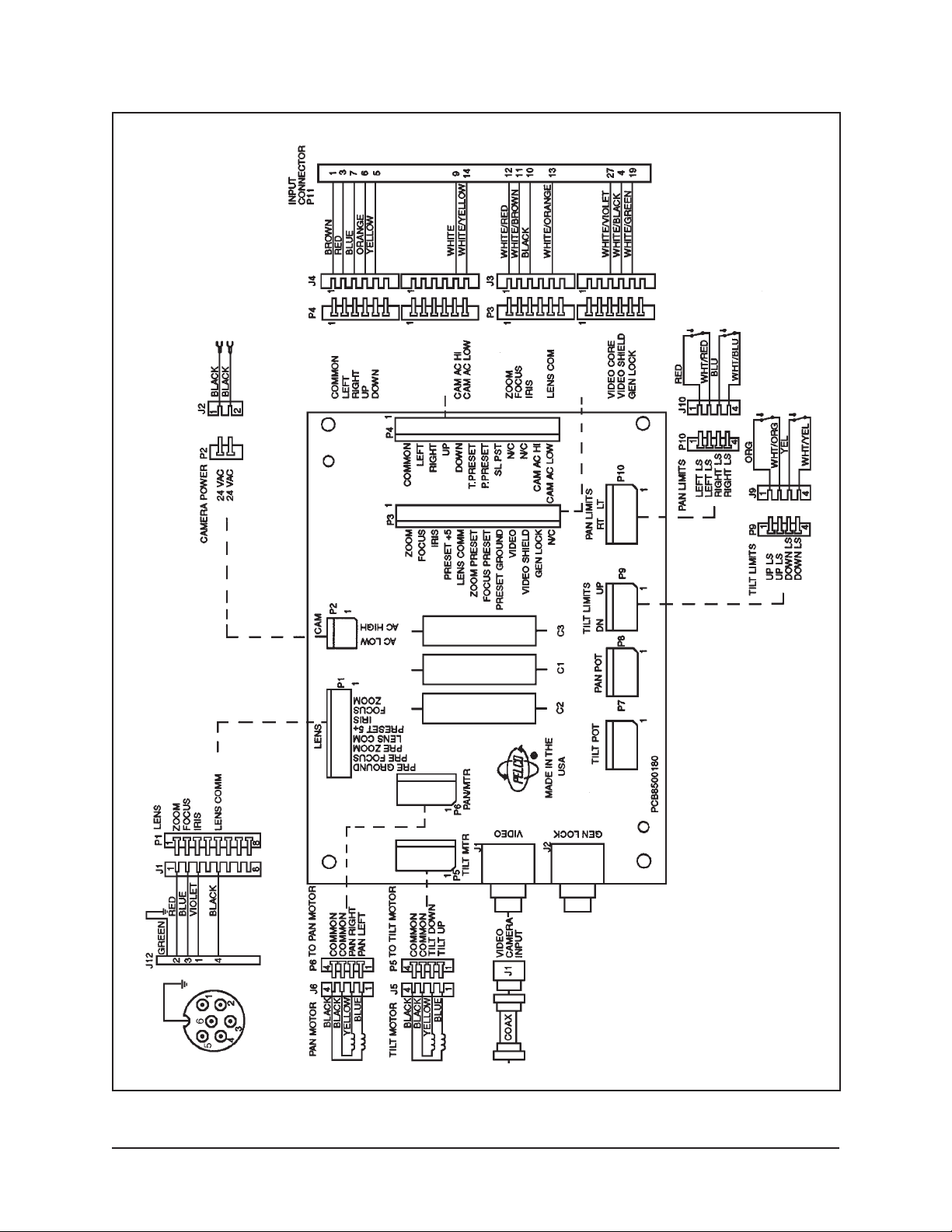
Figure 1. SB2600 Wiring Diagram
Pelco Manual C1402M-B (2/98) 9
Page 10
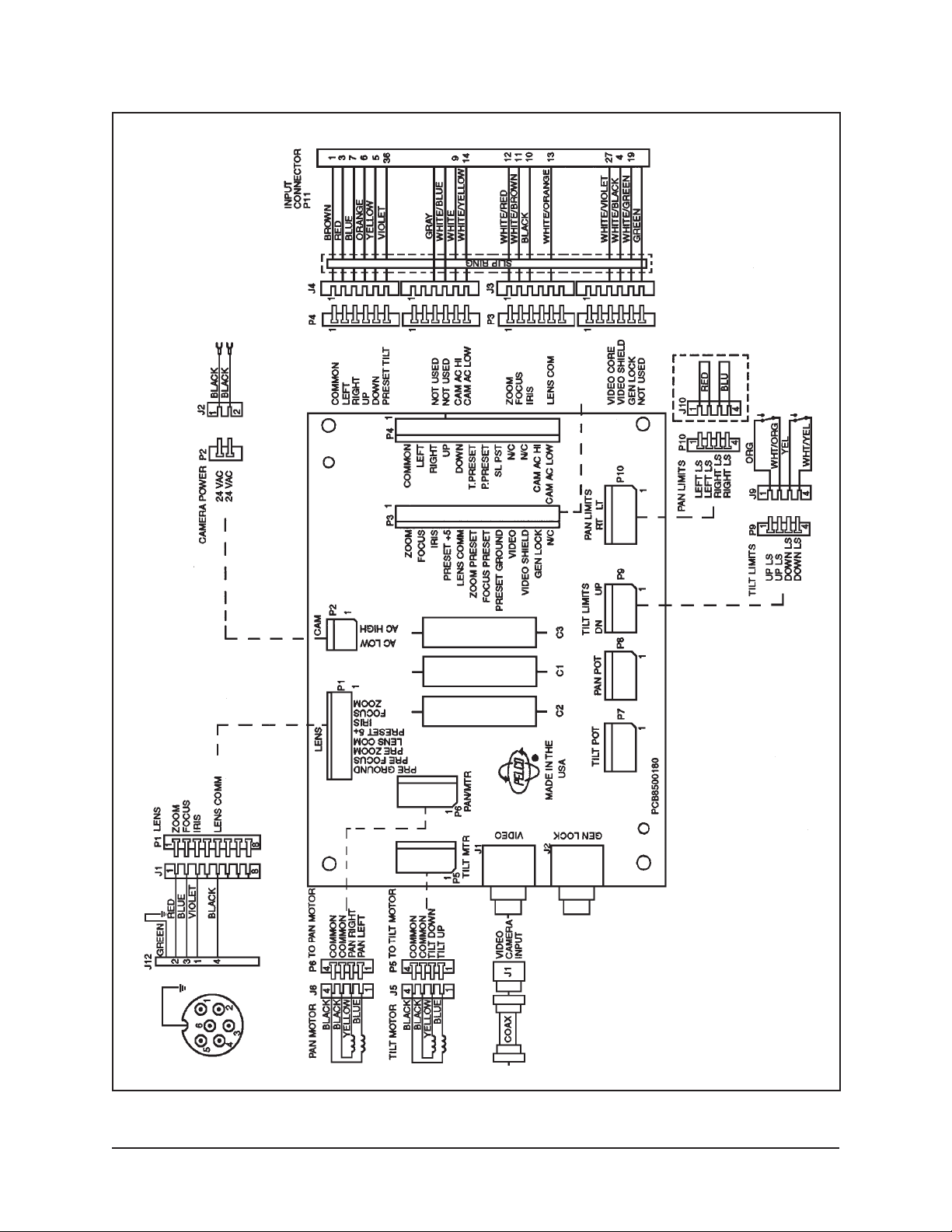
Figure 2. SB2600-SL Wiring Diagram
10 Pelco Manual C1402M-B (2/98)
Page 11

Figure 3. SB2600SL-PP Wiring Diagram
Pelco Manual C1402M-B (2/98) 11
Page 12

Figure 4. SB2600-PP Wiring Diagram
12 Pelco Manual C1402M-B (2/98)
Page 13

3.3 MOUNTING INSTRUCTIONS
Handle the lower dome with care so as not to scratch or get fingerprints on the
viewing window.
Determine the type of mounting desired. The enclosure can be mounted in a fixed
ceiling, or completely replace a standard 2' x 2' (.61 m x .61 m) ceiling tile.
3.3.1 Fixed Ceiling Mounting
To mount the enclosure directly into a fixed ceiling, perform the following steps
(refer to Figure 5):
1. Determine the location and direction of the enclosure. Ideally, the enclosure
cutout should be parallel and adjacent, or perpendicular, to any ceiling structure. Cut opening.
2. Remove the dome and drill holes into the side of the back box at the locations
where the fasteners need to be located.
3. Insert the back box into the opening. Using the appropriate fasteners (not
supplied), attach the back box to any adjacent structure through the drilled
holes in the box.
4. Mount the camera/lens onto the pan/tilt assembly with the camera/lens cen-
tered on the tilt table. Use the mounting screw provided.
5. Hook up camera power, video, and lens with the connectors supplied.
6. Ensure there is sufficient initial clearance between the camera/lens and dome
as you carefully attach dome to the drive unit as shown in Figure 9. Align the
four ball studs on the dome to the four ball stud receivers on the dome drive
and push the dome until a snapping sound occurs.
7. You are now ready to tilt the camera/lens up and down to check for clearance
between the lens and the dome. If proper clearance is not achieved the dome
will be dislodged from the dome drive. Also, pay attention to camera and wiring clearance up inside the drive.
Figure 5. Fixed Ceiling Mounting
Pelco Manual C1402M-B (2/98) 13
Page 14

3.3.2 Dropped Ceiling, Tile Replacement Mounting
To mount the enclosure into a dropped ceiling grid, perform the following steps
(refer to Figure 6):
IMPORTANT:
When installing the
enclosure in a 2' x 4' (.61 m x 1.22 m)
ceiling grid, cut the ceiling tile in half
and install an additional “T” bar for
support.
1. Determine the location for mounting the enclosure and remove the appropriate ceiling tile.
2. Remove trim ring and dome. Angle the back box through the grid opening and
set the box into the grid. If additional support of the back box is required,
thread the two (2) 1/4-20 eye bolts (supplied) into the two attachment points in
the top of the back box and hang the unit per local code.
3. From an opening in a grid adjacent to the beck box, apply the four (4) clips
supplied to the “T” bar for support (refer to Figure 7).
4. Mount the camera/lens onto the pan/tilt (fixed mount) assembly with the
camera/lens centered on the tilt table. Use the mounting screw provided.
5. Hook up camera power, video, and lens with the connectors supplied.
6. Attach the safety chain to the lower dome and install the dome.
7. Operate the pan/tilt to verify that there are no obstructions within the back box
or dome.
Figure 6. Dropped Ceiling Mounting with
Figure 7. “T-Bar” Clip Installation
Optional Mounting Kit
14 Pelco Manual C1402M-B (2/98)
Page 15

3.3.3 Camera/Lens Installation
Install the camera/lens that you have selected for use with the SB2600 Series dome
as follows:
NOTE:
Remove “shipping
bracket” at this time. Refer to Figure 14, item 65.
NOTE:
Fixed speed units must
have power on and you must be
able to activate the tilt functions.
Do
not rotate fixed speed dome
caves by hand. Damage will occur to the motors.
1. Loosen the 1/4-20 lens support fastener and slide lens support down (see
Figure 8).
2. Place camera/lens atop the tilt table and thread the provided 1/4-20 x 1/2-inch
fastener through the tilt table into the camera (see Figure 8). Snug the fastener
at this time to allow for camera/lens repositioning.
3. Connect camera power spade lugs, coax video cable and lens connector, paying
special attention to the routing of the cabling so as not to interfere with the
camera/lens swing.
4. Ensure there is sufficient initial clearance between the camera/lens and dome
as you carefully attach dome to drive unit as shown in Figure 9. Align the four
ball stud receivers on the dome drive and push dome until snapping sound
occurs. You are now ready to tilt the camera/lens combination up and down to
check for clearance between the lens and the dome. If proper clearance is not
achieved, the dome will be dislodged from the dome drive. Also pay attention
to camera and wiring clearance up inside the drive.
5. Adjust camera/lens and wire routing as necessary to achieve proper clearances. Always keep in mind that if the camera/lens can be balanced the unit
life will be extended.
6. After satisfactory clearances have been achieved, remove dome and tighten
all three camera/lens fasteners. The unit is now ready for operations test and,
if applicable, pan limit stop adjustments.
BALL STUD RECEIVERS
(1)
(3)
(2)
Figure 8. Attaching Camera/Lens to Tilt Table Figure 9. Attaching Dome to Drive Unit
Pelco Manual C1402M-B (2/98) 15
Page 16

3.4 CONNECTOR ASSEMBLY
14
59
15 10
22 16
28 23
33 29
37 34
Assemble the connector parts according to the instructions below. Detail B, below,
reflects the pin arrangement specific to all SB26/SB2600 Series. Refer to Figure 10
during assembly. For best results use an AMP style crimper when making the wire
to pin connection.
The instructions that follow apply to all AMP style connectors regardless of pin size
or pin number.
1. Slide the connector clamp assembly over the conductor cable. If the diameter
of the conductor cable is such that the rubber boot will slide over it easily then
slide the rubber boot onto the conductor cable at this time. If not, discard the
rubber boot.
2. Prepare the wires from the conductor cable as follows:
a. Strip at least 1" from the cable jacket to expose the wires. You may need
to strip more from the cable jacket if you have more wires.
b. Strip 1/8" from each wire.
c. Using an AMP style crimper, crimp the wires and their insulation to the
connector pins. Refer to Detail A in Figure 10.
3. Slide the connector pins into the appropriate holes in the connector body until
they snap into place. Refer to Figure 10 for correct pin arrangement, depending on model and options.
4. Push the connector clamp assembly (with boot, if used) toward the connector
body. Screw the clamp assembly onto the connector body, being careful not to
disturb the wires.
OR
5. To complete the assembly, attach the appropriate clamp with the screws provided and tighten.
1"
1/8"
FRONT VIEW
37-PIN
Figure 10. Connector Assembly
16 Pelco Manual C1402M-B (2/98)
Page 17

3.5 J-BOX INSTALLATION
For installations requiring full plenum rating, perform the following step:
Installations Requiring Conduit
When conduit must be run to the enclosure back box:
1. Attach the provided J-box to the top of the enclosure back box as shown in
Figure 11 using the supplied 6-32 screws.
2. Remove one of the knockouts from the J-box and attach the conduit to the
J-box (hardware not supplied).
3. Run the cabling through to the conduit.
4. Assemble the connector onto the end of the cable that is in the J-box, per
Section 3.4.
5. Place the J-box cover onto the J-box with two (2) 6-32 screws (supplied).
or
Installations Not Requiring Conduit
When conduit is not required at the enclosure back box:
1. Attach the provided J-box to the top of the enclosure back box as shown in
Figure 11 using the supplied 6-32 screws.
2. Remove the knockout from the edge of the J-box cover.
3. Run the assembled cable (see Section 3.4) into the J-box and place the cover
onto the J-box with the cable going through the knockout section of the cover.
Attach with 6-32 screws (supplied).
Pelco Manual C1402M-B (2/98) 17
Page 18

Figure 11. Attachment of J-Box to Back Box for Plenum Applications
18 Pelco Manual C1402M-B (2/98)
Page 19

3.6 ADJUSTMENTS
CAUTION:
Do not attempt to adjust limit stops
when the pan/tilt is in operation. Damage to the
equipment can result.
not
operate pan/tilt with-
Do
out limit stops.
Do not
remove or repo-
sition fixed limit stop.
DAMAGE WILL OCCUR.
Note the SL models are
supplied without pan limit
stops, therefore, no adjustments are necessary.
To adjust the pan limits, perform the following steps. Refer to Figure 12 for limit stop
locations. Factory pan limits are set at 0-355°, tilt limits are set at 0-90° (horizontal
to vertical).
To adjust limit stops, perform the following steps:
1. Pan unit to the desired left or right position; adjust the appropriate limit stop
position. If necessary, disconnect drive from back box to make required adjustments.
2. Replace drive in back box. Again, pan unit to left and right limit stop positions.
If position of stops is incorrect, repeat the procedure in step 1.
3. Pan to the right and left to verify the exact positioning and tighten both stops
securely.
4. The tilt limit is designed to allow for 0-90° travel (horizontal to vertical).
LIMIT STOPS
LIMIT STOPS
Figure 12. Limit Stop Locations
Pelco Manual C1402M-B (2/98) 19
Page 20

4.0 MAINTENANCE
Clean the acrylic dome as necessary to maintain a clear picture. Be careful not to
scratch the surfaces of the dome.
Exterior Surface - Clean the dome's exterior surface with a nonabrasive cleaning
cloth and cleaning agent that is safe for acrylic plastic. Either liquid or spray cleaner/
wax suitable for fine furniture is acceptable.
Interior Surface (Except Chrome) - Clean the same as the exterior surface.
Interior Surface (Chrome) - The inside surface of a chrome dome is easily scratched.
Use the following precautions to maintain the dome's surface.
a. Always handle the dome from the outside of its circular flange.
b. Never touch the coated inside surface. The acid in your fingerprints will even-
tually etch the coating if the fingerprints are not carefully removed according
to the recommended cleaning procedure in item “e.”
c. If dust or other contaminants accumulate on the dome's interior, remove the
debris with compressed air. Compressed air cans are available from photographic equipment or electronic supply dealers.
d. If heavy residue accumulates and cannot be removed with air pressure, rinse
with water and immediately dry with air pressure so that water spots will not
remain. Avoid wiping the coated surface with direct hand pressure - it will easily abrade unless extreme care is taken. Once scratched, the dome cannot be
recoated.
e. If internal wiping is necessary, avoid hand rubbing. Instead, make a wick as
follows:
Use a very soft paper towel. Roll a section into a tightly wound tube. Tear the
tube in half, and wet the fuzzy end of the wick with a solution of isopropyl
alcohol diluted with water. Hold the dome with its opening facing downward
and wipe the interior of the dome with the wet end of the wick. Use a circular
motion, starting from the outside and spiraling into the center. Use a new wick
for each two passes over the dome.
20 Pelco Manual C1402M-B (2/98)
Page 21

5.0 EXPLODED ASSEMBLY DIAGRAMS
Refer to Figure 13 for an exploded assembly diagram of the SB26 Enclosure, Figures 14 and 15 for the SB2600 Series Pan/Tilt, and
Figure 16 for the SB26 fixed mount.
Figure 13. SB26 Exploded Assembly Diagram
Table A. SB26 Exploded Assembly Parts List
Item No Quantity Description Part Number
11 Back box 25001010WASSY
21 Trim ring SB262ASSY
Pelco Manual C1402M-B (2/98) 21
Page 22

Figure 14. SB2600 Series Pan/Tilt Exploded Assembly Diagram
22 Pelco Manual C1402M-B (2/98)
Page 23

Table B. SB2600 Series Pan/Tilt Exploded Assembly Parts List
Item No. Quantity Description Part Number
11Bracket, drive mount 25004103COMP
2-4 - Not Used
51Slip ring lead 28010000
Slip ring lead, preset (PP) models only 250010000
61Spindle 8004024COMP
73Stop, pan limit 80010050
(Not shown) 2 Connector CPC, 37 pos pin plug CON206305-1
(Not shown) 2 Connector CPC cable clamp, size 23 CON206138-1
(Not shown) 2 Connector boot CON9779-513-8
8-Not Used
91Bracket, pan limit 8004013COMP
10 1 Gear, pan 80010012
11A, 11B 3, 1 Washer, thrust .030", Washer thrust .060" 90010002, 90010024
12 2 Bearing, thrust 90010001
13 1 Bearing, bronze, 1.5" ID x .125 thick 90010029
14 1 Boss, pan bearing 800400COMP
15 1 Backplane PCB8500180ASSY
16-20 - Not Used
21 1 Frame, dome drive 8141000WA
22 1 Gear, tilt 80010013
23 1 Shaft, tilt 8004018COMP
24 1 Table, tilt 8144005COMP
25 1 Grommet, neoprene GRO2172N
26, 27 - Not Used
28 2 Gear, motor 80010101
29 1 Snap ring, 1.5" dia (not shown) 80010019
30 1 Gear, preset, pan spindle 8104006COMP
31 1 Bracket, dome 8144001COMP
32 1 Dome, 14" acrylic:
Black opaque w/smoked viewing window 81410001-0*
Black opaque w/clear viewing window 81410001-1*
Chrome finish f/2 81410001-2*
33 4 Ball stud PT180410000
34 4 Receiver, ball stud PT180410001
35 2 Actuator, switch (tilt) SWIJS138B
36 4 Switch, micro SWIlSM1
2 Switch, micro (SL) SWIlSM1
37 2 Actuator, switch SWIJS221
38 1 Motor, tilt:
24 VAC, 14 rpm, w/gearhead type 2 drive 8008214
39 1 Pin, pan limit 8004011COMP
40 2 Bearing, sealed .375" ID, .875" OD 80010000
41 1 Spring, wave 80010002
42 1 Boss, bearing, tilt 8004000COMP
43 1 Preset tilt pot POTP010.OK
44 1 Gear, preset tilt 280110017
45 1 Preset pan pot POTP010.OK
* Part number is for the dome only. To order a complete dome assembly, specify the part numbers 8144100COMP (smoked),
8144101COMP (clear), and 8144102COMP (chrome). These part numbers include items 32, 33, 53, 54, and 55.
Continued on next page
Pelco Manual C1402M-B (2/98) 23
Page 24

Table B SB2600 Series Pan/Tilt Exploded Assembly Parts List (continued)
Item No. Quantity Description Part Number
46 1 Bracket, pan preset potentiometer 8104012COMP
47 1 Gear, pan preset potentiometer 90010020
48 2 Ring, snap 15510000
50 1 Support, lens 8144006COMP
51 1 Bracket, rear, dome 8144009COMP
52 1 Bracket, front, dome 8144007COMP
53 1 Plate, dome (receiver side) 8144002COMP
54 1 Plate, dome (tilt side) 8144003COMP
55 1 Bracket, tilt side, dome 8144004COMP
56 1 Motor, pan:
24 VAC, 48 rpm, w/gearhead, type 2 drive 8008248
57 1 Connector, mating, lens:
9-pin, PP lens (not shown) 1751000COMP
6-pin, non-PP lens (not shown) CONMAS6100
58 1 Connector, lens, panel mount:
9-pin, PP lens (not shown) CON206705-1
6-pin, non-PP lens (not shown) CONMAB6100
59 9 Pins, loose piece (not shown) CON66399-1
(for use with item #58, CON206705-1)
60 1 Shim ZHSHIM.047
61 1 Adapter, connector 30014025COMP
62 1 Gland, UL approved EH400010003
63 1 Mount, spindle strain relief 6804001COMP
64 1 Nut, UL approved EH400010004
65 1 Bracket, shipping stabilizer* 8144012COMP
(*Remove Before Operating)
24 Pelco Manual C1402M-B (2/98)
Page 25

Figure 15. SB2600 Hardware Exploded Assembly Diagram
Pelco Manual C1402M-B (2/98) 25
Page 26

Table C. SB2600 Hardware Exploded Assembly Parts List
Item No. Quantity Description Part Number
A4Spacer, 1/4" O.D. x 1/8" L, #6 clear SPA8500
B10Nut, hex 6-32 SS ZH6-32NUTSH
C2Screw, 8-32 x 3/8", hex hd, m/s, SS ZH8-32X.375HMSS
D2Spacer 1/4" hex x 1/2. L, 6-32 tapped SPA8423
E-Not Used -
F3Screw, 6-32 x 38" pan hd, phil, SS ZH6-32X.375SPP
G3Screw, 8-32 x 3/4" L flat hd, phil, SS ZH8-32X.750SFS
H6Screw, 6-32 x 3/8" flat hd, phil, SS ZH6-32X.375SFP
I2Screw, 8-32 x 1/2" flat hd, phil, SS ZH8-32X.500SFS
J5Screw, 8-32 x 3/8" flat hd, phil, SS ZH8-32X.375SFP
K8Screw, 2-56 x 7/16" flat hd, phil, SS ZH2-56X.437SPP
4 Screw, 2-56 x 7/16" flat hd, phil, SS (SL models only) ZH2-56X.437SPP
L40Screw, 6-32 x 3/8" pan hd, phil, black oxide ZH6-32X.375BPP
M3Washer, internal star #4, SS ZH4LWSIS
N 36 Washer, internal star #6, SS ZH6LWSIS
O 3Screw, 8-32 x 1/2" pan hd, phil, SS ZH8-32X.500SPP
P2Washer, split lock, 1/4", SS ZH1/4LWSSL
Q8Washer, internal star #8, SS ZH8LWSIS
R8Washer, flat #8, SS ZH188X435X60C
S 3Screw, 4-40 x 1/4" pan hd, phil, SS ZH4-40X.250SPP
T1Screw, 1/4-20 x 1/2", hex hd, SS ZH1/4-20X.500CH
U 1Washer, flat 3/16" spcl size pltd ZH260X562X65C
V 1Set screw, 8-32 x 1/4" knur, hex soc, blk ZH8-32X.250S
W 4Set screw, 8-32 x 3/16" knur, hex soc, blk ZH8-32X.187S
X1Screw, 10-32 x 1/2" flat hd, phil, ss ZH10-32X.500CFS
Y 8Screw, 8-32 x 1/2" hex soc, C/S, SS ZH8-32X.500CS
Z1Screw, 1/4-20 x 3/4" hex hd, C/S, SS ZH1/420X361X62N
AA 4 Washer, nylon ZH131X361X62N
26 Pelco Manual C1402M-B (2/98)
Page 27

Figure 16. SB26 Fixed Series Exploded Assembly Diagram
Pelco Manual C1402M-B (2/98) 27
Page 28

Table D. SB26 Fixed Series Exploded Assembly Mechanical Parts List
Item No. Quantity Description Part Number
11 Bracket, drive mount, upper 25004103COMP
21 Adapter bracket, spindle, fixed mount 8004137COMP
31 Frame 14", fixed mount 8004019COMP
42 Bracket, dome, 14" fixed mount 8004020COMP
51 Tilt table, fixed mount 8004021COMP
61 Dome, 14", acrylic:
Black opaque w/smoked viewing window 81410001-0*
Black opaque w/clear viewing window 81410001-1*
Chrome finish f/2 81410001-2*
Gold finish f/2 81410001-3*
72 Knob, grey, 1/4-20 tapped CM1610003
84 Receiver, ball stud PT180410001
91 Cross bar, 14" fixed mount 8008043COMP
* Part number is for the dome only. To order a complete dome assembly, specify the part numbers 8144100COMP (smoked),
8144101COMP (clear), 8144102 (chrome) and 8144103 (gold). These part numbers include items 32, 33, 53, 54, and 55 shown
separately in Figure 14.
Table E. SB26 Fixed Series Exploded Assembly Associated Hardware Parts List
Item No. Quantity Description Part Number
A-Not Used -
B1Screw 1/4-20 x 1" soc hd c/s, SS ZH1/420X1.00SS
C1Nut, lock, hex, 1/4-20, nylon insert, SS ZH1/420NUTCHN
D4Screw 6-32 x 3/8" pan hd phil, SS ZH6-32X.375SPP
E17Washer, internal star #6, SS ZH6LWSIS
F-Not Used -
G4Screw 8-32 x 1/2" pan hd phil, SS ZH8-32X.375SPP
H4Washer, internal star #8, SS ZH8LWSIS
I14Screw 6-32 x 3/8" flat hd phil, black oxide ZH6-32X.375BPF
J-Not Used -
K1Washer, fender, 1/4 x 1.5 x 14 ga, black oxide ZH255X1.50X62
L1Washer, split lock, 1/4" SS ZH1/4LWSSL
M13Nut, hex, 6-32, SS ZH6-32NUTSH
N4Spacer 1/4" O.D. x 1/8" L, #6 clear SPA8500
28 Pelco Manual C1402M-B (2/98)
Page 29

6.0 SPECIFICATIONS
MECHANICAL
Construction
Pan/tilt: Aluminum
Back box: Aluminum
Lower dome: Acrylic hemisphere with distortion free viewing window; rotates
Max. Camera/Lens
Length: (Including BNC connector):
with the pan/tilt/camera/lens.
12.5"H x 4.5"W x 3.25"H (31.75 cm x 11.43 cm x 8.25 cm)
Pan: 0-355° movement in horizontal plane
Pan Speed: 24°/sec ±1° (no load condition)
Tilt: -90° movement from horizontal plane
Tilt Speed: 12°/sec ±.5° (no load condition)
Maximum Load: 10 lbs (4.6 kg)
Gearing: Spur gear, direct drive (pan and tilt)
Bearings
Pan: Heavy duty ball bearing and Oilite bronze bushing
Tilt: Oilite bronze bushing
Duty Cycle: 50% duty cycle; 30 minute rating
Braking: Friction
ELECTRICAL
Input Voltage: 24 VAC required for pan/tilt
Power Requirements
Pan: .30 amp
Tilt: .38 amp
Connectors
Pan/Tilt: Amp CPC type (mate supplied) installed onto a pigtail exiting
Lens: Hirschmann MAB6100 (mate supplied) for non-PP models
Video: BNC
(Models SB2600, SB2600-PP)
360° continuous rotation (Models SB2600-SL, SB2600SL-PP)
from the rear of the back box. All functions (camera power, lens,
pan/tilt and video).
AMP CPC type (mate supplied) for PP models
Camera Power: Spade lugs, 24 VAC
Motors: Two-phase induction type, continuous duty, instantaneous
Limit Switches
Pan: 5 amp, on non-SL
Tilt: 5 amp
Conductor
Requirements: As listed, plus coax cable Non-PP models Pan/tilt (5 plus
reversing
ground), Lens (4), Camera AC (2) PP models Pan/tilt (9 plus
ground), Lens (4), Camera AC (2)
Pelco Manual C1402M-B (2/98) 29
Page 30

GENERAL
Environment: Indoor
Temperature
Range: 14° to 122° F (-10° to 50° C)
Dimensions: See Figure 17
Rating: NEMA 1
(Design and product specifications subject to change without notice.)
Figure 17. SB2600 Dimension Drawing
30 Pelco Manual C1402M-B (2/98)
Page 31

NOTES
Pelco Manual C1402M-B (2/98) 31
Page 32

7.0 WARRANTY AND RETURN INFORMATION
WARRANTY
Pelco will repair or replace, without charge, any merchandise proved defective in material or
workmanship for a period of one year after the date of shipment.
Exceptions to this warranty are as noted below:
Pelco, the Pelco logo, Camclosure, Esprit,
Genex, Legacy, and Spectra are registered
trademarks of Pelco.
Endura and ExSite are trademarks of Pelco.
© Copyright 1998, Pelco. All rights reserved.
• Five years on FT/FR8000 Series fiber optic products.
• Three years on Genex
• Three years on Camclosure
CC3751H-2, CC3651H-2X, MC3651H-2, and MC3651H-2X camera models, which have a fiveyear warranty.
• Two years on standard motorized or fixed focal length lenses.
• Two years on Legacy
dome products.
• Two years on Spectra
continuous motion applications.
• Two years on Esprit
• Eighteen months on DX Series digital video recorders, NVR300 Series network video
recorders, and Endura
• One year (except video heads) on video cassette recorders (VCRs). Video heads will be
covered for a period of six months.
• Six months on all pan and tilts, scanners or preset lenses used in continuous motion applications
(that is, preset scan, tour and auto scan modes).
Pelco will warrant all replacement parts and repairs for 90 days from the date of Pelco shipment.
All goods requiring warranty repair shall be sent freight prepaid to Pelco, Clovis, California. Repairs
made necessary by reason of misuse, alteration, normal wear, or accident are not covered under
this warranty.
Pelco assumes no risk and shall be subject to no liability for damages or loss resulting from the
specific use or application made of the Products. Pelco’s liability for any claim, whether based on
breach of contract, negligence, infringement of any rights of any party or product liability, relating
to the Products shall not exceed the price paid by the Dealer to Pelco for such Products. In no event
will Pelco be liable for any special, incidental or consequential damages (including loss of use, loss
of profit and claims of third parties) however caused, whether by the negligence of Pelco or
otherwise.
The above warranty provides the Dealer with specific legal rights. The Dealer may also have
additional rights, which are subject to variation from state to state.
If a warranty repair is required, the Dealer must contact Pelco at (800) 289-9100 or (559) 292-1981
to obtain a Repair Authorization number (RA), and provide the following information:
1. Model and serial number
2. Date of shipment, P.O. number, Sales Order number, or Pelco invoice number
3. Details of the defect or problem
If there is a dispute regarding the warranty of a product which does not fall under the warranty
conditions stated above, please include a written explanation with the product when returned.
Method of return shipment shall be the same or equal to the method by which the item was received
by Pelco.
RETURNS
In order to expedite parts returned to the factory for repair or credit, please call the factory at (800)
289-9100 or (559) 292-1981 to obtain an authorization number (CA number if returned for credit,
and RA number if returned for repair).
All merchandise returned for credit may be subject to a 20% restocking and refurbishing charge.
Goods returned for repair or credit should be clearly identified with the assigned CA or RA number
and freight should be prepaid. Ship to the appropriate address below.
If you are located within the continental U.S., Alaska, Hawaii or Puerto Rico, send goods to:
If you are located outside the continental U.S., Alaska, Hawaii or Puerto Rico and are instructed
to return goods to the USA, you may do one of the following:
If the goods are to be sent by a COURIER SERVICE, send the goods to:
Service Department
Pelco
3500 Pelco Way
Clovis, CA 93612-5699
Pelco
3500 Pelco Way
Clovis, CA 93612-5699 USA
If the goods are to be sent by a FREIGHT FORWARDER, send the goods to:
Pelco c/o Expeditors
473 Eccles Avenue
South San Francisco, CA 94080 USA
Phone: 650-737-1700
Fax: 650-737-0933
®
Series products (multiplexers, server, and keyboard).
®
and fixed camera models, except the CC3701H-2, CC3701H-2X,
®
, CM6700/CM6800/CM9700 Series matrix, and DF5/DF8 Series fixed
®
, Esprit®, ExSite™, and PS20 scanners, including when used in
®
and WW5700 Series window wiper (excluding wiper blades).
™
Series distributed network-based video products.
32 Pelco Manual C1402M-B (2/98)
 Loading...