

Page 1
®
SB19/SB1900 Series
Discreet Surveillance Enclosures
Installation/Operation Manual
C467M-D (5/95)
Pelco • 3500 W. Pontiac Way, Clovis, CA 93612-5699 • USA • www.pelco.com
(800) 289-9100 or (1-559) 292-1981 • FAX (800) 289-9150 or (1-559) 292-3827
Page 2

TABLE OF CONTENTS
Section Page
1.0 WARNINGS ........................................................................................................................................ 1
2.0 SCOPE ...............................................................................................................................................2
3.0 DESCRIPTION ...................................................................................................................................2
4.0 INSTALLATION .................................................................................................................................. 2
4.1 CONDUCTOR AND CABLE REQUIREMENTS ....................................................................... 2
4.2 WIRING INSTRUCTIONS ........................................................................................................ 2
4.3 MOUNTING INSTRUCTIONS ..................................................................................................4
4.3.1 Suspended Ceiling Mounting .......................................................................................4
4.3.1.1 Suspended Ceiling-Preferred Method ...........................................................4
4.3.1.2 Suspended Ceiling Tile Replacement Mounting ........................................... 7
4.3.2 Hard Ceiling Mounting ................................................................................................. 8
4.4 CONNECTOR ASSEMBLY ....................................................................................................... 9
4.5 ADJUSTMENTS .......................................................................................................................9
5.0 CARE AND MAINTENANCE ............................................................................................................ 10
6.0 EXPLODED ASSEMBLY DIAGRAM ................................................................................................ 11
7.0 EXPLODED ASSEMBLY MECHANICAL PARTS LIST ....................................................................12
8.0 MODELS .......................................................................................................................................... 14
9.0 RECOMMENDED CONTROLS ....................................................................................................... 14
9.1 MODELS SB1900 AND SB1900-SL .......................................................................................14
9.2 MODELS SB1900, SB1900-SL, SB1900-PP AND SB1900SL-PP .........................................15
10.0 OPTIONS ......................................................................................................................................... 15
11.0 SPECIFICATIONS ............................................................................................................................15
12.0 WARRANTY AND RETURN INFORMATION ................................................................................... 17
LIST OF ILLUSTRATIONS
Figure Page
1 SB1900 Series Wiring Diagram ..................................................................................................... 3
2 Back Box Mounting Rail Installation ................................................................................................4
3 Camera/Lens Mounting Dimensions ...............................................................................................5
4 Pan/Tilt Mounting Detail ..................................................................................................................6
5 Limit Stop Locations ........................................................................................................................9
6 Tilt Limit Stop Modification ............................................................................................................10
7 SB19 Exploded Assembly Diagram .............................................................................................. 11
8 SB19 Dimension Drawing .............................................................................................................16
REVISION HISTORY
Manual # Date Comments
C467M 2/90 Original Version.
C467M 3/90 Rev. A. “Scope” section expanded to include warnings. Updated model
and options section. Figure 5 Added.
C467M 11/90 Rev. B. Addendum incorporated @ Figure 19 Exploded Assy Diagram.
Wiring diagram changes added. Previous Figure 3 deleted; wiring table
made up.
C467M 5/92 Rev. C. Incorporated addendum.
C467M-D 4/95 Update a new format. Incorporate ECO’s 94-064. Add exploded
assembly drawing for pan/tilt (Figure 8 ) and corresponding parts list.
8/96 Added clear dome to Section 7.0, Exploded Assembly Mechanical Parts List.
Pelco, the Pelco Logo, Camclosure, Esprit, Genex, Legacy, and Spectra are registered trademarks of Pelco. © Copyright 1996, Pelco. All rights reserved.
Endura and ExSite are trademarks of Pelco.
ii Pelco Manual C467M-D (5/95)
Page 3
INSTALLATION AND OPERATION MANUAL
DISCREET SURVEILLANCE ENCLOSURES:
MODEL SB19/SB1900 SERIES
MODEL SB19-1/SB1901 SERIES
MODEL DD1900 SERIES
1.0 WARNINGS
CAUTION
This device is designed to operate at 24VAC power.
Input voltage must not exceed 28 volts or drop below 22 volts or else damage to the motors will occur.
Should you need assistance with this or any Pelco
product, please call 1-800-298-9100 or 1-559-
292-1981.
Prior to installation and use of this product, the following
WARNINGS should be observed.
1. Installation and servicing should only be done by
Qualified Service Personnel and conform to all
Local codes.
2. Unless the unit is specifically marked as a NEMA
Type 3, 3R, 3S, 4, 4X, 6, or 6P enclosure, it is
designed for indoor use only and it must not be
installed where exposed to rain and moisture.
The product may bear the following
marks:
This symbol indicates that dangerous voltage
constituting a risk of electric shock is present
within this unit.
3. Only use replacement parts recommended by Pelco.
4. After replacement/repair of this unit’s electrical
components, conduct a resistance measurement
between line and exposed parts to verify the exposed
parts have not been connected to line circuitry.
5. The installation method and materials should be
capable of supporting four (4) times the weight of
the enclosure, pan/tilt, camera and lens combination.
This symbol indicates that there are important
operating and maintenance instructions in the
literature accompanying this unit.
CAUTION:
TO REDUCE THE RISK OF ELECTRICAL
SHOCK, DO NOT REMOVE COVER. NO
USER-SERVICEABLE PARTS INSIDE.
REFER SERVICING TO QUALIFIED
SERVICE PERSONNEL.
RISK OF ELECTRIC SHOCK.
CAUTION:
DO NOT OPEN.
Please thoroughly familiarize yourself with the information in this manual
prior to installation and operation.
Pelco Manual C467M-D (5/95) 1
Page 4

2.0 SCOPE
The information contained within this manual covers
the SB19/SB1900 Series of Discreet Surveillance Enclosures.
3.0 DESCRIPTION
The SB19 is a low profile, hemisphere, discreet surveillance dome for CCD type cameras designed for ease
of installation, relocation, and servicing in hard ceiling
applications or in a standard 2' x 2' or 2' x 4' suspended
ceiling grid.
The black opaque lower dome effectively conceals the
camera while providing an inconspicuous viewing window. The dome mounts directly to the pan/tilt (or fixed
camera mount), thus keeping the viewing window and
camera aligned.
To simplify installation even further, Pelco offers
system packages with factory installed standard components from its regular product line. Options include
a 24 VAC pan/tilt with factory pre-wired feed-through
for all control functions (i.e., pan/tilt, motorized zoom
lens, camera power (24 VAC) and video), continuous
360° pan rotation, and a position feedback package for
presets.
The dome and camera assembly rotate at a speed of 24
degrees/second for complete 360 degree surveillance
coverage.
The back box is constructed of aluminum to meet most
fire code requirements for installation in open plenum
ceilings.
4.0 INSTALLATION
NOTE: The following are the cable require-
ments. A relay box (RB24) is available to
extend the operating distance. Consult the
factory for details.
Non-PP Models
12 Conductors 13 Conductors*
20 Awg 190 ft (57.91 m) 380 ft (115.82 m)
18 Awg 300 ft (91.44 m) 600 ft (182.88 m)
16 Awg 480 ft (146.3 m) 960 ft (292.61 m)
Models with PP
18 Conductors 19 Conductors*
20 Awg 190 ft (57.91 m) 380 ft (115.82 m)
18 Awg 300 ft (91.44 m) 600 ft (182.88 m)
16 Awg 480 ft (146.3 m) 960 ft (292.61 m)
*Using 2 conductor common.
Calculations are based on a 10% cable loss with both
motors running.
4.2 WIRING INSTRUCTIONS
The SB1900 and SB1900-SL include a pan/tilt which
is pre-wired for all control functions (pan/tilt, motorized zoom lens, camera power (24 VAC), and video).
All connections are made to the input terminal block in
the J-box on top of the back box, eliminating the need
for wiring harnesses made in the field. Wire the control
cable according to the wiring diagram in Figure 1.
Save the shipping carton and plastic packaging in case
the unit must be returned for credit or repair.
4.1 CONDUCTOR AND CABLE
REQUIREMENTS
(All Models Except SB19)
A minimum of 12 conductors plus coax is required,
which includes common requirements for motorized
zoom lens and camera AC power. (An additional coax
is required for camera sync.)
2 Pelco Manual C467M-D (5/95)
Page 5
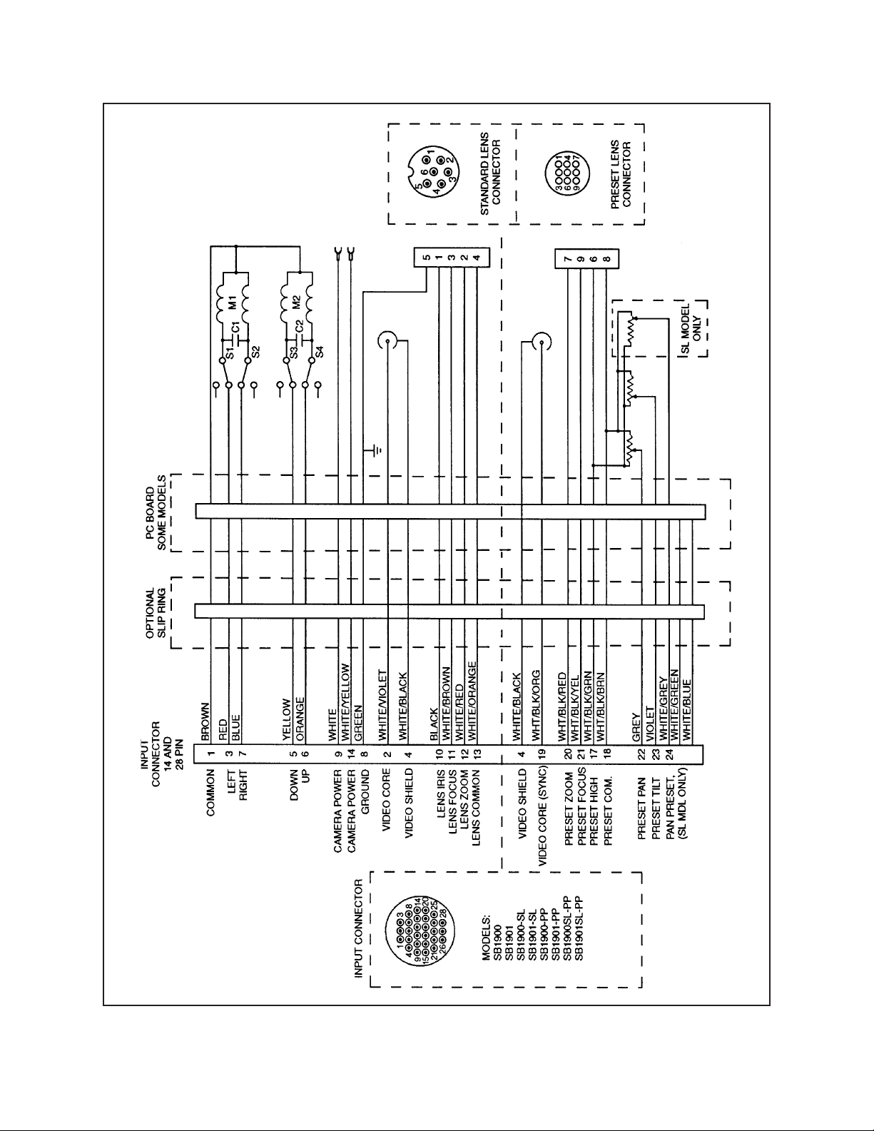
Figure 1. SB1900 Series Wiring Diagram
Pelco Manual C467M-D (5/95) 3
Page 6
4.3 MOUNTING INSTRUCTIONS
Determine the type of mounting desired. The enclosure can be mounted in a hard ceiling, completely replace a standard 2' x 2' suspended ceiling tile using the
APSB19 optional faceplate, or be inserted through a
cut-out in a standard 2' x 2' suspended ceiling tile.
Handle the lower dome with care so as not to scratch or
get fingerprints on the viewing window.
4.3.1 Suspended Ceiling Mounting
4.3.1.1 Suspended Ceiling -
Preferred Method
1. Determine the location for mounting the enclosure
and remove the appropriate ceiling tile.
IMPORTANT: When installing the enclosure in a 2' x 4' ceiling grid, cut the ceiling tile
in half and install an additional “T” rail for
support.
2. Remove the factory assembled 12.5" round faceplate from the back box by disengaging the serrated studs.
3. Remove the factory assembled 14.5" square mounting plate by removing the four (4) 1/4-20 bolts.
4. Place the 14.5" square mounting plate on the removed ceiling tile, centering all four edges of the
plate to the tile. Draw an outline of the octagon
opening in the sub-plate onto the tile.
5. Using a sharp knife or keysaw, cut out the octagon
outlined on the tile.
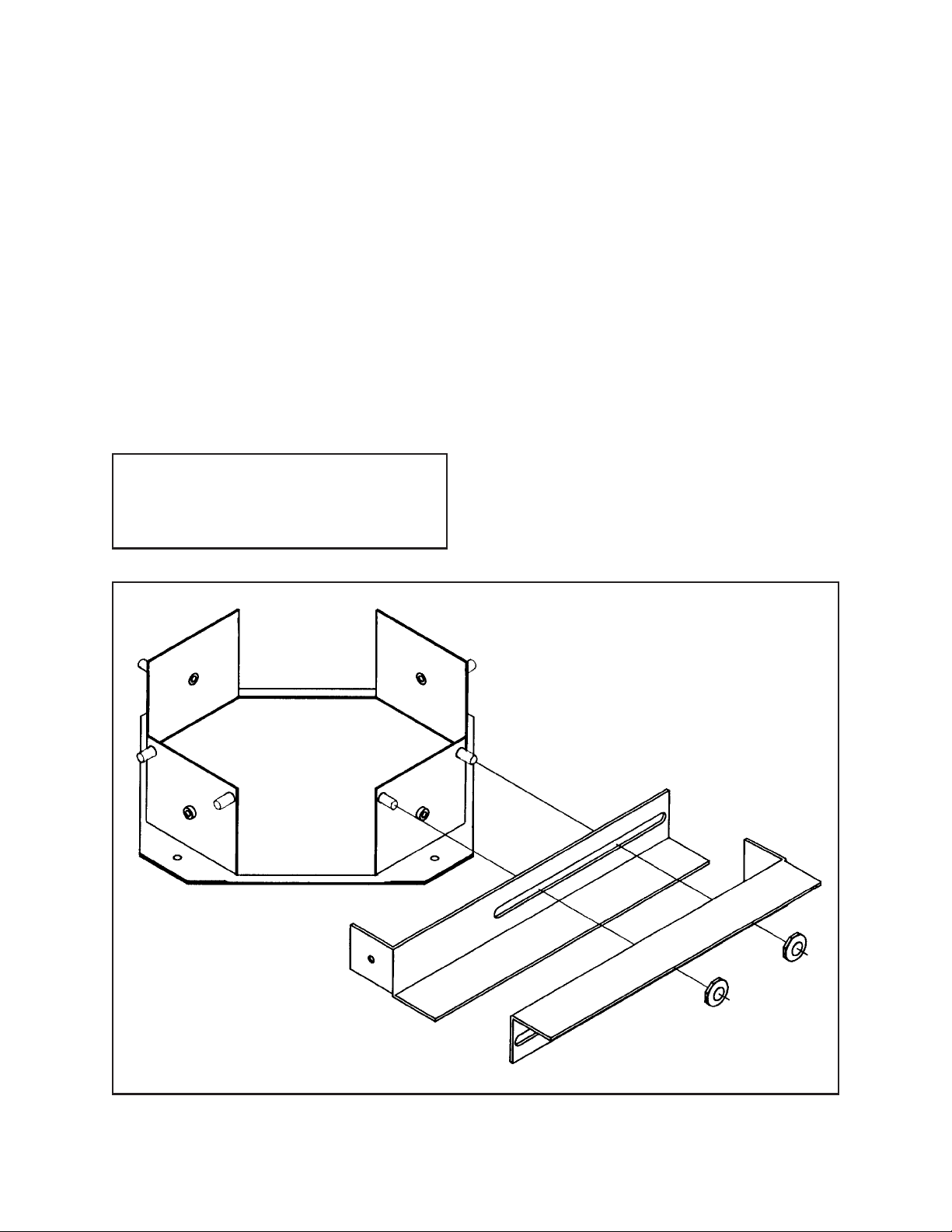
6. Replace the ceiling tile and place the mounting
plate on top of it, centering the plate on the tile.
Attach the back box mount rails with 1/4-20 nuts
(provided) to two opposite sides of the mounting
plate. Use these mount rails to secure the back box
in place so that it can’t move when inserting or
removing the dome drive unit, and so that all of
the weight of the unit is not on the ceiling tile, per
local code. (Refer to Figure 2.)
Figure 2. Back Box Mounting Rail Installation
4 Pelco Manual C467M-D (5/95)
Page 7

7. Slide the back box through the ceiling tile and
mounting plate and replace the four (4) 1/4-20 bolts
and tighten to secure the back box to the mounting
plate.
8. Check the alignment of the back box to the ceiling
tile by attaching the 12.5" round faceplate trim to
the bottom of the back box, aligning the two studs
with two of the holes in the flanges of the back
box and engaging the studs. The studs should engage, while leaving a very minimal gap between
the ceiling and faceplate trim. Loosen the 1/4-20
hardware in the sides of the back box and make
adjustments as required. Insure that the face of the
back box is level with the ceiling.
9. Attach the lens and camera head to the tilt table
(hardware not supplied), if not factory pre-assembled,
using the camera/lens position template supplied
as a guide (see Figure 3). Locate the lens and camera so that when the notched area in the template
is fitted under the tilt table, the lens and camera do
not project further out from the tilt table than allowed by the template. Also, the lens must not
project higher than the long end of the template.
NOTE: If the camera and lens do not fit within
the boundaries of the template, they will not fit
inside the dome and need to be replaced with
smaller units.
10. Mount the camera power supply onto the bracket
provided, if not factory pre-assembled. (Screws to
mount the camera power supply and lens are not
provided with the pan/tilt.)
NOTE: For PC1804B and PC900U cameras,
remove the mounting bracket with the two 1/420 holes in it from the camera’s power supply,
align the camera power supply so that the two
(2) threaded holes in the power supply align
over two of the round holes in the camera power
supply bracket on the pan/tilt, and attach it with
the screws provided with the camera.
11. Hook up camera power, video, and lens with the
connectors supplied, if not factory pre-assembled.
Coil the excess camera cable and tie it down with
tie-wraps to the pan/tilt body.
NOTE: To insert or remove the drive unit from
the back box, the drive unit may need to be rotated 90° so that the wiring cover and/or camera power supply does not interfere with the
side of the back box. If difficulty inserting or
removing the drive unit is experienced, slowly
and gently rotate the drive unit 90°.
12. Engage the connector of the coil cord into the connector of the pan/tilt and attach the safety clamp;
then insert the pan/tilt into the back box, feeding
the coil cord back through the opening in the top
of the back box. Position the pan/tilt in the back
box so that the horizontal studs in the pan/tilt mount
bracket align with the slots in the back box mount
bracket. Lift the pan/tilt until it reaches its stop,
then slide it to one side while letting it drop about
1/4 inch (see Figure 4).
LENS
3.25
(8.26)
MAX
TILT TABLE
.875
(2.22)
MAX
GENERAL LENS MAXIMUM EXTENSIONS
PAST EDGES OF TILT TABLE
NOTE: VALUES IN PARENTHESE ARE CENTIMETERS;
ALL OTHERS ARE IN INCHES
6.5
(16.51)
MAX
CAMERA
1.625
(4.13)
MAX
SUPPLIED
TEMPLATE
Figure 3. Camera/Lens Mounting Dimensions
Pelco Manual C467M-D (5/95) 5
Page 8

13. Attach the dome to the pan/tilt by aligning the two
ball studs protruding through the flange of the dome
with the two holes in the dome attachment brackets and engaging the studs.
14. Attach the safety chain on the side of the back box
to the short 4-40 threaded screw in the 12.5" round
faceplate trim with the provided hardware.
15. Attach the faceplate trim to the back box by aligning the two serrated studs with two of the holes in
the edges of the back box and engaging the studs.
16. Operate the pan/tilt to verify that there are no obstructions or dragging cables within the back box
or dome.
UPPER MOUNTING PLATE
INSIDE BACK COVER
SAFETY SPRING CLIP
ATTACHED TO COIL CORD
(CAN BE POSITIONED
180° FROM SHOWN)
LOWER MOUNTING PLATE
ATTACHED TO PAN AND TILT
Figure 4. Pan/Tilt Mounting Detail
6 Pelco Manual C467M-D (5/95)
Page 9

4.3.1.2 Suspended Ceiling Tile
Replacement Mounting
template. Also, the lens must not project higher than
the long end of the template.
To mount the enclosure into a suspended ceiling grid
where the tile is replaced, perform the following steps.
1. Determine the location for mounting the enclosure
and remove the appropriate ceiling tile.
IMPORTANT: When installing the enclosure in a 2' x 4' ceiling grid, cut the ceiling tile
in half and install an additional “T” rail for
support.
2. Angle the 23.75" back box mounting plate (part
number APSB19, which must be ordered separately) through the grid opening and set the plate
into the grid. Attach the back box mount rails with
1/4-20 nuts (provided) to two opposite sides of the
mounting plate (see Figure 2). Use these mount
rails to secure the back box in place so that it can’t
move when inserting or removing the dome drive
unit, and so that all of the weight of the unit is not
on the ceiling tile, per local code.
3. Remove the factory assembled 12.5" round face-
plate from the back box by disengaging the serrated studs.
4. Remove the factory assembled 14.5" square mount-
ing plate by removing the four (4) 1-4/20 bolts.
5. Slide the back box through the mounting plate and
replace the four (4) 1/4-20 bolts and tighten to secure the back box to the mounting plate.
NOTE: If the camera and lens do not fit within
the boundaries of the template, they will not fit
inside the dome and need to be replaced with
smaller units.
8. Mount the camera power supply onto the bracket
provided, if not factory pre-assembled. (Screws to
mount the camera power supply and lens are not
provided with the pan/tilt.)
NOTE: For PC1804B and PC900U cameras,
remove the mounting bracket with the two 1/420 threaded holes in it from the camera’s power
supply, align the camera power supply so that
the two (2) threaded holes in the power supply align over two of the round holes in the
camera power supply bracket on the pan/tilt,
and attach it with the screws provided with
the camera.
9. Hook up camera power, video, and lens with the
connectors supplied, if not factory pre-assembled.
Coil the excess camera cable and tie it down with
tie-wraps to the pan/tilt body.
NOTE: To insert or remove the drive unit from
the back box, the drive unit may need to be rotated 90° so that the wiring cover and/or camera power supply does not interfere with the
side of the back box. If difficulty inserting or
removing the drive unit is experienced, slowly
and gently rotate the drive unit 90°.
6. Check the alignment of the back box to the mounting plate by attaching the 12.5" round faceplate
trim to the bottom of the back box, aligning the
two studs with two of the holes in the flanges of
the back box and engaging the studs. The studs
should engage, while leaving a very minimal gap
between the ceiling and faceplate trim. Loosen the
1/4-20 hardware in the sides of the back box and
make adjustments as required. Insure that the face
of the back box is level with the ceiling.
7. Attach the lens and camera head to the tilt table (hardware not supplied), if not factory pre-assembled, using the camera/lens position template supplied as a
guide (see Figure 3). Locate the lens and camera so
that when the notched area in the template is fitted
under the tilt table, the lens and camera do not project
further out from the tilt table than allowed by the
Pelco Manual C467M-D (5/95) 7
10. Engage the connector of the coil cord into the connector of the pan/tilt and attach the safety clamp;
then insert the pan/tilt into the back box, feeding
the coil cord back through the opening in the top
of the back box. Position the pan/tilt in the back
box so that the horizontal studs in the pan/tilt mount
bracket align with slots in the back box mount
bracket. Lift the pan/tilt until it reaches its stop,
then slide it to one side while letting it drop about
1/4 inch (see Figure 4).
11. Attach the dome to the pan/tilt by aligning the two
ball studs protruding through the flange of the dome
with the two holes in the dome attachment brackets and engaging the studs.
Page 10

12. Attach the safety chain on the side of the back box
to the short 4-40 threaded screw in the 12.5" round
faceplate trim with the provided hardware.
13. Attach the faceplate trim to the back box by aligning the two serrated studs with two of the holes in
the edges of the back box and engaging the studs.
14. Operate the pan/tilt to verify that there are no obstructions or dragging cables within the back box
or dome.
4.3.2 Hard Ceiling Mounting
To mount the enclosure into a hard ceiling, perform the
following steps.
1. Determine the location and direction of the enclosure. Ideally, the enclosure cutout should be parallel and adjacent, or perpendicular, to any ceiling
structure. Cut an opening (refer to Figure 8 for dimensions).
2. Remove the factory assembled 12.5" round faceplate from the back box by disengaging the serrated studs.
3. Remove the factory assembled 14.5" square mounting plate by removing the four (4) 1/4-20 bolts and
place it over the opening. Attach the back box
mount rails to the mounting plate with 1/4-20 nuts
(provided) to two opposite sides of the mounting
plate (see Figure 2). Use these mount rails to secure the back box in place so that it can’t move
when inserting or removing the dome drive unit,
and so that all of the weight of the unit is not on
the ceiling tile, per local code.
4. Slide the back box through the mounting plate and
replace the four (4) 1/4-20 bolts and tighten to secure the back box to the mounting plate.
5. Check the alignment of the back box to the ceiling
by attaching the 12.5" round faceplate trim to the
bottom of the back box, aligning the two studs with
two of the holes in the flanges of the back box and
engaging the studs. The studs should engage, while
leaving a very minimal gap between the ceiling
and faceplate trim. Loosen the 1/4-20 hardware in
the sides of the back box and make adjustments
are required. Insure that the face of the back box is
level with the ceiling.
6. Attach the lens and camera head to the tilt table
(hardware not supplied), if not factory pre-assembled,
using the camera/lens position template supplied
as a guide (see Figure 3). Locate the lens and camera so that when the notched area in the template
is fitted under the tilt table, the lens and camera do
not project further out from the tilt table than allowed by the template. Also, the lens must not
project higher than the long end of the template.
NOTE: If the camera and lens do not fit within
the boundaries of the template, they will not fit
inside the dome and need to be replaced with
smaller units.
7. Mount the camera power supply onto the bracket
provided, if not factory pre-assembled. (Screws to
mount the camera power supply and lens are not
provided with the pan/tilt.)
8. Hook up camera power, video, and lens with the
connectors supplied, if not factory pre-assembled.
Coil the excess camera cable and tie it down with
tie-wraps to the pan/tilt body.
NOTE: To insert or remove the drive unit from
the back box, the drive unit may need to be rotated 90° so that the wiring cover and/or camera power supply does not interfere with the
side of the back box. If difficulty inserting or
removing the drive unit is experienced, slowly
and gently rotate the drive unit 90°.
9. Engage the connector of the coil cord into the connector of the pan/tilt and attach the safety clamp;
then insert the pan/tilt into the back box, feeding
the coil cord back through the opening in the top
of the back box. Position the pan/tilt in the back
box so that the horizontal studs in the pan/tilt mount
bracket align with slots in the back box mounting
bracket. Lift the pan/tilt until it reaches its stop,
then slide it to one side while letting it drop about
1/4 inch (see Figure 4).
10. Attach the dome to the pan/tilt by aligning the two
ball studs protruding through the flange of the dome
with the two holes in the dome attachment brackets and engaging the studs.
11. Attach the safety chain on the side of the back box
to the short 4-40 threaded screw in the 12.5" round
faceplate trim with the provided hardware.
8 Pelco Manual C467M-D (5/95)
Page 11

12. Attach the faceplate trim to the back box by aligning the two serrated studs with two of the holes in
the edges of the back box and engaging the studs.
13. Operate the pan/tilt to verify that there are no obstructions or dragging cables within the back box
or dome.
2. Pan to the desired left position, remove the drive
unit from the back box and adjust the pan limit
stop until the actuator clicks, and lock into position. Replace the drive unit.
3. Pan to the right and left to verify the exact positioning.
4.4 CONNECTOR ASSEMBLY
To install and test the SB1900 Series enclosures you
may need to fabricate the interconnecting cable as outlined below. (Pretested wire harnesses, WH1900-06 and
WH1900-25, are optional cables for the SB1900 Series dome enclosures).
1. Strip back the cable jacket approximately 2 inches
and separate the individual conductors.
2. Attach spade lugs to each wire and mate BNC to
coax and camera sync.
3. Pop out a knock-out in one of the ends of the J-box
(on top of back box). Thread cable into J-box
through knock-out and attach each wire to the terminal block, as marked beside terminal block, and
engage BNC connectors or video and camer sync.
4.5 ADJUSTMENTS
To adjust the pan/tilt limits, perform the following steps.
Refer to Figure 5 for limit stop locations.
CAUTION: Do not attempt to adjust limit
stops when the pan/tilt is in operation. Damage
to the equipment can result. Also, do not operate equipment without limit stops. Note that SL
models are supplied without pan limit stops,
therefore, no adjustments are necessary.
4. The tilt limit is factory set at 0 to -90° travel (hori-
zontal to vertical). The tilt can be adjusted to any
point between horizontal and vertical; however,
under normal conditions the tilt limits should not
require adjustment.
5. To alter the factory set tilt limit*, bend the actuator stops on the microswitches (see Figure 6).
Move the tilt table to the desired position and adjust the actuators until the switch clicks; lock into
position.
6. Tilt up and down to verify exact positioning.
* It should be emphasized that only very minor adjustments should be made by bending the actuator attached
to the microswitch; and then, only for the reason of
bringing it within factory specifications.
LIMIT STOP LEFT
LIMIT STOP RIGHT
LIMIT STOP FIXED
LIMIT ACTUATOR
Factory pan limits are set to 0-355° and tilt limits are to
0-90° (horizontal to vertical). Under normal conditions,
the tilt limits should not have to be reset.
To adjust limit stops, perform the following steps:
1. Pan to the right using the joystick control until the
desired pan limit is reached. Remove the drive unit
from the back box and adjust the pan limit stop
until the actuator clicks. Lock the limit into position. Replace the drive unit.
NOTE: FIGURE IS A REPRESENTATION OF AN ACTUAL UNIT
WITH SOME PARTS NOT SHOWN TO PROVIDE
CLARITY OF LIMIT STOP LOCATIONS
Figure 5. Limit Stop Locations
Pelco Manual C467M-D (5/95) 9
Page 12

5.0 CARE AND MAINTENANCE
Regularly scheduled maintenance will prolong the operational life and appearance of the equipment.
If dust or other debris accumulates on the inside of the
lower dome, remove with clean air pressure only. Compressed air cans are available from commercial photographic equipment and supply dealers.
IMPORTANT: The lower dome of the enclosure is an optical surface. When cleaning the
inner surface of the dome and viewing window,
treat as carefully as you would a fine camera
lens. Do not use water, liquid or spray cleaners
of any kind on coated inner surface of dome.
Clean the outer surface of the dome and the inner surface of the viewing window with a non-abrasive cleaning cloth and anti-static cleaner that is safe for use on
acrylic plastic. Do not use kerosene or similar substances that can scratch the surface.
LOCKING SCREW
FRONT
LIMIT ACTUATOR
DOWN UP
UP
DOWN
Figure 6. Tilt Limit Stop Modification
10 Pelco Manual C467M-D (5/95)
Page 13

6.0 EXPLODED ASSEMBLY DIAGRAM
Refer to Figure 7 for an exploded assembly diagram of the SB19 enclosure.
PP ONLY
*
NON SL ONLY
**
EXPASB1900
EXPASB1900PP
Figure 7. SB19 Exploded Assembly Diagram
Pelco Manual C467M-D (5/95) 11
Page 14

7.0 EXPLODED ASSEMBLY MECHANICAL PARTS LIST
Item Qty Description Pelco Part Number
1 1 UL, Pad, camera, black .062" thick EH200010004
2 1 PCB assembly, pan/tilt PCB3000100ASSY
3 1 Bushing, 3/8" tilt shaft PT180010001
4 1 Shaft, tilt table PT18004002COMP
5 1 Sprocket .25" bore with pin and SS PT18004003COMP
6 2 Ball stud receiver PT180410001
7 Not used
8 1 Tilt Chain assembly PT18041006ASSY
9 1 Pan Chain assembly PT18041007ASSY
10 1 Tilt shaft, motor side PT18041011WA
11 1 Frame body, weld assembly PT18041012WA
12 2 Dome attachment bracket PT18044002COMP
13 1 Spindle, pan PT18044055COMP
14 1 Mount, lower pan and tilt PT18044006COMP
15 1 Bracket, PC1804-B power supply PT18044009COMP
16 1 Pan motor heat sink mount PT1804410COMP
17 1 Pan motor heat sink PT18044011COMP
18 1 Connector spacer, spindle mount PT18044014COMP
19 1 Bushing PT250010004
20 1 Bushing, 1/4", tilt shaft PT250010005
21 1 Sprocket, pan spindle PT25004104COMP
22 1 Tilt table PT25004106COMP
23 1 Tilt limit actuator PT25004108COMP
24 1 Collar, tilt table switch shaft PT25004121COMP
25 1 Spricket, 1/4" with SS and pilot PT25004125COMP
26 1 Bearing, flange PT350010000
27 2 UL, motor, 4 rpm, 24VAC PT350010010
28 1 Plate, bearing PT35001060COMP
29 1 Collar, tilt table motor side PT89104001COMP
30 4 NP spacer, 1/4" OD x .125, #6 clear SPA8500
31 2 Switch SWI1SM1
32 2 Switch actuator with insulator SWIJS138B
33 6 NP cable, S/S x inch E70810001
34 2 Connector ring, 14-wire #4 stud E70810002
35 1 Coil cord PT180410002
36 1 Black box assembly, 10.9" octagon SB10841010ASSY
37 1 Trim ring assembly SB18044100COMP
38 1 Mount, upper pan/tilt SB18044105COMP
39 2 J-box end SB18044105COMP
40 1 J-box cover SB18044006COMP
41 1 Boack box mount plate SSB18044007COMP
42 2 BNC panel mount bracket SB18044009COMP
43 1 8" dome camera/lens position template SB184220COMP
44 Not used
45 4 Back box mount rail SB194002COMP
46 2 Terminal block, 10-position PC mount TRB-2MV-10
47 1 Black opaque dome with smoked viewing window SB194200COMP
and mounting studs
1 Black opaque dome with clear viewing window SB194300COMP
and mounting studs
12 Pelco Manual C467M-D (5/95)
Page 15

7.0 EXPLODED ASSEMBLY MECHANICAL PARTS LIST (continued)
Item Qty Description Pelco Part Number
48 Not used
49 Not used
50 Not used
51 1 Slip ring, 24 circuit for presets 250010000
52 Not used
53 Not used
54 Not used
55 1 Bracket, tilt pot PT18044012COMP
56 1 Bracket, LPP lens connector PT18044013COMP
57 1 Gear, 1.875 plastic PT250010002
58 2 Gear, 1.5 plastic PT250010006
59 2 Pot, precision 10K POTP010.0K
60 1 Gear, spindle feedback, non-SL PT25004114COMP
61 1 Pan feedback pot PT25004116COMP
62 thru 70 Not used
71 2 Ring snap 15510000
72 1 Bracket, pan limit 2704051COMP
73 3 Limit stop, pan univ 5804006COMP
74 Not used
75 1 Grommet, neoprene GRO2172N
76 Not used
77 Not used
78 1 Pan limit stop ring PT18044018COMP
79 1 Bracket, pan limit mount PT18044019COMP
80 1 Pan limit actuator pin PT18044020COMP
Pelco Manual C467M-D (5/95) 13
Page 16

8.0 MODELS
DD1900 Dome drive unit for SB1900. (UL)
SB1900-PP Same as the SB1900, except this
package features the factory installed
preset (PP) option.
DD1900-PP Dome drive unit for SB1900-PP.
DD1900-SL Dome drive unit for SB1900-SL.
(UL)
DD1900SL-PP Dome drive unit for SB1900SL-PP.
SB19 Drop ceiling discreet surveillance
enclosure with black opaque lower
dome with less than 1 f-stop light attenuation and all aluminum back box
which mounts above the ceiling.
(Camera mount supplied.) (UL)
SB19-1 Same as SB19 except supplied with
clear viewing slot in the dome for
virtually zero light loss. (UL)
SB1900 This system package includes the
SB19 black opaque dome enclosure
plus a 24 VAC pan/tilt factory assembled inside the back box. It provides factory pre-wired feedthrough
for all control functions (i.e., pan/tilt,
motorized zoom lens, camera power
(24 VAC) and video). All connections
are made at the terminal blocks on
top of the back box, eliminating wiring harnesses made in the field. This
feature significantly reduces installation time while increasing the reliability and serviceability of the system.
(UL)
SB1901 Same as SB1900 except supplied
with clear viewing slot in the dome
for virtually zero light loss. (UL)
SB1900-SL Same as the SB1900, except this
package features 360° continuous
pan rotation. (UL)
SB1901-SL Same as SB1900-SL except supplied
with clear viewing slot in the dome
for virtually zero light loss. (UL)
SB1901-PP Same as SB1900-PP except supplied
with clear viewing slot in the dome
for virtually zero light loss.
SB1900SL-PP Same as the SB1900-SL with the
addition of the preset (PP) option.
SB1901SL-PP Same as SB1900SL-PP except sup-
plied with clear viewing slot in the
dome for virtually zero light loss.
9.0 RECOMMENDED CONTROLS
The following controls are recommended for use with
the SB1900 Series enclosures.
9.1 MODELS SB1900 AND SB1900-SL
Hardwire Short-Distance Controls
for 24 VAC Operation
MPT24DT Desk top joystick control module for
24 VAC pan/tilts.
MPTA24DT Same as MPT24DT except with auto/
random scan operation.
MLZ6DT Desk top zoom lens control module
with auto/manual iris control.
MEH24DT Desk top enclosure control module
for 24 VAC camera on/off.
Coaxitron System 2000
MPT9000CZ Desk top Coaxitron transmitter/control
with pan/tilt joystick, zoom lens, and
four accessory function controls.
CX9024RXI Desk top Coaxitron receiver for 24
VAC pan/tilts, zoom lens, 24 VAC
camera power and optional four accessory functions. Indoor use.
A9000 Auto/random scan plug-in module
for all Coaxitron receivers.
CX900TLC System test and receiver manual con-
trol board for Coaxitron receivers
(plug-in module).
14 Pelco Manual C467M-D (5/95)
Page 17

9.2 MODELS SB1900, SB1900-SL,
SB1900-PP AND SB1900SL-PP
IOP19B1C B/W NTSC 6X camera and lens pkg.
with preset positioning.
CM7500 Series Coaxitron Matrix Switcher/Control
System rack mount card cage with
CPU and power supply. Capable of
up to 64 inputs and up to 4 monitor
outputs. (See C584 product specification sheet for details).
CM8500 Series Matrix Switcher/Control System ca-
pable of up to 32 inputs and 16
monitor outputs. (See C501 product
specification sheet for details).
CM9500 Series Coaxitron Matrix Switcher/Control
System rack mount card cage with
CPU and power supply. Capable of
up to 96 inputs and 16 monitor outputs. (See C500 product specification
sheet for details).
CX9024RXI-PP Coaxitron indoor receiver for 24 VAC
pan/tilts, zoom lens, 24 VAC camera
power and optional four accessory
functions, with preset option (PP) for
pan/tilt and lenses (use with models
SB1900-PP and SB1900SL-PP).
(Must be used with CM7500/CM9500
series controls only.)
CX900TLC System test and receiver manual con-
trol board for Coaxitron receivers
(plug-in module).
MPT9500 Desktop controller (coaxitron com-
patible) with full PTZ, joy stick, 8
auxiliary functions.
10.0 OPTIONS
RB24 Relay box for 24 VAC pan/tilts and
scanners. Extends operating distance
(control to relay box) up to a maximum of 14,500 feet utilizing 16 Awg.
APSB19 23.75" square faceplate for suspended
ceiling applications.
APSB19-1 Same as APSB19 except black finish.
IOP19B1B B/W NTSC 6X camera and lens pkg.
IOP19B1G B/W NTSC 10X camera/lens pkg.
IOP19C1B Color NTSC 6X camera and lens pkg.
IOP19C1C Color NTSC 6X camera and lens
pkg. with preset positioning.
IOP19C1G Color NTSC 10X camera and lens pkg.
WH1900-06 6 foot wire harness with bare wire on
one end (for connection to the terminal blocks in the junction box on top
of the back box) and a 37 position connector on the other end (for connection to Coaxitron receiver).
WH1900-25 Same as WH1900-06, except 25 feet
long.
11.0 SPECIFICATIONS
MECHANICAL
Construction:
Pan/tilt Aluminum
Back box Aluminum
Lower dome Acrylic hemisphere with a clear,
distortion-free viewing window
with no light attenuation factor
(SB1901 Series) or smoked, distortionfree viewing window with less than
1 f-stop light attenuation (SB1900 Series); rotates with the pan/tilt/camera/
lens
Maximum
Camera/Lens
Size: 6.5" L x 4.5" W x 3.25" H, including
BNC (16.51 cm x 11.43 cm x 8.25 cm);
maximum camera head width is
2.50" (6.35 cm) (see Figure 3)
Max. Camera
Power Supply
Size: 2.5" x 5.0" x 2.5"
(6.35 cm x 12.7 cm x 6.35 cm)
Pan: 0-355° movement in horizontal
plane (Models SB1900, SB1900-PP)
360° continuous rotation (Models
SB1900-SL, SB1900SL-PP)
Pelco Manual C467M-D (5/95) 15
Page 18

Pan Speed: 24°/sec ± 1°
Tilt: -90° movement from horizontal plane
Tilt Speed: 12°/sec ± .5°
Maximum Load: 10 lbs (4.6 kg)
Lens Connector: Hirchmann 6100 type (mate supplied)
for non-PP models
AMP CPC type (mate supplied) for
PP models
Motors: Synchronous type, continuous duty,
instantaneous reversing
Gearing: Chain drive
Bearings:
Pan Heavy duty ball bearing and Oilite
bronze bushing
Tilt Oilite bronze bushing
Braking: Friction
ELECTRICAL
Input Voltage: 24 VAC required for pan/tilt
Power
Requirements:
Pan .31 amp (7.5 vA)
Tilt .31 amp (7.5 vA)
Connectors: Terminal strips inside J-box on the top of
the back box (all functions except video:
camera power, lens, pan/tilt and presets).
Video
Connector: BNC
Camera Power: Spade lugs, 24 VAC
Limit Switches:
Pan 5 amp, 10 million cycle rating (ex-
ternal adjustment) on non-SL
Tilt 5 amp, 10 million cycle rating (factory
set)
Conductor
Requirements:
Non-PP
models Pan/tilt (5 plus ground), Lens (4),
Camera AC (2), Video (coax), Camera Sync (coax)
PP models Pan/tilt (9 plus ground), Lens (6),
Camera AC (2), Video (coax), Camera Sync (coax)
GENERAL
Environment: Indoor
Temperature
Range: 14°F to 122°F (-10°C to +50°C)
Dimensions: See Figure 8
9.25
1.65
(4.19)
11.00
(27.94)
NOTE: VALUES IN PARENTHESES ARE CENTIMETERS; ALL OTHERS ARE INCHES.
(23.50)
3.10
(7.87)
8.50
(21.59)
12.50
(31.75)
A
B
C
WHERE:
A 10.90 (27.69)
B 7.70 (19.56)
C 3.20 (8.13)
1.80
(4.58)
7.93
(20.14)
C
B
A
Figure 8. SB19 Dimension Drawing
16 Pelco Manual C467M-D (5/95)
Page 19

12.0 WARRANTY AND RETURN
INFORMATION
WARRANTY
Pelco will repair or replace, without charge, any merchandise proved
defective in material or workmanship for a period of one year after the date
of shipment.
Exceptions to this warranty are as noted below:
• Five years on FT/FR8000 Series fiber optic products.
• Three years on Genex
keyboard).
• Three years on Camclosure
CC3701H-2, CC3701H-2X, CC3751H-2, CC3651H-2X, MC3651H-2,
and MC3651H-2X camera models, which have a five-year warranty.
• Two years on standard motorized or fixed focal length lenses.
• Two years on Legacy®, CM6700/CM6800/CM9700 Series matrix, and
DF5/DF8 Series fixed dome products.
• Two years on Spectra
ing when used in continuous motion applications.
• Two years on Esprit
wiper blades).
• Eighteen months on DX Series digital video recorders, NVR300
Series network video recorders, and Endura
network-based video products.
• One year (except video heads) on video cassette recorders (VCRs).
Video heads will be covered for a period of six months.
• Six months on all pan and tilts, scanners or preset lenses used in
continuous motion applications (that is, preset scan, tour and auto scan
modes).
Pelco will warrant all replacement parts and repairs for 90 days from the
date of Pelco shipment. All goods requiring warranty repair shall be sent
freight prepaid to Pelco, Clovis, California. Repairs made necessary by
reason of misuse, alteration, normal wear, or accident are not covered
under this warranty.
Pelco assumes no risk and shall be subject to no liability for damages or
loss resulting from the specific use or application made of the Products.
Pelco’s liability for any claim, whether based on breach of contract,
negligence, infringement of any rights of any party or product liability,
relating to the Products shall not exceed the price paid by the Dealer to
Pelco for such Products. In no event will Pelco be liable for any special,
incidental or consequential damages (including loss of use, loss of profit
and claims of third parties) however caused, whether by the negligence
of Pelco or otherwise.
The above warranty provides the Dealer with specific legal rights. The
Dealer may also have additional rights, which are subject to variation from
state to state.
If a warranty repair is required, the Dealer must contact Pelco at (800)
289-9100 or (559) 292-1981 to obtain a Repair Authorization number
(RA), and provide the following information:
1. Model and serial number
2. Date of shipment, P.O. number, Sales Order number, or Pelco invoice
number
3. Details of the defect or problem If there is a dispute regarding the
warranty of a product which does not fall under the warranty conditions
stated above, please include a written explanation with the product
when returned.
Method of return shipment shall be the same or equal to the method by
which the item was received by Pelco.
®
Series products (multiplexers, server, and
®
and fixed camera models, except the
®
, Esprit®, ExSite™, and PS20 scanners, includ-
®
and WW5700 Series window wiper (excluding
™
Series distributed
RETURNS
In order to expedite parts returned to the factory for repair or credit, please
call the factory at (800) 289-9100 or (559) 292-1981 to obtain an
authorization number (CA number if returned for credit, and RA number
if returned for repair).
All merchandise returned for credit may be subject to a 20% restocking
and refurbishing charge.
Goods returned for repair or credit should be clearly identified with the
assigned CA or RA number and freight should be prepaid. Ship to the
appropriate address below.
If you are located within the continental U.S., Alaska, Hawaii or Puerto
Rico, send goods to:
Service Department
Pelco
3500 Pelco Way
Clovis, CA 93612-5699
If you are located outside the continental U.S., Alaska, Hawaii or Puerto
Rico and are instructed to return goods to the USA, you may do one of the
following:
If the goods are to be sent by a COURIER SERVICE, send the goods to:
Pelco
3500 Pelco Way
Clovis, CA 93612-5699 USA
If the goods are to be sent by a FREIGHT FORWARDER, send the goods
to:
Pelco c/o Expeditors
473 Eccles Avenue
South San Francisco, CA 94080 USA
Phone: 650-737-1700
Fax: 650-737-0933
This equipment contains electrical or electronic components that must be recycled properly to comply with Directive 2002/96/EC of the European Union
regarding the disposal of waste electrical and electronic equipment (WEEE). Contact your local dealer for procedures for recycling this equipment.
Pelco Manual C467M-D (5/95) 17
Page 20

Pelco
3500 Pelco Way • Clovis, CA 93612-5699
(559) 292-1981 • (800) 289-9100
FAX (800) 289-9150 or (559) 292-3827
International customers call 1-559-292-1981 or FAX 1-559-348-1120
(Product specifications subject to change without notice.)
18 Pelco Manual C467M-D (5/95)
 Loading...