

Pelco Sarix IBP3-PLMT Pole Mount Adapter installation manual
SARIX® IBP3-PLMT POLE MOUNT ADAPTER
Important Safety Instructions
1. Read these instructions.
2. Keep these instructions.
3. Follow these instructions.
4. Installation should be done by qualified personnel and conform to all local codes.
5. Use only installation methods and materials capable of supporting four times the maximum specified load.
6. Use stainless steel
Description
The IBP3-PLMT pole mount adapter is engineered for use with all Sarix® IBP Series Environmental Bullet Cameras. It can be installed on a horizontal/vertical
pipe or pole that has a diameter of 7.62 cm (3 in.) to 20.32 cm (8 in.).
Parts List
The following parts are supplied.
Qty Description
1 IBP3-PLMT pole mount adapter
2 Stainless steel straps
4 Torx
6 Torx M4 x 14 mm, T20 tamperproof screws
5 Torx 8-32 x 0.75, T20 screws
The following parts are required but not supplied.
Qty Description
1 Sarix IBP Series Environmental Bullet Camera
1 Torx T20 bit driver, tamperproof
1 Surface mount back box with adapter plate, Part no. IBP3BBAP-ES
hardware to fasten the mount to outdoor surfaces.
®
8-32 x 0.375, T20 screws
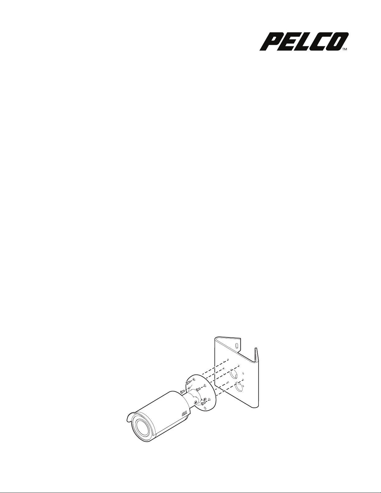
Installing the IBP3-PLMT Indoors Without a Surface Mount Back Box
The IBP Series camera mounts directly on the pole mount adapter using five Torx 8-32 x 0.75, T20 tamperproof screws (supplied). Camera and network cable
connections are managed behind the adapter.
Figure 1. Indoor Installation Without a Surface Mount Back Box
INSTALLATION MANUAL
C2273M | 5/21
www.pelco.com
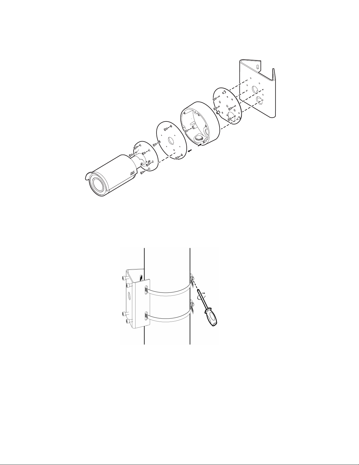
Installing the IBP3-PLMT Indoors/Outdoors With a Surface Mount Back Box
6, 7
8, 9
3, 4
1
2
5
An adapter plate and surface mount back box are installed on the pole mount adapter as shown in Figure 2. The Sarix IBP Series Environmental Bullet
Camera mounts on the back box lid and is attached to the back box. The camera cable connections are made and contained inside the back box.
Figure 2. Indoor/Outdoor Inst
allation with IBP3BBAP-ES Surface Mount Back Box
1. Attach the IBP3BBAP-ES surface mount back box adapter plate to the IBP3-PLMT pole mount adapter using four 8-32 x 0.375 screws (supplied).
2. Place the IBP3BBAP-ES surface mount back box on the adapter plate standoffs, and then secure with the three screws supplied with the back box.
3. Thread the two stainless steel straps (supplied) through the slot
s in the back of the adapter, and then attach this assembly to the pole or pipe.
WARNING: Only mount one camera system per set of stainless steel straps. Installation Torque: 35-45in.lbs.
Figure 3. Attach Assembly to the Pole
4. Route the network cable into the back of the surface mount back box.
5. Align the red dot inside the back box lid with the red dot on the surface mount back box (see arrows in F
be able to orient the top of the camera with the top of the lid.
igure 2). Then mark the top screw of the lid to
6. Feed the camera cable through the center hole in the IBP3BBAP-ES surface mount back box lid.
7. Align the camera top with the top screw of the lid, and then attach the camera to the lid using the six M4 x 14 mm, T20 tamperproof screws (supplied).
8. Connect the camera cable to the networ
9. Align the red dots on the lid and back box, and then attach the surface mount back box lid/camera to the back box using the three captive lid screws.
k cable and arrange the cables inside the back box.
2 C2273M (5/21)
 Loading...