

OPERATIONS MANUAL
Spectra Enhanced 7 Series
OPERATIONS MANUAL
C6653M | 3/20
PTZ Dome Cameras

Table of Contents
Important Notices Statement ................................................................................................ 3
Regulatory Notices ................................................................................................................. 3
Accessing the Device ............................................................................................................. 6
Accessing Camera Settings ..................................................................................................... 6
Device Configuration Sequence ............................................................................................. 6
Live View .............................................................................................................................. 7
Live View Controls .................................................................................................................. 7
System Menu ........................................................................................................................ 9
General Settings ..................................................................................................................... 9
Backup and Restore.............................................................................................................. 10
Firmware .............................................................................................................................. 11
OSDi ...................................................................................................................................... 11
Snapshot Viewer .................................................................................................................. 12
Storage Management ........................................................................................................... 13
Diagnostics ........................................................................................................................... 14
Network & Security Menu .................................................................................................. 15
Network................................................................................................................................ 15
Users & Security ................................................................................................................... 16
TLS ........................................................................................................................................ 18
Traffic Shaping ...................................................................................................................... 18
802.1x Security ..................................................................................................................... 19
SNMP .................................................................................................................................... 19
Firewall ................................................................................................................................. 20
Imaging .............................................................................................................................. 21
General Settings ................................................................................................................... 21
Exposure ............................................................................................................................... 22
Focus .................................................................................................................................... 24
White Balance ...................................................................................................................... 24
Window Blanking ................................................................................................................. 25
PTZ Menu ........................................................................................................................... 26
Positioning ............................................................................................................................ 26
Presets .................................................................................................................................. 27
Preset Tours .......................................................................................................................... 28
Patterns ................................................................................................................................ 28
Scans .................................................................................................................................... 29
C6653M | 3/20 1

PTZ Zones ............................................................................................................................. 31
Pelco Camera Link ................................................................................................................ 31
A/V Streams Menu ............................................................................................................. 33
Video Presets ....................................................................................................................... 33
Video Configuration ............................................................................................................. 33
Audio Configuration ............................................................................................................. 36
RTP Settings .......................................................................................................................... 36
Smart Compression .............................................................................................................. 37
Events ................................................................................................................................ 40
Sources ................................................................................................................................. 40
Handlers ............................................................................................................................... 42
Analytic Configuration.......................................................................................................... 50
Event Stream ........................................................................................................................ 58
Pelco Troubleshooting Contact Information ......................................................................... 59
C6653M | 3/20 2

Important Notices Statement
Regulatory Notices
This device complies with Part 15 of the FCC Rules. Operation is subject to the following two conditions:
(1) this device may not cause harmful interference, and (2) this device must accept any interference
received, including interference that may cause undesired operation.
Radio and Television Interference
This equipment has been tested and found to comply with the limits of a Class A digital device, pursuant
to Part 15 of the FCC rules. These limits are designed to provide reasonable protection against harmful
interference when the equipment is operated in a commercial environment. This equipment generates,
uses, and can radiate radio frequency energy and, if not installed and used in accordance with the
instruction manual, may cause harmful interference to radio communications. Operation of this
equipment in a residential area is likely to cause harmful interference in which case the user will be
required to correct the interference at his own expense.
Changes and modifications not expressly approved by the manufacturer or registrant of this equipment
can void your authority to operate this equipment under Federal Communications Commission’s rules.
CAN ICES-3(A)/NMB-3(A)
Warranty Statement
For information about Pelco’s product warranty and thereto related information, refer to
www.pelco.com/warranty.
Legal Notice
SOME PELCO EQUIPMENT CONTAINS, AND THE SOFTWARE ENABLES, AUDIO/VISUAL AND RECORDING
CAPABILITIES, THE IMPROPER USE OF WHICH MAY SUBJECT YOU TO CIVIL AND CRIMINAL PENALTIES. APPLICABLE
LAWS REGARDING THE USE OF SUCH CAPABILITIES VARY BETWEEN JURISDICTIONS AND MAY REQUIRE, AMONG
OTHER THINGS, EXPRESS WRITTEN CONSENT FROM RECORDED SUBJECTS. YOU ARE SOLELY RESPONSIBLE FOR
INSURING STRICT COMPLIANCE WITH SUCH LAWS AND FOR STRICT ADHERENCE TO ANY/ALL RIGHTS OF PRIVACY
AND PERSONALTY. USE OF THIS EQUIPMENT AND/OR SOFTWARE FOR ILLEGAL SURVEILLANCE OR MONITORING
SHALL BE DEEMED UNAUTHORIZED USE IN VIOLATION OF THE END USER SOFTWARE AGREEMENT AND RESULT IN
THE IMMEDIATE TERMINATION OF YOUR LICENSE RIGHTS THEREUNDER.
Audio Notice
NOTE: Improper use of audio/visual recording equipment may subject you to civil and criminal
penalties. Applicable laws regarding the use of such capabilities vary between jurisdictions and may
require, among other things, express written consent from the recorded subjects. You are solely
C6653M | 3/20 3

responsible for insuring strict compliance with such laws and for strict adherence to any/all rights of
privacy and personalty.
Video Quality Caution
Frame Rate Notice Regarding User Selected Options
Pelco systems are capable of providing high quality video for both live viewing and playback. However,
the systems can be used in lower quality modes, which can degrade picture quality, to allow for a slower
rate of data transfer and to reduce the amount of video data stored. The picture quality can be
degraded by either lowering the resolution, reducing the picture rate, or both. A picture degraded by
having a reduced resolution may result in an image that is less clear or even indiscernible. A picture
degraded by reducing the picture rate has fewer frames per second, which can result in images that
appear to jump or move more quickly than normal during playback. Lower frame rates may result in a
key event not being recorded by the system. Judgment as to the suitability of the products for users'
purposes is solely the users' responsibility. Users shall determine the suitability of the products for their
own intended application, picture rate and picture quality. In the event users intend to use the video for
evidentiary purposes in a judicial proceeding or otherwise, users should consult with their attorney
regarding any particular requirements for such use.
Open Source Software
This product includes certain open source or other software originated from third parties that is subject
to the GNU General Public License (GPL), GNU Library/Lesser General Public License (LGPL) and different
and/or additional copyright licenses, disclaimers, and notices. The exact terms of GPL, LGPL, and some
other licenses are provided to you with this product. Please refer to the exact terms of the GPL and LGPL
at http://www.fsf.org (Free Software Foundation) or http://www.opensource.org (Open Source
Initiative) regarding your rights under said license. You may obtain a complete corresponding machine-
readable copy of the source code of such software under the GPL or LGPL by sending your request to
digitalsupport@pelco.com; the subject line should read Source Code Request. You will then receive an
email with a link for you to download the source code. This offer is valid for a period of three (3) years
from the date of the distribution of this product by Pelco.
CCC Power Cord Statement
Models shipped to China do not include power cords.
NOTE: A CCC approved power cord must be used to power the equipment when used in China.
KCC Certification
If you know the product is being submitted for KCC certification, add one of the following KCC
statements and the respective heading to the Important Notices page of your English document. If the
C6653M | 3/20 4

KCC mark is not required, do not add this information. The statement should follow the French FCC
translation in the Regulatory Notices section. When the document is translated, this text will already be
included and translated per the requirements.
The Korean Class A statement applies to business/commercial product use. This notice indicates that
the equipment has acquired electromagnetic conformity registration, so sellers and users are required
to use caution.
The Korean Class B statement applies to residential product use. This notice indicates that the
equipment has acquired electromagnetic conformity registration, so it can be used in both residential
and other areas.
Korean Class A EMC
Korean Class B EMC
2.4 GHZ Radio Device
ESD Warning
WARNING: This product is sensitive to Electrostatic Discharge (ESD). To avoid ESD
damage to this product, use ESD safe practices during installation. Before touching,
adjusting or handling this product, correctly attach an ESD wrist strap to your wrist
and appropriately discharge your body and tools. For more information about ESD
control and safe handling practices of electronics, please refer to ANSI/ESD S20.201999 or contact the Electrostatic Discharge Association (www.esda.org).
C6653M | 3/20 5

Accessing the Device
By default, users do not have to log in to view video. If you want to prevent users from viewing
video without logging in, you must change the permissions for public users.
The recommended browsers for your device are Mozilla® Firefox®, Google Chrome, or Microsoft
Edge for Microsoft® Windows® operating systems and Firefox for Mac® operating systems.
Open a web browser.
NOTE: When opening the browser, you may see “This Camera is Not Secure” message. If you know
the user information, then create a user to secure your camera. Otherwise, you can click No
Thanks and establish user accounts at a later date.
Type the camera’s IP address or host name in your browser’s address bar and then click Enter.
NOTE: You can obtain your camera’s IP address or access the camera using VXToolbox software.
Click Log In (if a user name and password exist, a log in dialog box appears).
Accessing Camera Settings
Access to camera settings is determined by user permissions. If you do not have access to camera
settings, the settings symbol will not appear in the top-center of the Live View window.
Click
Select the setting you want to change. Place your mouse pointer over any tab on the page to
reveal submenus.
Device Configuration Sequence
Once the device is installed and power is applied, the device undergoes a configuration sequence,
taking approximately 30 seconds to complete. The device will come online once the configuration
sequence is complete.
C6653M | 3/20 6
NOTE: If the device is connected to a network without a DHCP server and DHCP is enabled, the
configuration sequence can take up to two minutes to complete.
Live View
The Live View window provides access to video streams, viewing, and PTZ controls. By default, the
camera does not have any pre-configured users, and anyone can access Live View. When a user is
added to the system, that user must log in before accessing the Live View. After logging in, the
user will have access to the Live View from that point forward.
Live View Controls
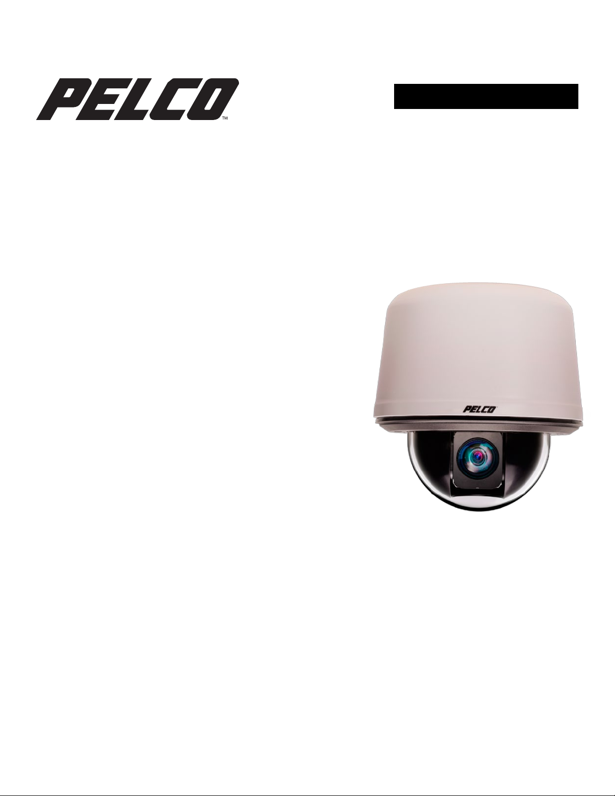
Video Stream Controls
Use the pulldown menu to select a Primary, Secondary, Tertiary, or JPEG video stream.
NOTE: If the Secondary or Tertiary streams have not been configured, they will not be available for
selection. Streams must be configured to use the H264 compression standard. Streams with any
other compression standard will not be available for selection. Video streams can be configured
under the A/V Streams menu.
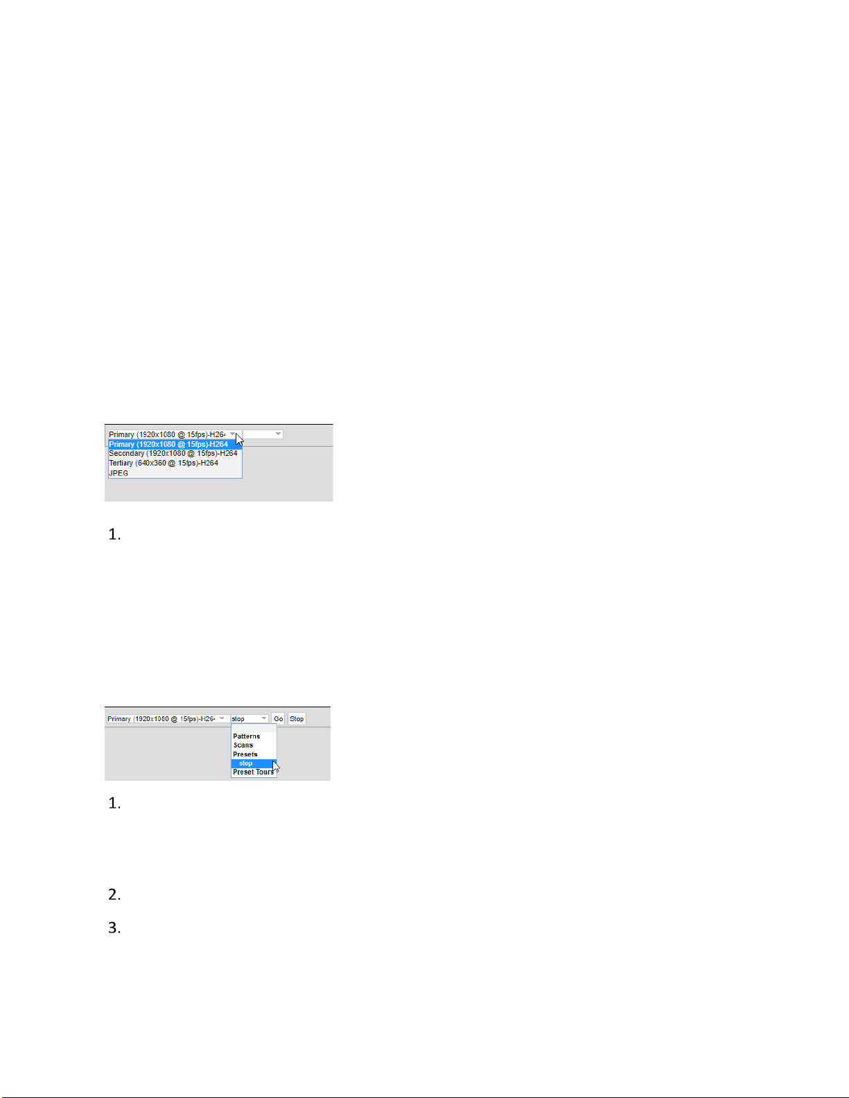
Patterns, Scans, Presets, and Preset Tou r Controls
Click the preset name from the Patterns, Scans, Presets, or Preset Tours list.
NOTE: Only preconfigured patterns are available for selection. Go to the PTZ menu to configure
patterns, scans, presets, and tours.
Click Go to run the pattern.
Click Stop to discontinue the motion.
C6653M | 3/20 7

Focus, Zoom, and Brightness Controls
From left to right, the icons represent:
Zoom Out: Click and hold to zoom out.
Zoom In: Click and hold to zoom in.
NOTE: You can also use the mouse scroll wheel to zoom in and out.
Focus Far: Click and hold to focus on an object far away from the camera.
Focus Near: Click and hold to focus on an object near the camera.
Decrease Brightness: Click and hold to close the iris and darken the image.
Increase Brightness: Click and hold to open the iris and brighten the image.
Viewing, Pan/Tilt, Streaming, and Snapshot Controls
NOTE: PTZ controls are available only after you have logged in to the camera.
From left to right, the icons represent:
Resize Viewing Area: Allows you to zoom in on an area of interest. Click the icon and then
draw a box to designate the area in which you want to center the camera’s field of view
and zoom in.
Center Viewing Area: Engages click-to-center functionality. Click the icon and then click the
location in which you want to center the camera’s field of view.
Pan and Tilt: Engages pan and tilt functions. Click the icon, and then click and drag the
mouse within the video stream to pan and tilt the camera.
Open Stream in New Window: Opens the video stream in an independent window.
Take a Snapshot: Captures a still image from the video stream and saves as a JPEG file.
C6653M | 3/20 8

System Menu
The System menu provides access to the General Settings, Backup and Restore, Firmware, OSDi,
Snapshot Viewer, Storage Management, and Diagnostics pages.
General Settings
Device Name: Configure the name for your device. Names can contain up to 63 alphanumeric
characters. At least one character in the host name must be a letter.
Enable LEDs: Enable or turn off LED camera lights.
Power Priority: Select a priority power supply as either 24v or Power over Ethernet (PoE).
Click Save.
Time Settings
You can set your camera to discover a network time server (NTP) automatically, obtain the address
of your NTP by manual entry, or determine time based on the camera’s internal clock.
Select your Time Server setting as one of the following:
Auto: Allows your camera to discover and synchronize with your network time server (over
IPv4 or IPv6).
Manual: Requires you to provide the address of your network time s e rv e r.
None: When None is selected, the camera date format will default to mm/dd/1970.
Select your Time Zone.
Click Save.
GPS Settings
Use the GPS Settings option to establish the camera’s GPS location.
Manually enter the Latitude, Longitude, and Elevation of the camera.
Click Save.
C6653M | 3/20 9

Generate System Log
If technical difficulties should occur, a System Log might help Pelco Product Support troubleshoot
problems with your camera. You can contact Pelco Product Support at 1-800-289-9100 (USA and
Canada) or +1-559-292-1981 (international).
Click Generate System Log.
Select the location in which to save the log file and Click Save.
Reboot Camera
If you are recording video from your camera, rebooting the camera will cause a gap in video
recording. It is important that you schedule maintenance before restarting the camera.
Click Reboot Camera.
Restore All Camera Defaults
If necessary, you can reset your camera’s settings to their factory defaults.
Click Restore All Camera Defaults and choose one of two options:
Soft Restore: This will reset the camera back to factory defaults with the exception of
network settings. All user settings and customizations will be lost and cannot be recovered.
Hard Restore: This will reset the camera back to factory defaults. All user settings and
customizations and network settings will be lost and cannot be recovered.
Backup and Restore
Go to the System page and click the Backup and Restore tab.
If you accidentally change a setting or need to recover from a factory reset, you can back up and
restore your device configuration. Camera backup files are stored in bin format.
NOTE: The restore feature is not intended to automatically configure multiple devices or to recover
settings following a firmware upgrade.
Backup
Click Generate Backup File.
Click Download Now and specify the directory in which to save your backup file.
Click OK to save the backup file.
C6653M | 3/20 10

Restore
Click Browse to select a file and click OK.
Click Choose File and locate your device’s backup file.
Click “Upload and Restore” to restart the camera and restore your camera settings.
Firmware
System Information
The information settings page includes read-only fields for the Firmware Version, Hardware
Version, Model Number, and Serial Number of the camera. This information is typically required
by Pelco Product Support for troubleshooting purposes.
Firmware Update
To update the firmware:
1. Click Browse to select the firmware you would like to update.
2. Click Upload.
OSDi
The OSDi (Intelligent On Screen Display) allows the camera to show pertinent information as an
overlay within the field of view. You can define up to four overlay rules for OSDi display.
If using the Current Zone Label overlay and multiple zones are in the field of view, the camera will
display the labels in order of size from small to large. If all zones in the field of view are the same
size, the camera will display zone labels in order of creation from old to new.
The camera will display the label in the active zone until the camera’s field of view moves outside
the zone. You can set the Duration of the display as Indefinite or, alternatively, you can define a
number of seconds for the Current Zone Label to be displayed.
OSDi Overlays
Hover in the viewing window to display Upper Left, Upper Center, Upper Right, Middle Left,
Middle Center, Middle Right, Lower Left, Lower Center, Lower Right buttons. Click the button
representing the location in which you want to display the overlay.
Use the Overlay Type pull-down menu to choose between the following overlay types:
C6653M | 3/20 11

Plain Text: Enter a plain text string of your choice.
Camera Name: Display the camera’s name.
Camera Name/Date/Time: Display the camera’s name, date, and time.
Date/Time: Display the camera’s date and time.
Date: Display the camera’s date.
Time: Display the camera’s time.
Event Source: Display an event source on the overlay using a pre-defined Event Source and
associated Handler. Under the Steps to Enable Overlay section, click the Manage Handlers
or Manage Sources link. This will take you to the Handlers and Sources page under the
Events tab in which you can establish or change the settings for Event Source.
PTZ Position: Display the current PTZ Position in the format of Pan°/Tilt°
ZoomX Direction. You can set the Duration of the display as Indefinite or, alternatively, you
can define a number of seconds for the PTZ Position to be displayed on the overlay after
movement stops.
Acquired PTZ Preset: Display the name of a PTZ Preset as defined in the PTZ Preset
Settings. This will only display as long as the preset is acquired by the camera. You can set
the Duration of the display as Indefinite or, alternatively, you can define a number of
seconds for the PTZ Preset Name to be displayed after the Preset is acquired.
Current Zone Label: Display the label of the current zone. If a Current Zone Label has not
been defined, click the Manage Zones link to go to the PTZ Zones tab where you can
establish or create new zones. Under the Duration section, you can select the option to
display the current zone label indefinitely or establish a specific length of time (in seconds)
for which to display the current zone label.
Image: Select an Image File to display by clicking Choose File and traversing to the local
directory in which your image file is stored.
Click Save.
Snapshot Viewer
The Snapshot Viewer displays a list of snapshots when a “Write JPEG to SD Card” handler is
activated. Video is saved to the SD card when a Write Recording to SD Card handler is activated.
The saved video segments can be downloaded from the Snapshot Viewer page.
C6653M | 3/20 12

NOTE: Snapshot Viewer is not available when recording video to local storage. An SD card must be
inserted and configured under Event Handlers.
Select the viewing option by choosing from Select Visible, Deselect Visible, Select All,
Deselect All, Delete Selected, Download Selected, or Refresh List.
Use the Search box to find the snapshot of your choice on the SD card.
Click the Show drop-down to select the number of files to show per page. The default setting
is 15, however up to 100 snapshots can be displayed. Maneuver through the snapshots or
pages using the arrow buttons (<, <<, >, >>).
Storage Management
Device Information
Device Information provides information for the SD card. The following information will be
displayed when an SD Card is properly installed:
Device Type: SD Card
Free Space: Expressed in MB
Total Size: Expressed in MB
Status: Ready to begin recording
NOTE: If there is no SD card in the camera or it was not properly installed, the Status will display
"There is no media in the SD card".
Settings and Actions
Settings and Actions include:
Device Format: Displays the SD card format with the option to reformat the device.
SD Allocation: Establish how much storage to allocate between Edge and Clip storage.
Local Recording
The number of hours of video you can store on the SD card is established with recording bit limits.
A bit rate limit below 1.5 Mbps allows a maximum of 48 hours of video at 30 fps regardless of
resolution. You can increase the maximum available hours of storage by decreasing the frame rate.
Recording State: Check that the recording state is “Ready”.
C6653M | 3/20 13

Record Metadata: Check this box if you want metadata included.
Click REC.
NOTE: The numbers listed above do not include audio. With audio enabled, the number of hours
you can record decreases. The impact is minimal above bit rates of 2.25 Mbps. At bit rates below
2.25 Mbps, the number of hours you can record may drop by approximately 40 percent.
Export Recording
Enter the Start Date and Start Time as well as the End Date and End Time manually into the
Date/Time fields or use the calendar icons to set dates and times.
A menu will show the range of recordings available for export based on your specified dates
and times.
Click Export.
NOTE: Exports are limited to 15-minute clips.
Diagnostics
Go to the Client Connections, Temperature, and Power diagnostic under the System page and
Diagnostics tab.
Client Connections
Client Connections displays the number of active streams by Client Address, Stream type, and
Duration.
Temperature
The Temperature setting displays the current processor temperature along with a graphical display
of the Maximum, Minimum, and Average Processor Temperature (C°) for the current session and
historical sessions.
Power
The current Input Voltage and Power Usage statistics are displayed within the Power section of
the Diagnostics display. Maximum, Minimum, and Average Input Voltage (mV) and Power Usage
(mW) statistics are graphically displayed for the current session and historical sessions.
C6653M | 3/20 14

Network & Security Menu
The Network & Security menu provides access for configuring Network settings, Users & Security,
TLS, Traffic Shaping, 802.1x, SNMP, and Firewall. You have the option of changing ports and
adding firewall rules. By default, your device receives an address over DHCP, and all other network
features are disabled.
Network
Network Hostname
Configure a Network Hostname for your device containing up to 63 alphanumeric characters. At
least one character in the host name must be a letter.
Port Settings
Port Settings establish the ports over which users communicate with the device.
HTTP: Pelco’s VideoXpert™ supports HTTP and HTTPS on any port. The default HTTP port is
80.
NOTE: Do not change the HTTP port when connecting to a legacy Pelco video management
system, as this may prevent you from viewing or recording video from your imaging device.
HTTPS: Set TLS to Optional or Required and install a security certificate before altering the
HTTPS port. The default HTTPS port is 443.
RTSP: Spectra Enhanced 7 devices communicate with video management systems over
RTSP and must use the default port of 554.
Network Interface
IPv4 Settings
By default, cameras are configured to obtain network settings over DHCP. If a DHCP server is not
available, the camera defaults to an address of 192.168.0.20 on a 255.255.255 subnet. If
192.168.0.20 is already in use on the network, the camera will increment the address by one until
it finds an unused address. Set DHCP to Off to configure a static address and manually set the
subnet mask, gateway, and DNS Server settings.
C6653M | 3/20 15

IPv6 Settings
Your camera supports IPv6 configurations in conjunction with IPv4. The device does not support
IPv6-only network deployments. The camera will accept up to sixteen IPv6 addresses, three IPv6
DNS servers, and three IPv6 gateways.
There are two configuration modes for IPv6 address assignment:
Auto: Enables automatic configuration using router advertisement. Additional
configuration can be provided over DHCPv6 (if available on your network). Auto allows you
to manually configure additional address, DNS servers, and gateways.
Manual Only: Provides a link-local address for the device and requires you to manually
configure all other IPv6 address settings for the camera. Manually specified addresses
require a prefix and must be input in the format prefix/IPv6Address. The camera will reject
addresses that do not contain prefix information.
Cameras do not accept multicast, localhost, or undefined IPv6 addresses. Manually specified DNS
servers are not validated by the camera and supersede automatically discovered DNS servers.
Verify your DNS addresses before saving IPv6 settings. Manually specified gateways must be on the
same network as the camera’s IPv6 addresses. Behavior for a gateway that is not on the same
network as the camera’s IPv6 addresses is undefined.
NOTE: Pelco legacy video management systems do not support connections to cameras and
encoders over IPv6.
Users & Security
Features under Users & Security allow you to manage user accounts and establish how your
camera authenticates users.
User Management
Initially, the camera authentication is open for viewing and configuring without a user name and
password. No user accounts exist in the default factory state. Once the Admin role is created and
Local Mode User Management is enabled, your camera will authenticate local user accounts.
If you are a user with Admin permissions, you can configure, edit, and delete local user accounts at
any time. When authenticating users locally, you will assign a role to each individual user. User
permissions are governed by the role assigned to them. When authenticating users remotely, users
will be assigned roles based on their CN and DN assignments.
C6653M | 3/20 16

Your camera supports the following four roles:
Admins: Can access and change all camera settings. They can use all functionality of the
cameras.
Managers: Can access and change all settings, except user permissions. Managers are also
unable to restore factory default settings.
Operators: Can view video and have access to the Live View page controls.
Viewers: Can view video.
Click New User or select the user whose permissions and settings you want to edit.
Select an Access Level for the user.
Provide a user name between 2 and 32 alphanumeric characters for the user. User names are
not case-sensitive and are saved in lowercase characters.
Provide a password between 4 and 64 alphanumeric characters for the user. Passwords are
case-sensitive.
Re-type your password in the appropriate box to confirm your password.
Click Save.
Security
Security options include Open Authentication or Closed Authentication access to the Pelco API or
RTSP/JPEG. A user must be created before the security settings can be changed.
Pelco API
The Pelco API can be used for accessing your device(s). The Open Authentication option allows
users to access a device through the Pelco API without authorization. Authorization for access will
be required when the Closed Authentication option is selected.
RTSP/JPEG
Open or Closed authentication requirements can be set for streaming video via RTSP or JPEG.
NOTE: The Open Authentication setting leaves your camera open to various intrusions and is not
recommended.
C6653M | 3/20 17

TLS
TLS Configuration
TLS Configuration lets you set the TLS mode to either disabled, optional, or required. You must
install or generate a certificate before enabling HTTPS.
The TLS settings include TLS configuration modes and certificate generation. The camera can
generate a certificate signing request (CSR) that can be sent to a certificate authority for a
signature (for example, VeriSign®), or it can generate a self-signed certificate using the Generate
Self-Signed Certificate option.
Disabled: Disables HTTPS communications with the device.
Optional: Requires that you install a signed TLS certificate and enables HTTPS access to the
device, however the device will still be available over HTTP.
Certificate
Select the desired certificate install method and enter the certificate information in the
provided form.
Click Generate Self-signed Certificate or Generate Certificate Request to open a form
including all fields necessary for generating the associated certificate.
Click Upload Certificate to select and upload a certificate.
Traffic Shaping
Your camera can produce large I-frames, resulting in a traffic burst within each group of pictures as
the camera transmits the frame. If your network infrastructure does not have the buffering
capacity to smooth out the traffic, you may experience slow or jittery video. You may want to use
this function if the framerate at your client is significantly lower than you would expect from the
camera.
1. Enable Traffic Shaping with or without bursts, depending on your need.
2. Set the average transmission rate over a 1 ms period over Mbps when enabled without
bursts or a 2 ms period in Mbps when enabled with bursts.
3. If you enabled traffic shaping with bursts, set the maximum size of bursts coming from the
camera in kilobytes.
4. Click Save.
C6653M | 3/20 18

802.1x Security
By default, 802.1x security is off. Cameras support EAP-MD5, EAP-TLS, EAP-TTLS, and EAP-PEAP
protocols.
Select the (EAP) method from the Protocol drop-down.
Provide the authentication information for the EAP method you selected.
Click Save.
SNMP
Your device supports No SNMP Server, SNMP V2c and SNMP V3. The MIB file for your device is
available at www.pelco.com
Configuring SNMP V2c
1. Click SNMP V2c.
2. Provide the community string for your SNMP manager. The default community string is “public”.
3. Provide the Read/Write Community String.
4. Fill in the IP address of the host server.
5. Fill in the Community String.
6. Select the network protocol (NTCIP, Kapsch).
7. Click Save.
Configuring SNMP V3
Click SNMP V3.
Enter the SNMP user name the camera will use to authenticate with the SNMP server.
Select the encryption algorithm for authentication from the Authentication drop-down . If
using MD5 or SHA authentication methods, enter your authentication code in the box
provided.
Select the privacy protocol setting from the Privacy drop-down . If using DES or AES protocols,
enter your privacy key in the box provided.
Enter the host name or IP address of your trap server in the Address box under Trap
Configuration.
C6653M | 3/20 19

Select the network protocol (NTCIP, Kapsch)
Click Save.
Firewall
The text input field requires entry of a valid IP address (IPv4 or IPv6) after first choosing from one
of the firewall options including:
Select On, Allow, or Deny.
NOTE: Incorrect configuration of these settings can result in being locked out of the camera. To
prevent being locked out, establish the mode configuration:
Allow Mode: Ensure workstation IP address/network does appear.
Deny Mode: Ensure workstation IP address/network does not appear.
Enter valid IP address (IPv4 or IPv6).
Click Save.
C6653M | 3/20 20

Imaging
The Imaging menu provides Image Enhancement, Digital Processing, Exposure, WDR, Day/Night
transition, Focus, White Balance, and Window Blanking capabilities.
Restoring Imaging Settings
The Imaging menu contains buttons that allow you to restore your camera’s imaging settings.
Restore Settings to Defaults: Reset your camera’s settings to their factory defaults on the
current webpage.
Restore All Imaging Settings: Reset all of your camera’s imaging settings to their factory
defaults.
General Settings
General Settings control Image Enhancement and Digital Processing features.
Image Enhancement
Backlight Compensation
Use Backlight Compensation to enhance objects in the center of the picture when a bright
backlight causes subjects in the picture to appear dark or silhouetted. Use Off for normal lighting
situations.
Noise Reduction
Noise Reduction adjusts for video noise in the scene.
Off: The camera does not compensate for video noise.
Normal: Adjusts for noise in low-light scenes.
High: Adjusts for a greater amount of noise in low-light scenes.
Defog Mode
The Defog Mode feature allows you to make the subject appear clearer when the surrounding area
of the subject is foggy and low contrast. Choose High, Medium, Low, or Off for this mode. Low is
used for slightly hazy conditions with a minimal amount of correction. High is used for foggier
conditions and maximizes the amount of correction.
C6653M | 3/20 21

Digital Processing
Digital Processing settings adjust the color and detail of captured video. The availability of settings
might change based on your camera model.
Quick Setup: Contains presets for digital processing settings. You can use any of the quick setup
modes as a starting point for custom settings. Changing sharpness, saturation, contrast, or
brightness settings automatically engages the Custom mode.
Normal: A baseline for sharpness, saturation, contrast, and brightness. All the settings are
set to default.
Vivid: A setting that enhances color quality, lightens whites, and darkens blacks.
Custom: Allows you to set your own, unique image quality settings.
Sharpness: Controls the clarity of detail in the scene. Increasing video sharpness increases video
noise.
Saturation: Controls the intensity of colors in the scene.
Contrast: Controls the gradation between the darkest and lightest portions of the scene.
Brightness: Controls the lighting detail of the scene.
Exposure
Exposure settings help ensure that video contains an adequate level of detail and an appropriate
amount of contrast between light and dark values.
Exposure
Select your camera’s exposure Mode.
Auto: Allows you to set maximum exposure time limits and maximum gain settings while
retaining the full range of Day/Night controls.
Max Exposure Time (msec): Establish how long the imaging sensor is exposed to light.
Decreasing the maximum exposure time by reducing motion blurring. This setting is
advantageous in capturing more detailed still images in low light.
Max Gain: Increasing the gain allows for better sensitivity in low-light scenes but also
increases video noise.
Manual: Governs exposure settings based solely on Exposure Time (msec) and Gain
settings. Engaging this setting prevents you from configuring an automatic Day/Night
C6653M | 3/20 22

mode. You should only engage this mode if lighting in the field of view is not expected to
change during operation.
WDR
WDR attempts to compensate for large variances of bright and dark lighting within a scene.
WDR can be turned Off, set to Normal, or set to High. Normal WDR or High WDR is enabled
based upon the maximum framerate.
Optional. Click the Change Settings link to navigate to the A/V Streams page where Maximum
Frame Rate and Aspect Ratio settings can be established.
NOTE: Enabling High WDR is only recommended for scenes needing greater than 120dB dynamic
range. You will see increased noise artifacts in the mid-tones at elevated temperatures.
Electronic Image Stabilization
Electronic Image Stabilization compensates for lens shake and jitter in the recorded video by
smoothing the transition from one frame to another.
Enable Electronic Image Stabilization by choosing On or disable by choosing Off.
NOTE: High WDR and Image Stabilization cannot be used at the same time.
Day/Night
The Day/Night mode controls the IR cut filter, determining whether or not your camera captures
color (day) or black and white (night) video. You can set the Day/Night position manually, but it is
recommended that you engage the auto mode if lighting around your imaging device is expected
to change drastically at any time.
Select the Day/Night Mode.
• Auto: Engages day or night mode based on the Transition Level setting. This allows you to
capture color video (Day) when enough light is available, and automatically switch to black
and white video (Night) when light is unavailable.
• Manual: Requires you to choose a Day or Night mode. Day captures color video whereas
Night captures grayscale video.
(Optional) Set your camera’s Transition Level to determine when the camera switches from
Day to Night mode. The Lighter setting changes modes at higher lux values, while the Darker
settings change modes at lower lux values.
C6653M | 3/20 23

(Optional) Set the Transition Detect Time (sec) to determine the frequency at which the
device checks for adequate light to transition to day mode or night mode.
Focus
Select the Focus mode.
Auto: Automatically back-focuses the camera on the subject in the center of the scene.
Manual: Locks the camera’s focus at a specified position. Manual focus is recommended
Sure Focus: Causes your camera to auto focus when pan, tilt, and zoom (PTZ) operations
only for indoor applications with a single, unchanging light source or when using analytics.
are complete or if the IR cut filter changes state. When your camera achieves an auto focus
lock, auto focus is turned off and the focal position will remain until the next PTZ operation.
If 30 seconds pass without an auto focus lock, your camera will retain its focal position until
the next PTZ action.
Focus Trace: Enables your camera to use a focus trace curve when zooming based on the
distance to ground-level targets in the scene. Distance to ground-level targets is
determined by the Install Height setting. If Auto Focus is disabled, your camera will not
perform auto-focus operations but will perform focus trace corrections when the tilt angle
of your camera changes.
Min Focus Distance (m): Default setting of 10m (meters) improves low light auto focus.
Change the Min Focus Distance (m) to an expected minimum distance that the camera will
need to focus on.
White Balance
Each Sensor has its own white balance settings. Auto mode is the default setting for each sensor.
Selecting Manual mode allows you to adjust White Balance settings for the sensor.
Select a White Balance mode:
Auto: The recommended setting for most lighting conditions. It has a color temperature
range from 7,500K to 2,500K. It can be used to properly adjust white balance scenes
illuminated by daylight to warm white sources.
Auto Tracking White: Has the largest color temperature range.
Cool White: A fixed white balance mode for cooler (bluer) sources such as true daylight,
daylight fluorescent, white light LEDs, or metal halide sources.
C6653M | 3/20 24

Warm White: A fixed white balance mode for warmer (more yellow) sources such as
incandescent, tungsten-halogen, warm white compact florescent, or LED lighting.
Manual: Allows manual adjustment of the red and blue range. This may be helpful in areas
where lighting does not change, such as inside a casino or mall. Move the Red and Blue
sliders to change color levels.
Window Blanking
Window Blanking is used to conceal user-defined privacy areas. A blanked area appears on the
screen as a solid gray window. The camera can handle up to eight blanked windows as long as the
total blanked area does not exceed 50 percent of the field of view.
NOTE: Window-blanking regions will not scale proportionally with changes in zoom. Set the zoom
level for the camera before defining window-blanking regions.
Window Blanking
To enable Window Blanking, click On.
NOTE: If you receive a Calibration Incomplete message, perform the following:
Click Calibration.
Click to center on an object to be covered and click OK.
Use your cursor to draw the region to be blanked and click OK.
Redraw the same region to be blanked and click OK.
You should now see the Calibration Completed message.
Click Done.
If necessary, maneuver the video preview to find the region you want to blank.
Drag the mouse across the video area that you want to blank. Select an existing blanking
region to delete or edit its size and position. You have the option of drawing up to eight
window blanking levels. Each window will be designated with a unique color.
Edit Window
The Edit Window displays each blanking window you have set.
Select a window in the Edit Window or in the Preview Display to move or resize the blanking
window.
C6653M | 3/20 25

PTZ Menu
The PTZ Menu provides configuration options for Positioning, Presets, Preset Tours, Patterns,
Scans, PTZ Zones, and Pelco Camera Link.
Positioning
Digital Zoom
Enable Digital Zoom by clicking On. Click Off to enable optical zoom.
Freeze Frame
Freeze Frame is a technique that stops the moving image of the film and holds it motionless on
screen.
Click On to enable the Freeze Frame control.
Pan/Tilt Speed Control
Select the Pan/Tilt Speed Control type:
A: Linear: Pan and tilt speeds accelerate at a fixed rate.
B: Exponential: Pan and tilt speeds accelerate at a rate corresponding to the length of time
for which a user engages pan and tilt controls. The longer a user engages pan and tilt
controls, the faster the camera will pan and tilt.
Proportional Velocity: Automatically reduces pan and tilt speeds proportional to the
camera’s zoom level.
Auto Flip: Allows the dome to rotate 180 degrees when the tilt is pointing straight down
(e.g. –90 degrees tilt angle).
PTZ Resume: Allows the dome to recover the last PTZ action requested before the camera
loses power. The camera will resume the previous action upon start-up.
Max Zoom Speed: The numeric values that can be selected using the slider bar represents
a percentage of the maximum zoom speed. Values range from 10 to 100. For example,
setting the slider to 50 for 50% tells the camera to zoom at half the speed.
C6653M | 3/20 26

Pan Center Point (Azimuth Zero)
The Pan Center Point determines the zero point for pan operations. Setting a new center point
automatically adjusts Pan Limit Stop settings to account for the new center point.
To determine the current center point, click Go To Pan Center Point.
To establish a new pattern center point, use the cursor or joystick to pan to the new center
point location and click Set New Pattern Center Point.
Click Restore Default Center Point to restore the camera’s default center position.
Limit Stops
Limit Stops allow you to limit the range of motion for your camera. Pan and tilt limit values are
provided in degrees.
Click Start Configuring Limits.
NOTE: During configuration, limits are disabled on the camera. You must complete the
configuration process before limits will be enabled.
Configure the left and right pan limits and the top and bottom tilt limits. You can provide a
value, in degrees, for each limit, or click Get Current Pan/Tilt to retrieve the current value from
the video preview window.
Click Save Limits.
To remove all limits on the camera and restore default values, click Remove Limits.
Presets
A preset is a camera position that you can configure and call as a single command, allowing users
to quickly move the camera to common positions. To establish a new preset:
Click New in the Presets window or select the preset you want to edit.
Enter a preset name in the New field when creating a new preset.
Select the Focus Lock mode:
• On: The camera’s focus settings are saved with the preset and are called with the preset.
This ensures that the camera uses the expected focal point any time the preset is selected.
• Off: The preset does not retain focus settings. This mode requires the camera to use
current focus setting when the preset is selected.
C6653M | 3/20 27

If an operator has changed the focus of the camera before the preset is selected, it is possible that
the camera will be out of focus when the camera displays the preset position later. Turn on Focus
Lock to avoid this problem.
Position the camera using the pan and tilt controls.
Adjust the zoom and focus controls as necessary.
Click Save.
Preset Tours
You must configure presets before adding them to a preset tour. A Preset Tour is a series of presets
through which your camera will cycle. You can configure the length of time for which the camera
will remain at each preset position in the tour.
PTZ Tours
Existing tours will be listed in the PTZ Tours window with the options to Run, Delete, or create a
New tour.
Click the New button or select the preset tour you want to edit.
Enter a preset name in the Tour Name field when creating a new PTZ tour.
Click and drag presets to the “To ur workspace” section of the page.
Set the dwell time for each preset to establish the length of time (in minutes or seconds) the
camera will remain at a preset position before engaging the next preset in the t ou r.
Set the transition speed for each preset tour.
Click >> to the right of the “Transition preview” to review the tour.
Click Save.
Patterns
A pattern uses the path of motion recorded by the operator during configuration of the pattern.
This is different from a Preset Tour in that a preset tour begins at one spot and ends at another,
using the most direct path between them.
PTZ Patterns
To create a new PTZ pattern:
C6653M | 3/20 28

• Click New.
• In the Create New Pattern panel, type in a name for the pattern.
• Click Create Pattern and Start Recording.
• (Optional) Add a Scan, a Preset, or a Preset Tour as part of the pattern.
• Click Run to run the pattern and Stop to end the process.
To run an existing PTZ pattern:
Select the name of the existing pattern from the list in the PTZ Patterns area.
Click Run to start the pattern.
Click Stop to stop the pattern.
(Optional) Click Re-record to record over the current configuration and then click OK.
To rename an existing pattern:
Select the name of the existing pattern from the list in the PTZ Patterns area.
Type the new name into the Name field in the Rename Pattern panel.
Click Save.
To delete an existing pattern:
Select the name of the existing pattern from the list in the PTZ Patterns area.
Click Delete.
Click OK in the confirmation dialog box.
Scans
A Scan is a pan movement between two limits at a defined speed and a defined dwell time at each
frame.
• A Scan configured with limits will change direction when a limit is reached. When
configured without limits, or the limits are set to the same point, the scan will pan 360
degrees until interrupted by a manual movement or a stop.
• A scan can be started at any tilt angle and will maintain that tilt angle throughout the pan
scan.
To create a new PTZ scan:
C6653M | 3/20 29

Click New.
In the New Scan area of the window, type in a name for the scan.
(Optional) Type in a value for the Left Pan Limit, and then click Save as Left Pan Limit.
(Optional) Type in a value for the Right Pan Limit, and then click Save as Right Pan Limit.
Type in a Speed expressed in Degrees/Seconds.
Type in a Dwell Time expressed in Seconds.
Click Save.
Select the newly created scan from the PTZ Scans area.
Click Run to start the scan.
Click Stop to end the scan.
To edit a scan
Select the name of the existing scan from the list in the PTZ Scans area.
Use the Scan Name field to enter the name of the scan you wish to edit.
(Optional) Type in a value for the Left Pan Limit, and then click Save as Left Pan Limit.
(Optional) Type in a value for the Right Pan Limit, and then click Save as Right Pan Limit.
Type in a Speed expressed in Degrees/Seconds.
Type in a Dwell Time expressed in Seconds.
Click Save.
NOTE: Scan limits are optional. Scan limits will be disabled if the Left and Right Pan limits are set to
the same value.
To run an existing PTZ scan:
Select the name of the existing scan from the list in the PTZ Scans area.
Click Run to run the existing scan.
Click Stop to stop the existing scan.
Click Delete, if you wish to delete an existing scan.
C6653M | 3/20 30

PTZ Zones
When the camera is in view of a zone, the zone name will appear as an Intelligent On Screen
Display (OSDi). Click Manage OSDi Settings to configure the Current Zone Label on the OSDi page
and enable this feature.
To create a new PTZ Zone:
Click New Zone.
Type a new Zone Name within the New Zone section.
Use the pan, tilt, and zoom controls to select the Zone Position.
Click Save.
To edit an existing zone:
• Select the zone from the PTZ Zones area.
• Make the desired edits in the Edit Zone area.
• Click Save.
To delete an existing zone:
Select the zone from the PTZ Zones area.
Click Delete Zone.
Pelco Camera Link
The Pelco Camera Link automatically tracks objects of interest. You can link Pelco’s Optera™ and a
nearby, mounted Spectra Enhanced camera. Optera™ provides seamless panoramic coverage for
total situational awareness while the Spectra Enhanced with 30x optical zoom provides detail and
automatic object tracking.
When Auto tracking is enabled, Pelco Camera Link acts as an automatic PTZ operator. Pelco
Camera Link uses the analytic information from Optera™ to enable point and zoom so the camera
will follow moving objects in the scene.
Setup
Establish a connection with Optera™ by specifying the address and credentials of the Optera
system. Enter the IP Address, Username, and Password.
C6653M | 3/20 31

Alternatively, you can click the Advanced button to specify the IP Address, Username,
Password, SSL/TLS, and HTTP Port parameters.
Click Connect to link the camera with the Optera™ system.
Click Disconnect to disconnect the link between the camera and the Optera™ system.
Configure the Optera™ Analytics by clicking Go to Optera Analytics™ Page. Once you are at
the Pelco Camera Link configuration page, you can establish a connection by activating and
enabling '2-Camera Tracking' as an Optera™ Analytic profile, and then return to this page and
refresh.
Calibrate the connected cameras by clicking the Calibrate button. Doing so will calibrate the
connected cameras so that they know where they are relative to one another.
C6653M | 3/20 32

A/V Streams Menu
A/V Streams provides access to Preset Configurations, Video Configurations, Audio
Configurations, RTP Settings, and Smart Compression settings for your device’s video and audio
streams.
Video Presets
Video Presets are fully-configured video configurations that offer a good balance of video
performance to bandwidth. These presets may also be used as a starting point for a custom
configuration. Video preset configurations may vary depending on the camera model.
Preset Configuration
Current Configuration (custom): This box displays user specified (custom settings) for primary,
secondary, and tertiary streams. Alternatively, select your desired Preset Configurations of High,
Medium, or Low and click Save.
NOTE: Details for Preset Configuration are displayed in the user interface next to the desired
profile.
Preset Configurations include:
High: Primary Stream H264, 30 IPS, 1920x1080, 6000 kbps | Secondary Stream H264, 30
IPS, 1920x1080, 6000 kbps | Tertiary Stream H264, 30 IPS, 640x360, 1250 kbps
Medium: Primary Stream H264, 15 IPS, 1920x1080, 3850 kbps | Secondary Stream H264,
15 IPS, 1920x1080, 3850 kbps | Tertiary Stream H264, 15 IPS, 640x360, 900 kbps
Low: Primary Stream H264, 15 IPS, 1280x720, 2400 kbps | Secondary Stream H264, 10 IPS,
1280x720, 2050 kbps | Tertiary Stream H264, 10 IPS, 640x360, 600 kbps
Video Configuration
Custom Video Stream Configuration
Custom Video Stream Configuration contains settings for customizing your camera’s primary,
secondary, and tertiary video streams. Each stream can be configured independently, although the
Aspect Ratio and Maximum Frame Rate settings will limit the options available for the remaining
setting and depending on the processing demands of your stream settings.
C6653M | 3/20 33

By default, all fields under Video Configuration are populated with settings from your Video
Presets. You can clear all fields or use the default settings as a starting point for your custom
stream.
Set the Maximum Frame Rate and Aspect Ratio settings.
• Maximum Frame Rate: The maximum number of video frames contained per second.
Higher values result in higher quality video with less flicker but consume more bandwidth.
• Aspect Ratio: The ratio of height to width of the video frame.
Configure the following video stream settings:
Stream Name: This setting is typically Primary, Secondary, or Tertiary, however you can
enter any stream name of your choosing.
Enable: This setting provides the ability to turn any stream ON or OFF. Select Enable from
the drop down menu to turn the stream on or Disable to turn it off.
Compression Standards: Available compression standards include MJPEG, H.264, and
H.265.
H264: Compression standard used in high-definition video players such as Blu-ray™ and
HD-DVD. H.264 is the most processor-intensive compression.
H.265: An improvement of H.264 that provides better compression efficiency while
improving image quality and lowering processor workload.
MJPEG: Provides the least impact on the camera's processor, but it requires the most
bandwidth.
Resolution: The quality of the video stream, rendered in pixels for both width and height.
Higher values result in greater video quality but consume more bandwidth.
Image Rate: The number of frames per second (fps) available for the video stream
configuration. Available image rates depend upon the model of the device that you are
using.
Bit Rate: The quality of the video stream, rendered in kilobits per second. Higher values
result in greater video quality but consume more bandwidth.
I-Frame Interval: Determines the number of partial frames that occur between intra-coded
frames (I-frames) in your video stream. I-frames are complete images, used as a reference
for change. Following an I-frame, the camera will capture and encode only video data in the
scene differing from the I-frame until the next I-frame.
C6653M | 3/20 34

NOTE: The I-Frame Interval setting is only available for H.264 and H.265 video streams.
Increasing the I-frame interval can improve video compression rates and reduce the size of
video data; however, higher values are recommended only for highly-reliable networks.
Profile: Defines the subset of bit stream features in an H.264 or H.265 stream, which
includes color reproduction and additional video compression. It is important to select a
profile that is compatible with your recording device(s) in order to ensure that your
camera’s video stream can be decoded and viewed.
• Main: An intermediate profile with a moderate compression ratio. This profile is
compatible with most recorders and uses fewer bits to compress video than the baseline
profile. The main profile supports I-frames, P-frames, and B-frames.
• High: A complex profile with a high compression ratio. This is the primary profile for high-
definition television applications. The high profile supports I-frames, P-frames, and B-
frames.
QoS (DSCP) Codepoint: A mechanism for prioritizing network traffic. This setting is
available with H.264 and H.265 compression standards. Your network must be QoS-aware
to take advantage of this setting.
Endura Signing: Endura signing is a technology designed to prevent the tampering of video
and ensure video authenticity for use in legal proceedings. Only exported video is validated
in the Pelco export player when the user clicks on the "Authenticate" button. Live View is
not validated. This setting is available only with H.264 and MJPEG compression standards.
Rate Control: Determines the bit rate and quality of each frame in the H.264 or H.265 video
stream. Rate control settings are a compromise between image quality and the resources
required for video storage. The availability of rate control settings depends upon the model
of the camera that you are using.
CBR: The constant bit rate (CBR) streams video at a fixed number of bits per second. CBR
uses the full capacity of the bit rate setting for scenes with or without motion. Video is
always streamed at the user bit rate setting.
CVBR: The constrained variable bit rate (CVBR) provides high-quality video and long
recording time of variable bit rate while limiting variations in recording capacity
consumption.
NOTE: When you change video stream configuration settings, the camera automatically
adjusts the bit rate. Choosing a bit rate below the camera’s automatic setting might reduce
video quality and limit stream configuration options.
C6653M | 3/20 35

Audio Configuration
You can only enable audio through the primary video stream. By default, Audio is disabled.
NOTE: Audio and video might not be synchronized when viewing the primary stream through a
browser. You might experience up to a 3-second delay in video when viewing the primary stream
with audio enabled.
Enable Audio
Select your audio device.
• Native Line In: This setting applies only to products with built-in audio support and enables
audio from a microphone connected to the audio-in connector.
Select your sample rate which is the quality of the audio stream (measured in hertz per
second).
Choose PCMU, PCMA, or PCM16 Encoding type.
Set the Input Level. Input sensitivity is measured on a scale from 0 to 100 (low to high).
Click Save.
RTP Settings
Multicast
Multicast: A multicast stream sends video data to multiple users from the same transmission. Each
multicast user connecting to the camera consumes no additional processing power.
You can set static multicast addresses and ports for your camera’s primary, secondary, tertiary, or
audio streams. Automatically-assigned multicast addresses are confined to the 239.x.x.x block in a
scheme matching your IP address and network settings by default. You can determine the
automatically-assigned multicast address(es) for your camera from the RTP .
Enter static multicast addresses and ports for your streams as necessary.
Set the Time to Live (TTL) for each stream. TTL is the number of routers the stream can pass
through before it expires.
Choose Always Multicast this stream if you want to eliminate the need for a client to connect
to the camera to initiate a stream. When enabled, the camera begins sending the multicast
stream when it starts up, without requiring initiation from a client.
Click Save.
C6653M | 3/20 36

TCP/IP
You can adjust the maximum transfer unit size to adjust to your network’s constraints.
Set the Max Transfer Unit (MTU) size.
Click Save.
NOTE: The camera will automatically reboot after clicking Save.
Smart Compression
Pelco Smart Compression Technology lowers bandwidth and storage requirements while retaining
image quality and critical information for forensic purposes. Benefits include reduced storage
capacity requirements, high resolution, and upgradable firmware to protect your investment
without sacrificing quality down the road.
To work correctly, gathering bitrate statistics requires the date and time to be set correctly. If you
have not set your time zone, you will receive an “Inaccurate Date and Time” message. Date and
time can be set in General Settings.
Prior to establishing settings for Pelco Smart Compression, use A/V Streams to configure the video
and audio streams for the camera.
Configuring Smart Compression
Settings and Short Term-Graph
Select Settings and Short-Term Graph.
Select your Smart Compression Level:
• Off: No bitrate reduction.
• Low: No visible effect on video quality in most scenes.
• Medium: Visible effect on video quality in some scenes.
• High: Video quality degraded in many scenes.
(Optional) Enable Dynamic GoP Length. If you want to place an upper limit on the Dynamic
GoP length, set the Optimal Maximum GoP Length for each stream.
NOTE: The option to establish the Dynamic GoP Length is enabled when compression levels are
set to Low, Medium, or High.
C6653M | 3/20 37

(Optional) Set the Optional Maximum GoP Length for your streams if you want to establish
the upper limit of the Dynamic GoP setting.
Dynamic GOP Length: By enabling a dynamic Group of Pictures (GOP), the number of I-frames are
automatically reduced in scenes with minimal motion. Based on the complexity of scenes and the
amount of motion occurring, such as in a storage room that has limited activity, up to 70%
bandwidth savings can be achieved.
The option to establish the Dynamic GOP Length is enabled when compression levels are set to
Low, Medium, or High. Dynamic GOP allows the camera to update picture groups depending on
scene composition and motion. A dynamic GoP can further reduce bit rates produced by the
camera by allowing the camera to increase the GOP length when there is little action in the scene.
For each video stream, you can enable Dynamic GOP Length as well as establish an Optional
Maximum GOP Length. GOP length will change dynamically based on variable conditions that your
camera may be monitoring.
Configuring Long-Term Rate Control
Set Long-Term Rate Control to ensure storage does not exceed a specific size.
Run the camera for multiple days which should represent the number of times the length of
the observation period will be used.
Select Long-Term Rate Control.
Select the Video Stream to which you will apply the settings.
Select the Bitrate Units: either total kbps or Gbytes/day.
In the Long-Term Rate Controls area:
Click Enabled to enable the Controls.
NOTE: You can Disable the Controls at any time.
Use the slider bar to select the Average Bitrate Limit, type in a value, or click Copy to
Slider.
Use the slider bar to select the Observation Period in Days, or type in a value.
Click Save.
To view the Long-Term Graph for either stream:
Select either the Primary or Secondary Video Stream.
C6653M | 3/20 38

Select the Bitrate Units in kbps or Gbytes/day.
In the Long-Term Graph data viewer, click Update. The graph helps you understand how
much storage the camera will use.
(Optional) Delete Long-Term Data for Secondary or Primary.
C6653M | 3/20 39

Events
Events provides access to camera event and analytic settings and include Source, Handlers,
Analytic Configuration, and Event Stream. An event is a user-defined occurrence, consisting of a
Source and a Handler. A Source defines the trigger for an event, and a Handler defines the action
your camera will take when the event source occurs.
When configuring a Source, you can link the source to multiple handlers, thus providing multiple
outcomes for the event. When configuring a Handler, you can link the handler to multiple sources,
providing a single outcome for multiple events.
Analytics are specialized event sources that are triggered by the user-defined behaviors or
scenarios occurring within your imaging device’s field of view. Analytics are compatible with
VideoXpert® or third-party systems that support events using ONVIF or Pelco’s API.
NOTE: The analytic behaviors available for your camera are dependent on your model and
firmware version.
Sources
An event source defines the trigger for an event, something that must occur before your camera
takes action (defined by a handler). You can configure Alarm, Analytics, Timer, System, Park
Action, and Network Loss events.
Configuring an Alarm Event Source
Alarm Event Source triggers an event upon a signal from external signaling devices such as a door
contact or a motion detector.
Click New Source or select the source you want to edit.
Provide a name, between 2 and 23 alphanumeric characters for the event source in the Name
box.
Select Alarm from the Type drop-down. This alarm will be triggered when an event occurs.
Set the dwell time for the alarm between 1 and 25 seconds. Dwell time is the amount of time
that the source will remain active during an alarm event.
Select the polarity of your alarm input (normally open or closed).
Select either True or False from the Supervised drop-down .
Click the Handler that determines what action occurs in response to the alarm event.
C6653M | 3/20 40

Click Save.
Configuring an Analytic Event Source
Analytic Event Source triggers an event when a behavior defined by a video analytic occurs.
Check New Source or select an existing source you want to edit.
Provide a name, between 2 to 23 alphanumeric characters, for the event source in the Name
box.
Select Analytics from the Type drop-down menu.
(Optional) If available, select the handler(s) that you want to associate with this source.
Click Save.
Configuring a Timer Event Source
Timer Event Source triggers an event at specified intervals of time.
Click New Source or select the source you want to edit.
Provide a name, between 2 and 23 alphanumeric characters, for the event source in the Name
box.
Select Timer from the Type drop-down.
Configure the frequency of the event.
(Optional) If available, select the handler(s) that you want to associate with this source.
Click Save.
Configuring a System Event Source
System Event Source triggers an event when your camera boots.
Click New Source or select the existing source you want to edit.
Provide a name, between 2 and 23 alphanumeric characters, for the event source in the Name
box.
Select System Type drop-down.
(Optional) If available, select the handler(s) that you want to associate with this source.
Click Save.
C6653M | 3/20 41

Configuring a Parking Action
Park Action Source triggers an event when the camera stops moving after a defined interval.
Click New Source or select the source you want to edit.
Provide a name, between 2 and 23 alphanumeric characters, for the event source in the Name
box.
Select Park Action Type drop-down.
Enter the number of seconds to wait after the camera stops before triggering. The dwell time
must be greater than 30 seconds.
(Optional) If available, select the handler(s) that you want to associate with this source.
Click Save.
Configuring a Network Loss Event Source
Network Loss Event Source triggers an event if the connection to a network is lost.
Click New Source or select the source you want to edit.
Provide a name, between 2 and 23 alphanumeric characters, for the event source in the Name
box.
Select Network Loss from Type drop-down.
Enter the IP address that will be monitored for ping requests
Establish the frequency, in minutes, which the network device is contacted
Click Save
Deleting an Event Source
Select the source that you want to delete.
Click Delete Source to remove the event source.
Handlers
Event Handlers are the actions that your camera takes when an event source occurs. Handlers
include Send Email, Upload JPEG to FTP Server, Write JPEG to SD Card, Run Pattern, Go to Preset,
Run Tour, Run Scan, Open/Close Relay, Display Overlay, Play Audio, Write Recording to SD Card,
C6653M | 3/20 42

and Upload Recording to FTP Server. The availability of handlers might change based on your
camera model.
Configuring an Event Handler: Send Email
You must have provided your camera with the address of an SMTP mail server from General
Settings (available under the System ) for your camera to send email notification for events.
The Send Email event handler sends an email from your camera when a source event is triggered.
Click the New button or select the handler you want to reconfigure.
Provide a name, between 2 and 23 alphanumeric characters, for the event handler in the
Name box.
Select Send Email for the handler Type.
Provide the necessary information for your email in the To, From, Subject, and Message boxes.
(Optional) Select the JPEG Snapshot box if you want to send a JPEG snapshot as an attachment
to the email.
(Optional) Select the Attach Raw Event Data box if you want the email to include extra data
about the event. For example, select this box if the event is triggered by an alarm and you
want to receive data about the state, time, or type of alarm.
(Optional) Set time filters to determine the days and times during which the handler will be
active. If you do not select any filters, the handler will remain active at all times. All time values
must be formatted in 24-hour notation.
Select the source(s) that you want to trigger this event handler.
Click Save.
Configuring an Event Handler: Upload JPEG to FTP Server
This event handler captures and uploads a JPEG to an FTP server when an event source is
triggered. JPEG files are named according to the date and time at which they are recorded;
although, you can determine the order of factors in the date-and-time filename.
Click New Handler or Select the handler you want to reconfigure.
Provide a name, between 2 to 23 alphanumeric characters, for the event source in the Name
box.
Select the Upload JPEG to FTP Server handler type.
C6653M | 3/20 43

Provide the address of your FTP server in the Server box.
Provide the credentials the camera will use to authenticate with the FTP server; the user name
must be between 1 and 32 alpha- numeric characters, and the Password must be between 4
and 16 alphanumeric characters.
Provide the path in which to store JPEG files on your FTP server in the Base Path box.
Select the File Name for your JPEG snapshots. JPEG files are named according to the date and
time at which they are recorded.
(Optional) Set time filters to determine the days and times during which the handler will be
active. If you do not select any filters, the handler will remain active at all times. All time values
must be formatted in 24-hour notation.
Select the source(s) that you want to trigger this event handler.
Click Save.
Configuring an Event Handler: Write JPEG to SD Card
This event handler captures and uploads a JPEG to an SD card when an event source is triggered.
JPEG files are named according to the date and time at which they are recorded; although, you can
determine the order of factors in the date-and-time filename.
Click New Handler or Select the handler you want to reconfigure.
Provide a name, between 2 to 23 alphanumeric characters, for the event handler in the Name
box.
Select the Write JPEG to SD card handler type.
Select the File Name for your JPEG snapshots. JPEG files are named according to the date and
time at which they are recorded.
(Optional) Set time filters to determine the days and times during which the handler will be
active. If you do not select any filters, the handler will remain active at all times. All time values
must be formatted in 24-hour notation.
Select the source(s) that you want to trigger this event handler.
Click Save.
Configuring an Event Handler: Run Pattern
This event handler executes a Run Pattern when an event source is triggered.
C6653M | 3/20 44

Click New Handler or Select the handler you want to reconfigure.
Provide a name, between 2 to 23 alphanumeric characters, for the event handler in the Name
box.
Select the Run Pattern handler type.
Select the Pattern for your Run Pattern handler.
(Optional) Set time filters to determine the days and times during which the handler will be
active. If you do not select any filters, the handler will remain active at all times. All time values
must be formatted in 24-hour notation.
Select the source(s) that you want to trigger this event handler.
Click Save.
Configuring an Event Handler: Go to Preset
This event handler executes a Preset Tour when an event source is triggered.
Click New Handler or Select the handler you want to reconfigure.
Provide a name, between 2 to 23 alphanumeric characters, for the event handler in the Name
box.
Select the Preset handler type.
Select the Preset for your Go to Preset handler.
(Optional) Set time filters to determine the days and times during which the handler will be
active. If you do not select any filters, the handler will remain active at all times. All time values
must be formatted in 24-hour notation.
Select the source(s) that you want to trigger this event handler.
Click Save.
Configuring an Event Handler: Run Tour
This event handler executes a Run Tour when an event source is triggered.
Click New Handler or Select the handler you want to reconfigure.
Provide a name, between 2 to 23 alphanumeric characters, for the event handler in the Name
box.
Select the Run Tour handler type.
C6653M | 3/20 45

Select the Tour for your Run Tour handler.
(Optional) Set time filters to determine the days and times during which the handler will be
active. If you do not select any filters, the handler will remain active at all times. All time values
must be formatted in 24-hour notation.
Select the source(s) that you want to trigger this event handler.
Click Save.
Configuring an Event Handler: Run Scan
This event handler executes a Run Scan when an event source is triggered.
Click New Handler or Select the handler you want to reconfigure.
Provide a name, between 2 to 23 alphanumeric characters, for the event handler in the Name
box.
Select the Run Scan handler type.
Select the Select the Scan for your Run Scan handler.
(Optional) Set time filters to determine the days and times during which the handler will be
active. If you do not select any filters, the handler will remain active at all times. All time values
must be formatted in 24-hour notation.
Select the source(s) that you want to trigger this event handler.
Click Save.
Configuring an Event Handler: Open/Close Relay
This event handler executes an Open/Close Relay when an event source is triggered.
Click New or select the handler you want to reconfigure.
Provide a name, between 2 and 23 alphanumeric characters, for the event handler in the
Name box.
Select Open/Close Relay.
Select the individual relay you want to trigger when an event occurs from the Relay drop-
down.
Set the Relay Mode to Pulse or Trigger based on the type of relay being used.
C6653M | 3/20 46

Use the On Time controls to set the amount of time the relay will remain open, up to 200
seconds.
Use the Off Time controls to set the amount of time the relay will remain closed, up to 200
seconds.
Set the Pulse Count for the relay. The pulse count is the number of relay pulses (number of on
and off cycles).
(Optional) Set time filters to determine the days and times during which the handler will be
active. If you do not select any filters, the handler will remain active at all times. All time values
must be formatted in 24-hour notation.
If available, select the source(s) that you want to trigger this event handler.
Click Save.
Configuring an Event Handler: Display Overlay
The Display Overlay event handler displays an OSDi of the source name when any connected
source is triggered. When using the Event Source overlay and the Display Overlay handler, the
camera will push any connected event sources to the OSDi when triggered.
NOTE: Overlay configuration settings are available on the OSDi page.
Click New Handler or select the handler you want to reconfigure.
Provide a name, between 2 and 23 alphanumeric characters, for the event handler in the
Name box.
Select the Display Overlay handler type.
(Optional) Set time filters to determine the days and times during which the handler will be
active. If you do not select any filters, the handler will remain active at all times. All time values
must be formatted in 24-hour notation.
Select the source(s) that you want to trigger this event handler.
Click Save.
Configuring an Event Handler: Play Audio
This event handler plays an audio file when an event source is triggered.
Click New or select the handler you want to reconfigure.
C6653M | 3/20 47

Provide a name, between 2 and 23 alphanumeric characters, for the event handler in the
Name box.
Select Play Audio from the Type drop-down.
Click Browse and select a valid .WAV file to be played when the event occurs.
(Optional) Set time filters to determine the days and times during which the handler will be
active. If you do not select any filters, the handler will remain active at all times. All time values
must be formatted in 24-hour notation Select the source(s) that you want to trigger this event
handler.
Select the source(s) that you want to trigger this event handler.
Click Save
Configuring an Event Handler: Write Recording to SD Card
This event handler captures and uploads video to an SD card when an event source is triggered.
Video files are named according to the date and time at which they are recorded; although, you
can determine the order of factors in the date-and-time filename.
Click New or select the handler you want to reconfigure.
Provide a name, between 2 to 23 alphanumeric characters, for the event source in the Name
box.
Select Write Recording to SD Card as the event type.
Enter Pre-Event Buffer duration, Post-Event Buffer duration, and Size Limit for the Recording
to be written for the SD Card.
Select the File Name for your JPEG snapshots. JPEG files are named according to the date and
time at which they are recorded.
(Optional) Set time filters to determine the days and times during which the handler will be
active. If you do not select any filters, the handler will remain active at all times. All time values
must be formatted in 24-hour notation.
Select the source(s) that you want to trigger this event handler.
Click Save
C6653M | 3/20 48

Configuring an Event Handler: Upload Recording to FTP Server
This event handler captures and uploads a recording to an FTP server when an event source is
triggered. Recording files are named according to the date and time at which they are recorded;
although, you can determine the order of factors in the date-and-time filename.
Click New or select the handler you want to reconfigure.
Provide a name, between 2 to 23 alphanumeric characters, for the event source in the Name
box.
Select the Upload Recording to FTP Server handler type.
Provide the address of your FTP server in the Server box.
Provide the credentials the camera will use to authenticate with the FTP server; the user name
must be between 1 and 32 alpha- numeric characters, and the Password must be between 4
and 16 alphanumeric characters.
Provide the path in which to store the video files on your FTP server in the Base Path box.
Select the File Name for your video files (named according to the date and time at which they
are recorded).
(Optional) Set time filters to determine the days and times during which the handler will be
active. If you do not select any filters, the handler will remain active at all times. All time values
must be formatted in 24-hour notation.
Select the source(s) that you want to trigger this event handler.
Click Save.
Deleting an Event Handler
Select the handler that you want to delete.
Click Delete Handler.
C6653M | 3/20 49

Analytic Configuration
The Analytic Configuration section allows you to analyze the camera’s field of view to detect and
trigger events or alarms when specific activity occurs. Analytic configurations are contained within
Profiles that define the zones in which analytic behaviors are deployed. You must create a profile
to enable analytic behaviors.
You can configure multiple analytic behaviors per profile. Each analytic behavior has its own
settings, and many analytic behaviors also require you to configure zones that the camera will
monitor for activity. The analytic behaviors available to your camera are dependent on your model
and firmware version.
Basic
The Basic menu contains Motion Detection, Edit Mask, and Sabotage Detection functions.
Motion Detection
Check Enabled.
Enter an Event logging (profile) name.
Establish an alarm priority by selecting Alarm Severity of Minor, Normal, Major, or Critical.
Establish the sensitivity to the amount of change in motion within the camera's field view that
triggers a handler behavior. Choose a Sensitivity level of Low, Medium, or High.
User the slider bar or text input box to set the Threshold % and establish how much motion
needs to occur in order to trigger the alarm.
NOTE: Motion Detection requires a mask to be drawn to indicate where the camera should
look for motion. Use the Edit Mask controls to setup the mask.
Edit Mask
Select Edit Mask to Draw or Erase sections of the mask.
Select a Rectangle or Paintbrush (line) drawing To o l .
Use the mouse cursor to Draw the mask or Erase any portion of the mask.
Revert back to a previous state by clicking Undo.
Clicking Redo will reverse the Undo action.
Click Save.
C6653M | 3/20 50

Sabotage Detection
Check Enabled.
Establish Low, Medium, or High sensitivity to motion that will trigger a handler behavior.
Enter an Event logging (profile) name.
Establish an alarm priority by selecting Alarm Severity of Minor, Normal, Major, or Critical.
Click Save.
Enhanced
The Enhanced analytic configuration menu contains Scene Settings, Select Behaviors, Drawing
Tools, a Zone list, and Zone settings.
Scene Settings
Depending on the chosen Select Behavior, one or more of the following Scene Settings will be
available.
Select a Camera preset.
NOTE: Scene Settings is only available if you have configured a preset. Clicking the Manage Presets
link will direct you to the Presets PTZ tab where you can create or edit camera presets.
Select a Scene Type of Indoor or Outdoor.
Choose a Still or Noisy Background based on the expected amount of background movement
in the scene. A stable background with few moving objects should be set to Still. A busy
background, with many moving objects should be set to Noisy.
Use the Fine tuning option to define zone violation sensitivity. Available settings include
Conservative, Normal, or Aggressive. The Conservative setting is the least sensitive setting,
reducing the number of false alarms but might prevent the camera from detecting zone
violations. The Aggressive setting is the most sensitive setting for detecting all suspect
violations but might cause the camera to trigger more false alarms.
Establish the Sensitivity or relative amount of motion, between 1 (low) and 10 (high), that will
trigger a behavior. The higher the setting, the greater the chance for false alarms, while lower
settings will reduce the chance of false alarms but might result in missed violations.
C6653M | 3/20 51

Consistency helps trigger a behavior when an object moves into the frame from a consistent
direction. Use the slider bar or manually enter a number to select a sensitivity from 0 (low) to
10 (high).
The Calibration function will show as Not Completed or Completed. If calibration is Not
Completed, click Calibrate Scene. This will open a separate Calibrate Scene page from which
you will:
Click Set height. This will bring up a blue square. Place the blue square over an object at a
distance and set the real-world height of the object in either feet or meters.
Click Set width. Two yellow lines appear. Measure the width of a far object using the line
denoted by “Width of a far object” and the width of a near object using the line denoted
by “Width of near object”.
Click Return to Main.
You should now see that the Calibration shows as Completed.
Select Behaviors
Select Behaviors define the attributes of a scene within the field of view of your camera and
provide context for analytic behaviors. Select Behaviors include Abandoned Object, Adaptive
Motion, AutoTracker, Directional Motion, Loitering Detection, Object Counting, Object Removal,
and Stopped Vehicle
Settings for “chosen select behavior”
Activate Behavior: Check to activate the chosen select behavior.
Enable advanced options: Advanced options are only available for certain Select Behaviors.
Advanced Options:
Sensitivity: Overrides the global Profile sensitivity setting for the selected behavior,
defining the relative amount of motion, between 1 (low) and 10 (high) that will trigger an
event or alarm. Sensitivity is an advanced option for some behaviors.
Object Speed: Adjusts for speed if the scene is configured to track moving objects at a
slower or faster rate than actual speed.
C6653M | 3/20 52

Zone Settings
You can establish the conditions under the Zone Settings section to determine which events are
triggered for a Select Behavior. The availability of settings depends on the chosen Select Behavior.
NOTE: AutoTracker has its own behavior-specific settings as described in the AutoTracker Settings
section.
Name: Type a name of your choosing for the selected Zone.
Enable Alarm: Enables a zone alarm. Analytic events for the zone will appear in the event
stream when viewing Live View and will trigger Event Handlers if the Analytic Event source
is enabled.
Alarm Severity: Sets the alarm priority as Minor, Normal, Major, or Critical.
Dwell time: Defines the amount of time that an alarm will remain active when an alarm-
triggering object exits the field of view or the zone. Dwell time can be set between 10 to
300 seconds.
Object Counting: Determines the number of objects entering into a zone that will trigger
an alarm.
Delay before alarm: Defines the amount of time an object must remain in a zone before
triggering an alarm.
Direction: Determines the direction of motion a zone should track. Events will be triggered
only when your camera detects motion in the specified direction.
Sensitivity: Overrides the global Profile sensitivity setting for the selected behavior,
defining the relative amount of motion, between 1 (low) and 10 (high) that will trigger an
event or alarm. Sensitivity is an advanced option for some behaviors.
Object Speed: Adjusts the selected behavior’s speed setting if the scene is configured to
track moving objects at a slower or faster rate than actual speed. Object Speed defines the
relative speed, between 1 (low) and 10 (high), that will trigger an event or alarm.
Zone Sensitivity: Defines the relative amount of motion within the selected zone that will
trigger an event or alarm. Zone sensitivity can be set at a lower or higher setting than the
overall sensitivity setting for the rest of the scene or the Profile sensitivity setting for the
selected behavior.
Edit Mask: Specifies which areas within the camera view to ignore so that alerts are
triggered only if there is motion in the unmasked part of the video feed.
C6653M | 3/20 53

AutoTracker Behavior-Specific Settings
Name: Type a name of your choosing for the selected Zone.
Sensitivity: Overrides the global Profile sensitivity setting for the selected behavior and
defines the relative amount of motion, between 1 (low) and 10 (high) that will trigger an
event or alarm. Auto sets the sensitivity level from 1 to 10 automatically according to the
amount of motion detected in a scene. Select Manual to set a user-defined sensitivity level
from 1 to 10.
Dwell time: Defines the amount of time that an alarm will remain active when an alarm-
triggering object exits the field of view or the zone. Dwell time can be set between 10 to
300 seconds.
Follow options: Determines whether an object is tracked only within the current field of
view or beyond. Choose Unlimited to continue to follow an object even when it moves
beyond the present field of view. Choose Limit to current view to follow the object only
while it is within the present field of view.
Camera placement: Defines the vertical height of the camera’s location relative to the
monitored area.
Unit: Defines the unit of measurement as either Meters or Feet.
Optimize zoom settings for objects of this type: Defines the type of object to be tracked.
Average Width: Defines the average width of objects to track.
Average Height: Defines the average height of objects to track.
Drawing Tools
Draw i n g To ols: When configuring a zone-based analytic behavior, you can draw zones by selecting
one of the zone-drawing tools and then clicking within the scene to draw the zone.
Depending on the chosen Select Behavior, one or more of the following Scene Settings will be
available.
Rectangle: Tracks objects in a defined rectangular zone and triggers an alarm if the objects
move in the same direction as defined.
Polygon: Tracks objects in a defined polygonal zone and triggers an alarm if the objects
move in the same direction as defined.
C6653M | 3/20 54

Line: Tracks objects that cross a line and triggers an alarm if the objects move in the same
direction as defined.
Rectangular Excluded Zone: Ignores objects inside a defined rectangular zone.
Polygon Excluded Zone: Ignores objects inside a defined polygon zone.
Set Object Size filters: Allows the user to set the minimum and maximum object size for a
zone. Objects that fall outside these limits will not get detected.
(AutoTracker Only) Display Size: Sets the relative size of a tracked object in comparison to
the surrounding scene and maintains the size of the object within the scene.
Zone list:
A zone drawn with any of the Drawing Tool s will appear in the Zone list section.
Click the zone from the list that you wish to configure.
Click Save in order to activate the Zone Settings options for that particular zone.
Click X if you wish to delete the zone from the Zone list.
Zone settings:
Available Zone settings depend on the chosen Select Behavior.
Name: Type the zone name of your choice in the Name field.
Direction: Determines the direction of motion a zone should track. Events will only be
triggered when your camera detects motion in the specified direction.
Enable Alarm: Enables a zone alarm. Analytic events for the zone will appear in the event
stream when viewing live video and trigger event handlers if the Analytic Event source is
enabled.
Alarm Severity: Defines the severity of alarms triggered. Alarm severity helps prioritize
alarms.
Alarm at: Determines the number of objects entered into a zone that will trigger an alarm.
Zone Sensitivity: Defines the relative amount of motion within the selected zone that will
trigger an event or alarm.
Delay before alarm: Defines the amount of time an object must remain in a zone before
triggering an alarm.
C6653M | 3/20 55

Reset counter on alarm: Check this option to reset all object counting parameters.
How to Use Select Behaviors
The following section describes the function of each Select Behavior and the ideal situation in
which to use the behavior.
Abandoned Object
The Abandoned Object behavior detects objects placed within a defined zone and triggers an
alarm if objects remain in the zone longer than the user-defined time allows.
Ideal Scene Setup for Abandoned Object: An airport terminal is a typical installation for the
Abandoned Object behavior. This behavior can also detect objects left behind at an ATM, signaling
possible card skimming.
Adaptive Motion
The Adaptive Motion behavior detects and tracks objects that enter a scene and then triggers an
alarm when the objects enter a user-defined zone. This behavior is designed to work indoors and
outdoors to track a few moving objects in uncrowded fields of view. The behavior learns the
background scene over time and adjusts to changing conditions like snow, fog, wind, and rain.
Ideal Scene Setup for Adaptive Motion: Install the camera in a ceiling or against a wall with the
lens pointing at a slight downward angle, above regular motion activity. Adaptive Motion is best
suited for scenes with light traffic and a clean background. If heavy traffic or a busy background is
unavoidable, place zones in a relatively stable area. Avoid crowded scenes where people move in
all directions or stand in place for long periods of time.
NOTE: Objects that are very small might not be classified as the correct object type. This could
result in false alarms or alarms not being triggered. If objects appear too small in the scene, zoom
in on the particular zone of interest or move the camera closer to the zone of interest to increase
the relative size of the objects in the scene.
AutoTracker
The AutoTracker behavior detects and tracks movement in the field of view. When configured, the
system automatically pans and tilts to follow the moving object until the object stops or disappears
from the monitored area.
NOTE: When advanced options are enabled for AutoTracker behaviors, any excluded zones that
you have previously created within the scene are disabled. You can create additional excluded
zones, but the zones will remain exclusive to the behavior within the selected profile.
C6653M | 3/20 56

Ideal Scene Setup for AutoTracker: The ideal scene for AutoTracker contains light traffic and a
clean background. If heavy traffic or a busy background is unavoidable, place zones in relatively
stable areas. Avoid crowded scenes where people move in all directions or stand in place for long
periods of time.
Directional Motion
The Directional Motion behavior generates an alarm in a high traffic area when a person or object
moves in a specified direction. Examples of typical installations for this behavior include airports,
entrances and exits, and vehicle traffic through tunnels.
In an airport installation, cameras observe passengers boarding a plane in a terminal. If a person
moves in the opposite direction of the normal flow of traffic, an alarm triggers. In a tunnel
installation, an operator wants to observe traffic flow. If a car enters a tunnel through an exit, an
alarm alerts the operator to activate the traffic signals to stop all traffic in the tunnel. In an
entrance or exit installation, a camera is pointed at an exit door. If a person tries to enter through
the exit door, an alarm triggers.
Ideal Scene Setup for Directional Motion: Install the camera in a ceiling or against a wall with the
lens pointing at a slight downward angle, above regular motion activity. The width of the object
you want to detect should be at least one-tenth of the total width of the scene. To achieve
increased accuracy in a crowded scene, set the width of the object to one-sixth of the total width
of the scene.
The ideal scene for Directional Motion contains light traffic with all people and objects moving in
the same direction, minimal obstructions, and a clean background; however, the behavior can be
used in settings that do not meet all of these requirements. If heavy traffic or a busy background is
unavoidable, place zones in a relatively stable areas. Avoid crowded scenes in which people move
in all directions or stand in one place for long periods of time.
Loitering Detection
Loitering Detection identifies when people or vehicles remain in a defined zone longer than the
user-defined time allows. This behavior is effective in real-time notification of suspicious behavior
around ATMs, stairwells, and school grounds.
Ideal Scene Setup for Loitering Detection: Install the camera in a ceiling or against a wall with the
lens pointing at a slight downward angle, above regular motion activity. The ideal scene for
Loitering Detection behavior is one with light traffic and a clean background. If heavy traffic or a
busy background is unavoidable, place the user-defined zone in a stable area. Avoid crowded
scenes where people move in all directions or stand in one place for long periods of time.
C6653M | 3/20 57

Object Counting
Object Counting counts the number of objects that enter a user-defined zone. This behavior can
be used to count people at a store entrance/exit or inside a store where the traffic is light. It might
also be used to monitor vehicle traffic on highways, local streets and roads, parking lots, and
garages.
Ideal scene for the Object Counting: The Object Counting behavior works well in situations with
light traffic, minimal obstructions, and a clean background. If heavy traffic or a busy background is
unavoidable, place zones (polygon or line) in stable areas. A one-directional motion scene (for
example, a vertical hallway) is preferable. Avoid crowded scenes in which people or objects move
in all directions or remain in place for long periods of time.
Object Removal
The Object Removal behavior triggers an alarm if an object is removed from a user-defined zone. It
is ideal for detecting the removal of high-value objects, such as a painting from a wall or a statue
from a pedestal.
Ideal Scene for Object Removal: Install the camera in a high position looking down on the scene.
The monitored object should occupy a quarter of the camera scene, and the field of view should
be as wide as possible. The ideal scene selection for Object Removal is a clean background with
stable lighting and minimal obstruction.
Stopped Vehicle
The Stopped Vehicle behavior detects vehicles stopped near a sensitive area and sets an alarm if
the vehicle is present for longer than a user-specified period of time. This behavior is ideal for
parking enforcement, identifying suspicious parking, finding traffic lane breakdowns, and spotting
vehicles waiting at gates.
Ideal Scene for Stopped Vehicle: Install the camera in a ceiling or against a wall with the lens
pointing at a slight downward angle, above regular motion activities. The ideal scene for the
Stopped Vehicle analytic behavior contains light traffic in which vehicles are continually moving,
there are minimal scene obstructions, and the background is clean. If heavy traffic or a busy
background is unavoidable, place monitoring zones relatively stable areas. Avoid crowded scenes
where people or objects remain in place.
Event Stream
The Event Stream displays a list of alerts triggered by an active analytic behavior. The alert includes
a screen capture, the triggered profile, and the zone in which the event was detected.
C6653M | 3/20 58

Pelco Troubleshooting Contact Information
If the instructions provided fail to solve your problem, contact Pelco Product Support at 1-800-289-
9100 (USA and Canada) or +1-559-292-1981 (international) for assistance. Be sure to have the
serial number available when calling.
Do not try to repair the unit yourself. Leave maintenance and repairs to qualified technical
personnel only.
C6653M | 3/20 59

 Loading...