

Pelco S6230-ESGL0, S6230-ESGL0US, S6230-ESGL1, S6230-ESGL1US, S6230-FW0 Installation Manual
...
Spectra Enhanced Installation Manual
INSTALLATION MANUAL
C2279M | 2/15

Contents
Important Notices . . . . . . . . . . . . . . . . . . . . . . . . . . . . . . . . . . . . . . . . . . . . . . . . . . . . . . . . . . . . . . . . . . . . . . . . . . . . . . . . . . . . . . . . . 3
Regulatory Notices . . . . . . . . . . . . . . . . . . . . . . . . . . . . . . . . . . . . . . . . . . . . . . . . . . . . . . . . . . . . . . . . . . . . . . . . . . . . . . . . . . . . 3
Radio and Television Interference . . . . . . . . . . . . . . . . . . . . . . . . . . . . . . . . . . . . . . . . . . . . . . . . . . . . . . . . . . . . . . . . . . . .3
Warranty Statement . . . . . . . . . . . . . . . . . . . . . . . . . . . . . . . . . . . . . . . . . . . . . . . . . . . . . . . . . . . . . . . . . . . . . . . . . . . . . . . . . . .3
Legal Notice . . . . . . . . . . . . . . . . . . . . . . . . . . . . . . . . . . . . . . . . . . . . . . . . . . . . . . . . . . . . . . . . . . . . . . . . . . . . . . . . . . . . . . . . .3
Video Quality Caution . . . . . . . . . . . . . . . . . . . . . . . . . . . . . . . . . . . . . . . . . . . . . . . . . . . . . . . . . . . . . . . . . . . . . . . . . . . . . . . . . .3
Open Source Software . . . . . . . . . . . . . . . . . . . . . . . . . . . . . . . . . . . . . . . . . . . . . . . . . . . . . . . . . . . . . . . . . . . . . . . . . . . . . . . . .3
Korean Class A EMC . . . . . . . . . . . . . . . . . . . . . . . . . . . . . . . . . . . . . . . . . . . . . . . . . . . . . . . . . . . . . . . . . . . . . . . . . . . . . . . . . . .4
ESD Warning . . . . . . . . . . . . . . . . . . . . . . . . . . . . . . . . . . . . . . . . . . . . . . . . . . . . . . . . . . . . . . . . . . . . . . . . . . . . . . . . . . . . . . . . .4
System Model Numbers . . . . . . . . . . . . . . . . . . . . . . . . . . . . . . . . . . . . . . . . . . . . . . . . . . . . . . . . . . . . . . . . . . . . . . . . . . . . . . . . . . . . 5
Parts List . . . . . . . . . . . . . . . . . . . . . . . . . . . . . . . . . . . . . . . . . . . . . . . . . . . . . . . . . . . . . . . . . . . . . . . . . . . . . . . . . . . . . . . . . . . . . . . . 6
Product Overview . . . . . . . . . . . . . . . . . . . . . . . . . . . . . . . . . . . . . . . . . . . . . . . . . . . . . . . . . . . . . . . . . . . . . . . . . . . . . . . . . . . . . . . . .7
Installation Methods . . . . . . . . . . . . . . . . . . . . . . . . . . . . . . . . . . . . . . . . . . . . . . . . . . . . . . . . . . . . . . . . . . . . . . . . . . . . . . . . . . . . . . .8
Installing the Back Box (In-Ceiling) . . . . . . . . . . . . . . . . . . . . . . . . . . . . . . . . . . . . . . . . . . . . . . . . . . . . . . . . . . . . . . . . . . . . . . . .8
Installing the Back Box (Pendant) . . . . . . . . . . . . . . . . . . . . . . . . . . . . . . . . . . . . . . . . . . . . . . . . . . . . . . . . . . . . . . . . . . . . . . . . .9
Installing the Dome Drive (In-Ceiling) . . . . . . . . . . . . . . . . . . . . . . . . . . . . . . . . . . . . . . . . . . . . . . . . . . . . . . . . . . . . . . . . . . . . .11
Installing the Dome Drive (Pendant) . . . . . . . . . . . . . . . . . . . . . . . . . . . . . . . . . . . . . . . . . . . . . . . . . . . . . . . . . . . . . . . . . . . . . .11
Installing the Lower Dome (In-Ceiling/Indoor) . . . . . . . . . . . . . . . . . . . . . . . . . . . . . . . . . . . . . . . . . . . . . . . . . . . . . . . . . . . . . . 12
Installing the Lower Dome (In-Ceiling/Environmental) . . . . . . . . . . . . . . . . . . . . . . . . . . . . . . . . . . . . . . . . . . . . . . . . . . . . . . . . 12
Installing the Lower Dome (Indoor/Environmental/Pendant) . . . . . . . . . . . . . . . . . . . . . . . . . . . . . . . . . . . . . . . . . . . . . . . . . . .13
Installing the Lower Dome (Stainless Steel/Environmental/Pendant) . . . . . . . . . . . . . . . . . . . . . . . . . . . . . . . . . . . . . . . . . . . .14
Ethernet Wiring Requirement for POE+ and HPOE . . . . . . . . . . . . . . . . . . . . . . . . . . . . . . . . . . . . . . . . . . . . . . . . . . . . . . . . . . . . . . .16
24 VAC Wiring Distances . . . . . . . . . . . . . . . . . . . . . . . . . . . . . . . . . . . . . . . . . . . . . . . . . . . . . . . . . . . . . . . . . . . . . . . . . . . . . . . . . . 18
Camera Configuration Sequence . . . . . . . . . . . . . . . . . . . . . . . . . . . . . . . . . . . . . . . . . . . . . . . . . . . . . . . . . . . . . . . . . . . . . . . . . . . .18
Accessing the Camera . . . . . . . . . . . . . . . . . . . . . . . . . . . . . . . . . . . . . . . . . . . . . . . . . . . . . . . . . . . . . . . . . . . . . . . . . . . . . . . . . . . . . 19

Important Notices
Regulatory Notices
This device complies with Part 15 of the FCC Rules. Operation is subject to the following two conditions: (1) this device may not cause
harmful interference, and (2) this device must accept any interference received, including interference that may cause undesired operation.
Radio and Television Interference
This equipment has been tested and found to comply with the limits of a Class A digital device, pursuant to Part 15 of the FCC rules.
These limits are designed to provide reasonable protection against harmful interference when the equipment is operated in a commercial
environment. This equipment generates, uses, and can radiate radio frequency energy and, if not installed and used in accordance with
the instruction manual, may cause harmful interference to radio communications. Operation of this equipment in a residential area is
likely to cause harmful interference in which case the user will be required to correct the interference at his own expense.
Changes and modifications not expressly approved by the manufacturer or registrant of this equipment can void your authority to operate
this equipment under Federal Communications Commission’s rules.
CAN ICES-3(A)/NMB-3(A)
Warranty Statement
For information about Pelco’s product warranty and thereto related information, refer to www.pelco.com/warranty.
Legal Notice
SOME PELCO EQUIPMENT CONTAINS, AND THE SOFTWARE ENABLES, AUDIO/VISUAL AND RECORDING CAPABILITIES, THE
IMPROPER USE OF WHICH MAY SUBJECT YOU TO CIVIL AND CRIMINAL PENALTIES. APPLICABLE LAWS REGARDING THE USE OF
SUCH CAPABILITIES VARY BETWEEN JURISDICTIONS AND MAY REQUIRE, AMONG OTHER THINGS, EXPRESS WRITTEN CONSENT
FROM RECORDED SUBJECTS. YOU ARE SOLELY RESPONSIBLE FOR INSURING STRICT COMPLIANCE WITH SUCH LAWS AND FOR
STRICT ADHERENCE TO ANY/ALL RIGHTS OF PRIVACY AND PERSONALTY. USE OF THIS EQUIPMENT AND/OR SOFTWARE FOR ILLEGAL
SURVEILLANCE OR MONITORING SHALL BE DEEMED UNAUTHORIZED USE IN VIOLATION OF THE END USER SOFTWARE AGREEMENT
AND RESULT IN THE IMMEDIATE TERMINATION OF YOUR LICENSE RIGHTS THEREUNDER.
Video Quality Caution
Frame Rate Notice Regarding User Selected Options
Pelco systems are capable of providing high quality video for both live viewing and playback. However, the systems can be used in lower
quality modes, which can degrade picture quality, to allow for a slower rate of data transfer and to reduce the amount of video data
stored. The picture quality can be degraded by either lowering the resolution, reducing the picture rate, or both. A picture degraded by
having a reduced resolution may result in an image that is less clear or even indiscernible. A picture degraded by reducing the picture
rate has fewer frames per second, which can result in images that appear to jump or move more quickly than normal during playback.
Lower frame rates may result in a key event not being recorded by the system. Judgment as to the suitability of the products for users'
purposes is solely the users' responsibility. Users shall determine the suitability of the products for their own intended application,
picture rate and picture quality. In the event users intend to use the video for evidentiary purposes in a judicial proceeding or otherwise,
users should consult with their attorney regarding any particular requirements for such use.
3

Open Source Software
This product includes certain open source or other software originated from third parties that is subject to the GNU General Public
License (GPL), GNU Library/Lesser General Public License (LGPL) and different and/or additional copyright licenses, disclaimers, and
notices. The exact terms of GPL, LGPL, and some other licenses are provided to you with this product. Please refer to the exact terms of
the GPL and LGPL at http://www.fsf.org (Free Software Foundation) or http://www.opensource.org (Open Source Initiative) regarding
your rights under said license. You may obtain a complete corresponding machine-readable copy of the source code of such software
under the GPL or LGPL by sending your request to digitalsupport@pelco.com; the subject line should read Source Code Request. You will
then receive an email with a link for you to download the source code. This offer is valid for a period of three (3) years from the date of
the distribution of this product by Pelco.
Korean Class A EMC
ESD Warning
WARNING: This product is sensitive to Electrostatic Discharge (ESD). To avoid ESD damage to this product, use
ESD safe practices during installation. Before touching, adjusting or handling this product, correctly attach an
ESD wrist strap to your wrist and appropriately discharge your body and tools. For more information about ESD
control and safe handling practices of electronics, please refer to ANSI/ESD S20.20-1999 or contact the Electrostatic Discharge Association (www.esda.org).
4

System Model Numbers
Spectra
Enhanced, 2.0
MPx, 20X
S6220-FW0 S6230-FW0 In-ceiling, indoor White with white trim ring Smoked
S6220-FW1 S6230-FW1 In-ceiling, indoor White with white trim ring Clear
S6220-YB0 S6230-YB0 In-ceiling, environmental Black with black trim ring Smoked
S6220-YB1 S6230-YB1 In-ceiling, environmental Black with black trim ring Clear
S6220-PG0 S6230-PG0 Pendant, standard Gray Smoked
S6220-PG1 S6230-PG1 Pendant, standard Gray Clear
S6220-PB0 S6230-PB0 Pendant, standard Black Smoked
S6220-PB1 S6230-PB1 Pendant, standard Black Clear
S6220-EG0 S6230-EG0 Pendant, environmental Gray Smoked
S6220-EG1 S6230-EG1 Pendant, environmental Gray Clear
S6220-ESG0 S6230-ESG0 Pendant, environmental,
S6220-ESG1 S6230-ESG1 Pendant, environmental,
Spectra Enhanced,
2.0 MPx, 30X Type Back Box Color Lower Dome
stainless steel
stainless steel
Gray Smoked
Gray Clear
5

Parts List
Qty Description
1 Back box with mounting hardware
1 Lower dome (includes trim ring and bubble)
1 Dome drive
1 Ferrite (for Class A compliance)
1 Resource disc
1 Installation manual
3 MAC address labels (extra)
The following in-ceiling parts are needed but not supplied:
Qty Description
1 Safety chain
1 Conduit fitting and lock nut
1 Cat5e cable or higher
Qty Description
1 Pendant back box
1 Lower dome (includes trim ring and bubble)
1 Pendant dome drive
1 Ferrite (for Class A compliance)
1 Thread compound
1 Resource disc
1 Installation manual
3 MAC address labels (extra)
The following pendant parts are needed but not supplied:
Qty Description
1 Pendant mount
1 Cat5e cable or higher
6
Product Overview
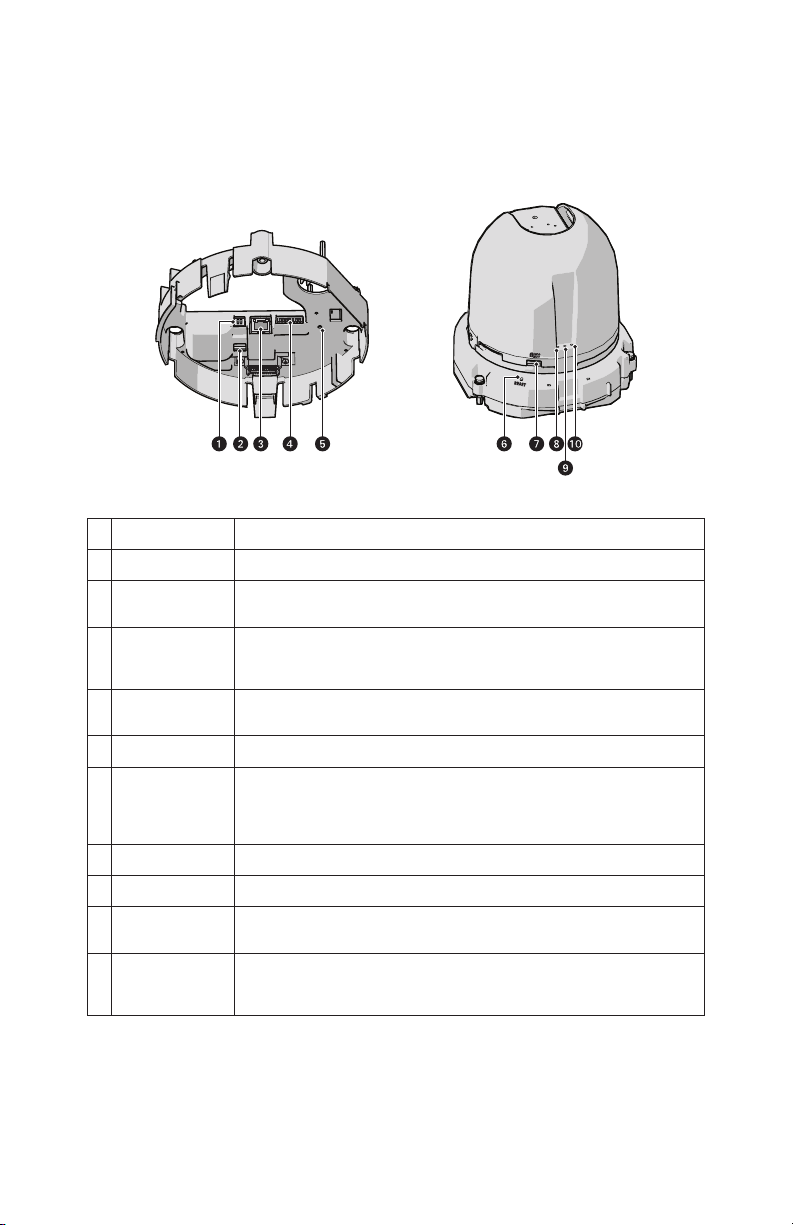
Figure 1: Connections and Features
# Connection/Feature Description
1 24 VAC Power Supplies power to the camera, and operates heater and blower in environmental units.
2 PoE+/HPoE Switch Switch to choose between PoE+ and HPoE. Must be set to the correct position based on what
3 RJ-45 Network Port Connects the camera to the IP network and supplies power to the camera through the network
4 Alarm, Relay, and
Audio In/Out
5 Power LED This LED glows solid green when the power is on. The LED is off when there is no power.
6 Reset Button Reboots the camera or restores the camera’s factory default settings. This button is recessed.
7 Micro SD Card Slot Slot for a removable Micro SD Card for flash memory.
8 Status LED Boots up red and turns off when video is available.
9 Debug LED This is a dual LED. It blinks green while the camera boots up and stays blinking. Before this, the
10Ethernet Link/Activity
LED
type of PoE injector is used.
using Power over Ethernet (PoE+ or HPoE). PoE+ will also operate blower in environmental units.
HPoE will also operate heater and blower in environmental units.
An 8-pin connector with one alarm, one relay, and audio in and out.
Using a small tool, such as a paper clip, press and release the reset button once to reboot the
camera. Press and hold the rest button for 10 seconds to restore the camera to the factory default
settings.
LED appears yellow.
This is a dual LED. The yellow LED indicates that a live network connection is established. The
green LED indicates that data is being transmitted or received by the camera. A blinking yellow
LED indicates a network link and network activities.
7

Installation Methods
You can install the Spectra Enhanced Series dome system using one of the following methods:
• Installation in a suspended ceiling or a fixed ceiling.
• Installation using a pendant mount (not supplied).
Installing the Back Box (In-Ceiling)
1. Locate the center point of the mounting location.
2. Insert the compass tool into the ceiling and draw a circle.
3. Cut out the circle.
4. Attach a conduit fitting (not supplied) and lock nut (not supplied).
5. Install a safety chain/cable (not supplied). The safety chain/cable should be capable of supporting up to 7.3 kg (16 lb).
6. Pull the wiring into the back box through the conduit fitting.
7. Install the back box:
a. Compress the spring clips and push the back box through the hole.
b. Tighten the screws until you hear a clicking noise.
Figure 1: Installing the Back Box: In-Ceiling Models
8. Connect the power wiring. Refer to the figure below and the Wiring topic for more information.
Figure 2: Power Wiring Connections: In-Ceiling Models
8

RA
Figure 3: Alarm/Relay/Audio Connector
# Connection/Feature Description
1 24 VAC Power Supplies power to the camera, and operates heater and blower in environmental units.
2 PoE+/HPoE Switch Switch to choose between PoE+ and HPoE. Must be set to the correct position based on the type of PoE
3 RJ-45 Network Port Connects the camera to the IP network and supplies power to the camera through the network using
4 Alarm, Relay, and Audio
In/Out
injector used.
Power over Ethernet (PoE+ or HPoE). PoE+ will also operate blower in environmental units. HPoE will
also operate heater and blower in environmental units.
An 8-pin connector with one alarm, one relay, and audio in and out.
5 Power LED This LED glows solid green when the power is on. The LED is off when there is no power.
9. FCC Class A installations: Attach the ferrite (supplied) to the network cable. Attach the ferrite on the cable as close as possible to
the camera’s RJ-45 network port.
WARNING: The ferrite must be installed for the camera to meet FCC Class A compliance standards. Failure to correctly install the
ferrite can cause harmful interference to radio communications.
Figure 4: Installing the Ferrite: In-Ceiling Models
Installing the Back Box (Pendant)
1. Install the pendant mount (not supplied). Refer to the instructions supplied with the mount.
2. Pull the wiring into the back box.
9

3. Screw the back box onto the pendant mount and apply thread compound (supplied) to the threads on the back box.
NOTE: Thread compound must be applied on both standard and environmental pendants. Not doing so may prevent the units from
being separated in the future.
4. Connect the power wiring. Refer to the figure below and the Wiring section for more information.
Figure 5: Power Wiring Connections: Pendant Models
RA
Figure 6: Alarm/Relay/Audio Connector
# Connection/Feature Description
1 24 VAC Power Supplies power to the camera, and operates heater and blower in environmental units.
2 PoE+/HPoE Switch Switch to choose between PoE+ and HPoE. Must be set to the correct position based on
3 RJ-45 Network Port Connects the camera to the IP network and supplies power to the camera through the
4 Alarm, Relay, and
Audio In/Out
the type of PoE injector used.
network using Power over Ethernet (PoE+ or HPoE). PoE+ will also operate blower in
environmental units. HPoE will also operate heater and blower in environmental units.
An 8-pin connector with one alarm, one relay, and audio in and out.
5 Power LED This LED glows solid green when the power is on. The LED is off when there is no power.
10
5. FCC Class A installations: Attach the ferrite (supplied) to the network cable. Attach the ferrite on the cable as close as possible to
the camera’s RJ-45 network port.
The ferrite must be installed for the camera to meet FCC Class A compliance standards. Failure to correctly install the ferrite can
cause harmful interference to radio communications.
Figure 7: Installing the Ferrite: Pendant Models
Installing the Dome Drive (In-Ceiling)
1. Line up the green and red markings on the dome drive with the green and red arrows inside the back box.
2. Push the in-ceiling dome drive into the clips until both sides click into place. The clips temporarily hold the dome drive into place.
3. Place one hand on or under the dome until the fasteners are secure.
4. Screw in the three captive fasteners until they are secure.
Figure 8: Installing the Dome Drive: In-Ceiling Models
Installing the Dome Drive (Pendant)
1. Line up the green and red markings on the pendant dome drive with the green and red arrows inside the back box.
2. Push the pendant dome drive into the clips until both sides click into place. The clips temporarily hold the dome drive in place.
3. Place one hand on or under the dome until the fasteners are secure.
11

4. Screw in the three captive fasteners until they are secure.
Figure 9: Installing the Dome Drive: Pendant Models
Installing the Lower Dome (In-Ceiling/Indoor)
1. Snap the clip on the end of the trim ring leash into the hole on the lip of the back box.
2. Snap the trim ring onto the plastic snap washers on the back box mounting screws.
Figure 10: Installing the Lower Dome: In-Ceiling Indoor Models
3. Apply power to the dome. The dome system will complete a configuration sequence
Installing the Lower Dome (In-Ceiling/Environmental)
1. Attach the back box leash to the lower dome.
2. Align the back box screws with the slots on the lower dome.
3. Push the lower dome onto the back box.
12

4. Tighten the screws to secure the lower dome to the back box.
Figure 11: Installing the Lower Dome: In-Ceiling Environmental Models
5. Apply power to the dome. The dome system will complete a configuration sequence.
Installing the Lower Dome (Indoor/Environmental/Pendant)
1. Attach the back box leash to the lower dome.
2. Align the back box screws with the slots on the lower dome.
3. Push the lower dome onto the back box.
4. Tighten the screws to secure the lower dome to the back box.
Figure 12: Installing the Lower Dome: Pendant Models
5. Apply power to the dome. The dome system will complete a configuration sequence.
13

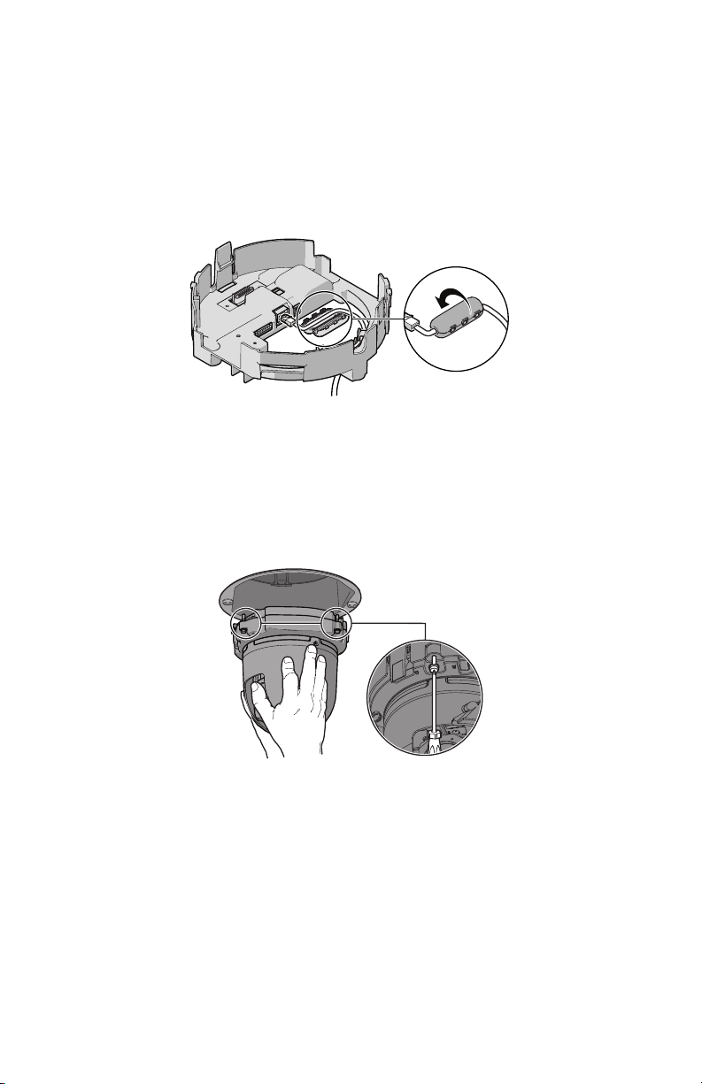
Installing the Lower Dome (Stainless Steel/Environmental/Pendant)
1. Attach the back box leash to the lower dome using the nearest retainer screw.
Figure 13: Attaching the Leash to the Stainless Steel Lower Dome
1 Leash
2 Retainer Screw
2. Lightly apply O-ring lubricant (supplied with the lower dome) to the O-ring, and then install the O-ring in the groove on the trim ring
of the lower dome.
3. Remove the two lower dome mounting screws, and apply a drop of Loctite® 222MS (supplied with lower dome) to each screw.
14

4. Push the lower dome into the back box, line upalign the mounting screw holes, and install the two mounting screws.
Figure 14: Installing the Stainless Steel Lower Dome
5. Apply power to the dome. The dome system will complete a configuration sequence.
15

Ethernet Wiring Requirement for POE+ and HPOE
1
2
3
4
5
6
7
8
8
8
1
A Cat5 cable or higher cable (not supplied) is used to connect the RJ-45 network port during the back box installation process. The 8-pin
port includes video through Ethernet, and PoE (PoE+ and HPoE) for the camera. PoE injects power over the same cabling that carries the
network data, eliminating the need for a separate power supply. This simplifies the installation and operation of the camera without
affecting network performance.
NOTE: Heater will be disabled when PoE+ is in use.
Refer to the figure below for pin descriptions.
8
1
7
6
5
4
3
2
1
Figure 1: Cable Pin Descriptions
Table A: Ethernet with POE+ Mode A
Pin Function
1 TX+, PoE 1-2
2 TX–, PoE 1-2
3 RX+, PoE 3-4
4 Not used
5 Not used
6 RX–, PoE 3-4
7 Not used
8 Not used
Table B: Ethernet with PoE+ Mode B (Sheet 1 of 2)
Pin Function
1TX+
2TX–
3RX+
4 PoE 1-2
5 PoE 1-2
16

Table B: Ethernet with PoE+ Mode B (Continued) (Sheet 2 of 2)
Pin Function
6RX
7 PoE 3-4
8 PoE 3-4
Table C: High Power PoE
Pin Function
1 TX+/PoE–
2 TX–/PoE–
3 RX+/PoE+
4 PoE+
5 PoE+
6 RX–/PoE+
7 PoE–
8 PoE–
17

24 VAC Wiring Distances
Power consumption for the environmental version is 82 VA. Use a 24 VAC transformer with a minimum of 100 VA per dome.
Table A: 24 VAC Wiring Distances
Wire Gauge
AC/DC Total VA
23 VA 38 m (123 ft) 60 m (196 ft) 95 m (311 ft) 151 m (495 ft)
82 VA 11 m (36 ft) 17 m (56 ft) 27 m (89 ft) 43 m (141 ft)
NOTE: Wire distances are based on normal condition estimates. The actual voltage drop can vary depending on the condition of the wire,
conductor being used, temperature, and connections.
20 AWG (0.5 mm2) 18 AWG (1.0 mm2) 16 AWG (1.5 mm2) 14 AWG (2.5 mm2)
Camera Configuration Sequence
Once the camera is installed and power is applied, the camera undergoes a configuration sequence, taking approximately two minutes
to complete. The camera will come online once the configuration sequence is complete.
NOTE: If the camera connected to a network without a DHCP server and DHCP is enabled, the configuration sequence can take up to five
minutes to complete.
18

Accessing the Camera
By default, users do not have to log in to view video; anyone who accesses the camera can view live video. If you want to prevent users
from viewing video without logging in, you must change the permissions for public users.
The recommended browsers for your camera are Internet Explorer
and Firefox for Mac
®
operating systems.
1. Open a web browser.
2. Type the camera’s IP address (192.168.0.20) or host name in your browser’s address bar, and then press Enter.
NOTE: You can obtain your camera’s IP address or access the camera using the Pelco Device Utility software. If DHCP is enabled
but a DHCP server is not on the network, the camera automatically assigns itself both an IPv4 link local address (169.254.x.x, where
the lower two octets are random) and a 192.168.0.20 address. Additional cameras will assign themselves different IPv4 link local
addresses and the next available 192.168.0.x IP addresses in sequential order. For example, if three cameras are connected to a
network without a DHCP server, the first camera to connect assigns itself the IP address 192.168.0.20, the second camera assigns
itself 192.168.0.21, and the third camera assigns itself 192.168.0.22.
3. Click Login.
4. Type your user name and password.
NOTE:
• In its out-of-the-box configuration, the camera has no user name and password assigned. For security purposes, it is recom-
mended that you set an administrative user name and password after initial configuration of the camera. Creation of an administrative user name changes the state of the camera to its “operational mode,” where credentials must be provided in order
to change its configuration.
• There is no provision for recovering a forgotten administrator user name or password. The camera can be restored to its
out-of-the box, no-password configuration by powering down, depressing the reset button with an object such as a paper clip,
and holding the button down for at least five seconds while powering the camera back up.
• If a user name and password exist, a Login link appears in the upper right area of your web browser.
5. Click Log In.
®
or Mozilla® Firefox® for Microsoft® Windows® operating systems
19

Pelco by Schneider Electric
3500 Pelco Way Clovis, California 93612 USA
(800) 289-9100 Tel (800) 289-9150 Fax
+1 (559) 292-1981 International Tel
+1 (559) 348-1120 International Fax
www.pelco.com
Pelco, the Pelco logo, and other trademarks associated with Pelco products referred to in this publication are trademarks of Pelco, Inc. or its affiliates. © Copyright 2015, Pelco, Inc.
ONVIF and the ONVIF logo are trademarks of ONVIF Inc. All other product names and services are the property of their respective companies. All rights reserved.
Product specifications and availability are subject to change without notice.
 Loading...