

INSTALLATION/OPERATION
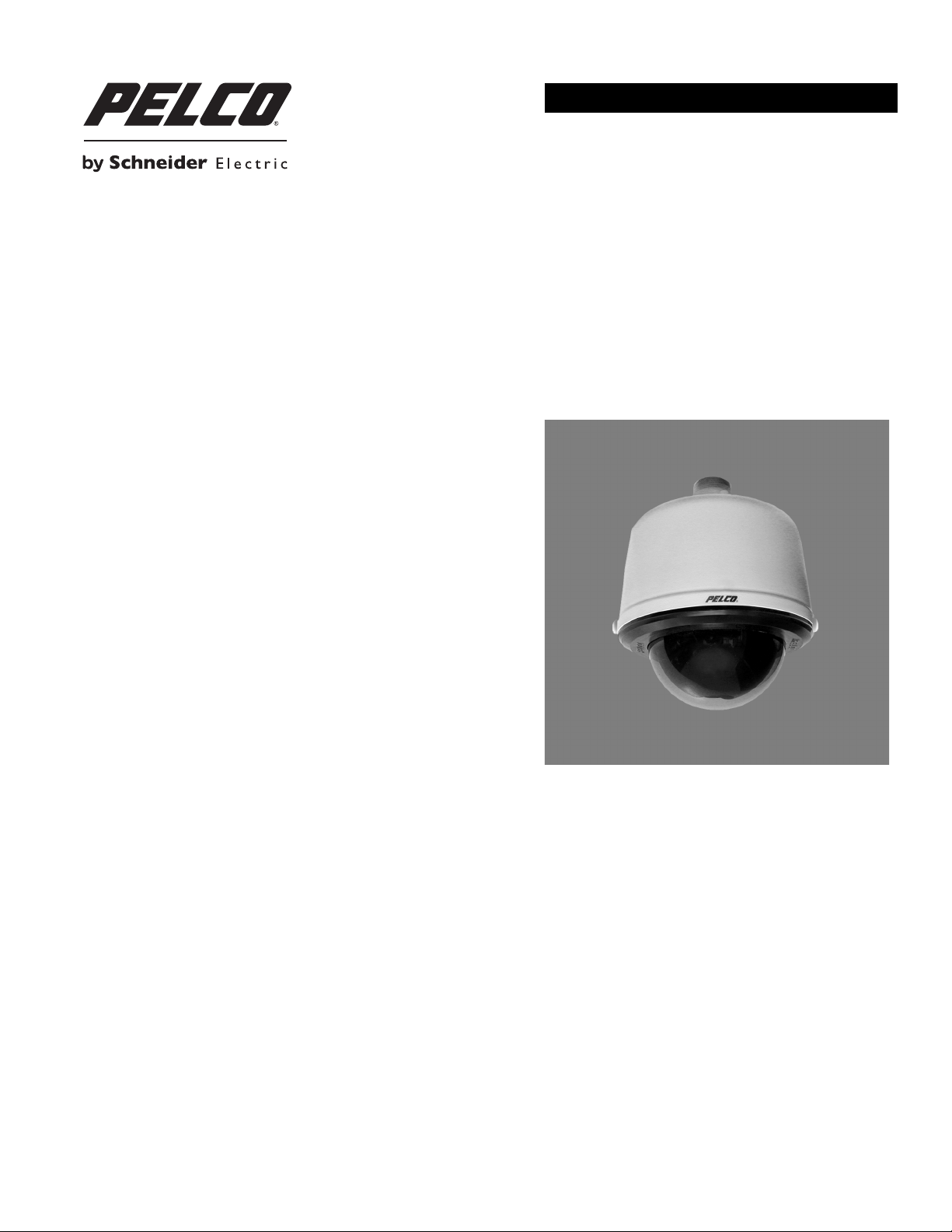
Spectra® HD Series Network Dome System
S5220 Models with Sarix™ Technology
C2267M (11/12)

Contents
Important Notices . . . . . . . . . . . . . . . . . . . . . . . . . . . . . . . . . . . . . . . . . . . . . . . . . . . . . . . . . . . . . . . . . . . . . . . . . . . . . . . . . . . . . . . . . . . . . . . . . . . . . 7
Legal Notice . . . . . . . . . . . . . . . . . . . . . . . . . . . . . . . . . . . . . . . . . . . . . . . . . . . . . . . . . . . . . . . . . . . . . . . . . . . . . . . . . . . . . . . . . . . . . . . . . . . . . 7
Regulatory Notices . . . . . . . . . . . . . . . . . . . . . . . . . . . . . . . . . . . . . . . . . . . . . . . . . . . . . . . . . . . . . . . . . . . . . . . . . . . . . . . . . . . . . . . . . . . . . . . . 7
Video Quality Caution . . . . . . . . . . . . . . . . . . . . . . . . . . . . . . . . . . . . . . . . . . . . . . . . . . . . . . . . . . . . . . . . . . . . . . . . . . . . . . . . . . . . . . . . . . . . . . 7
Open Source Software Notice . . . . . . . . . . . . . . . . . . . . . . . . . . . . . . . . . . . . . . . . . . . . . . . . . . . . . . . . . . . . . . . . . . . . . . . . . . . . . . . . . . . . . . .7
Introduction . . . . . . . . . . . . . . . . . . . . . . . . . . . . . . . . . . . . . . . . . . . . . . . . . . . . . . . . . . . . . . . . . . . . . . . . . . . . . . . . . . . . . . . . . . . . . . . . . . . . . . . . . . 8
Compatible Systems . . . . . . . . . . . . . . . . . . . . . . . . . . . . . . . . . . . . . . . . . . . . . . . . . . . . . . . . . . . . . . . . . . . . . . . . . . . . . . . . . . . . . . . . . . . . . . . 8
Models . . . . . . . . . . . . . . . . . . . . . . . . . . . . . . . . . . . . . . . . . . . . . . . . . . . . . . . . . . . . . . . . . . . . . . . . . . . . . . . . . . . . . . . . . . . . . . . . . . . . . . . . .8
Getting Started . . . . . . . . . . . . . . . . . . . . . . . . . . . . . . . . . . . . . . . . . . . . . . . . . . . . . . . . . . . . . . . . . . . . . . . . . . . . . . . . . . . . . . . . . . . . . . . . . . . . . . . 8
Parts List . . . . . . . . . . . . . . . . . . . . . . . . . . . . . . . . . . . . . . . . . . . . . . . . . . . . . . . . . . . . . . . . . . . . . . . . . . . . . . . . . . . . . . . . . . . . . . . . . . . . . . . . 9
Product Overview. . . . . . . . . . . . . . . . . . . . . . . . . . . . . . . . . . . . . . . . . . . . . . . . . . . . . . . . . . . . . . . . . . . . . . . . . . . . . . . . . . . . . . . . . . . . . . . . . . . . . 10
Installation . . . . . . . . . . . . . . . . . . . . . . . . . . . . . . . . . . . . . . . . . . . . . . . . . . . . . . . . . . . . . . . . . . . . . . . . . . . . . . . . . . . . . . . . . . . . . . . . . . . . . . . . . . 11
In-Ceiling Models . . . . . . . . . . . . . . . . . . . . . . . . . . . . . . . . . . . . . . . . . . . . . . . . . . . . . . . . . . . . . . . . . . . . . . . . . . . . . . . . . . . . . . . . . . . . . . . .11
Pendant Models . . . . . . . . . . . . . . . . . . . . . . . . . . . . . . . . . . . . . . . . . . . . . . . . . . . . . . . . . . . . . . . . . . . . . . . . . . . . . . . . . . . . . . . . . . . . . . . . . 15
Wiring . . . . . . . . . . . . . . . . . . . . . . . . . . . . . . . . . . . . . . . . . . . . . . . . . . . . . . . . . . . . . . . . . . . . . . . . . . . . . . . . . . . . . . . . . . . . . . . . . . . . . . . . . 17
Operation . . . . . . . . . . . . . . . . . . . . . . . . . . . . . . . . . . . . . . . . . . . . . . . . . . . . . . . . . . . . . . . . . . . . . . . . . . . . . . . . . . . . . . . . . . . . . . . . . . . . . . . . . . . 18
Camera Configuration Sequence . . . . . . . . . . . . . . . . . . . . . . . . . . . . . . . . . . . . . . . . . . . . . . . . . . . . . . . . . . . . . . . . . . . . . . . . . . . . . . . . . . . . 18
Minimum System Requirements . . . . . . . . . . . . . . . . . . . . . . . . . . . . . . . . . . . . . . . . . . . . . . . . . . . . . . . . . . . . . . . . . . . . . . . . . . . . . . . . . . . . 18
Accessing the IP Camera . . . . . . . . . . . . . . . . . . . . . . . . . . . . . . . . . . . . . . . . . . . . . . . . . . . . . . . . . . . . . . . . . . . . . . . . . . . . . . . . . . . . . . . . . . 19
In-Ceiling Models. . . . . . . . . . . . . . . . . . . . . . . . . . . . . . . . . . . . . . . . . . . . . . . . . . . . . . . . . . . . . . . . . . . . . . . . . . . . . . . . . . . . . . . . . . . . . 9
Pendant Models. . . . . . . . . . . . . . . . . . . . . . . . . . . . . . . . . . . . . . . . . . . . . . . . . . . . . . . . . . . . . . . . . . . . . . . . . . . . . . . . . . . . . . . . . . . . . . 9
Cat5 Requirement for PoE . . . . . . . . . . . . . . . . . . . . . . . . . . . . . . . . . . . . . . . . . . . . . . . . . . . . . . . . . . . . . . . . . . . . . . . . . . . . . . . . . . . . . 17
24 VAC . . . . . . . . . . . . . . . . . . . . . . . . . . . . . . . . . . . . . . . . . . . . . . . . . . . . . . . . . . . . . . . . . . . . . . . . . . . . . . . . . . . . . . . . . . . . . . . . . . . . 17
Logging On to the Camera . . . . . . . . . . . . . . . . . . . . . . . . . . . . . . . . . . . . . . . . . . . . . . . . . . . . . . . . . . . . . . . . . . . . . . . . . . . . . . . . . . . . . 19
Live Video Page . . . . . . . . . . . . . . . . . . . . . . . . . . . . . . . . . . . . . . . . . . . . . . . . . . . . . . . . . . . . . . . . . . . . . . . . . . . . . . . . . . . . . . . . . . . . . . . . . . . . . . 20
Live Video Page Icons . . . . . . . . . . . . . . . . . . . . . . . . . . . . . . . . . . . . . . . . . . . . . . . . . . . . . . . . . . . . . . . . . . . . . . . . . . . . . . . . . . . . . . . . . . . . . 20
PTZ Controls . . . . . . . . . . . . . . . . . . . . . . . . . . . . . . . . . . . . . . . . . . . . . . . . . . . . . . . . . . . . . . . . . . . . . . . . . . . . . . . . . . . . . . . . . . . . . . . . . . . . 21
Keyboard Shortcuts. . . . . . . . . . . . . . . . . . . . . . . . . . . . . . . . . . . . . . . . . . . . . . . . . . . . . . . . . . . . . . . . . . . . . . . . . . . . . . . . . . . . . . . . . . . . . . .21
Selecting a Stream . . . . . . . . . . . . . . . . . . . . . . . . . . . . . . . . . . . . . . . . . . . . . . . . . . . . . . . . . . . . . . . . . . . . . . . . . . . . . . . . . . . . . . . . . . . . . . . 22
Primary Stream and Secondary Stream. . . . . . . . . . . . . . . . . . . . . . . . . . . . . . . . . . . . . . . . . . . . . . . . . . . . . . . . . . . . . . . . . . . . . . . . . . . 22
QuickView Stream . . . . . . . . . . . . . . . . . . . . . . . . . . . . . . . . . . . . . . . . . . . . . . . . . . . . . . . . . . . . . . . . . . . . . . . . . . . . . . . . . . . . . . . . . . . 22
Event Stream . . . . . . . . . . . . . . . . . . . . . . . . . . . . . . . . . . . . . . . . . . . . . . . . . . . . . . . . . . . . . . . . . . . . . . . . . . . . . . . . . . . . . . . . . . . . . . .22
Unicast . . . . . . . . . . . . . . . . . . . . . . . . . . . . . . . . . . . . . . . . . . . . . . . . . . . . . . . . . . . . . . . . . . . . . . . . . . . . . . . . . . . . . . . . . . . . . . . . . . . . 23
Multicast . . . . . . . . . . . . . . . . . . . . . . . . . . . . . . . . . . . . . . . . . . . . . . . . . . . . . . . . . . . . . . . . . . . . . . . . . . . . . . . . . . . . . . . . . . . . . . . . . . 23
Throttle. . . . . . . . . . . . . . . . . . . . . . . . . . . . . . . . . . . . . . . . . . . . . . . . . . . . . . . . . . . . . . . . . . . . . . . . . . . . . . . . . . . . . . . . . . . . . . . . . . . .23
Taking a Snapshot . . . . . . . . . . . . . . . . . . . . . . . . . . . . . . . . . . . . . . . . . . . . . . . . . . . . . . . . . . . . . . . . . . . . . . . . . . . . . . . . . . . . . . . . . . . . . . . 23
Settings Page. . . . . . . . . . . . . . . . . . . . . . . . . . . . . . . . . . . . . . . . . . . . . . . . . . . . . . . . . . . . . . . . . . . . . . . . . . . . . . . . . . . . . . . . . . . . . . . . . . . . . . . . 24
Accessing the Camera Menus . . . . . . . . . . . . . . . . . . . . . . . . . . . . . . . . . . . . . . . . . . . . . . . . . . . . . . . . . . . . . . . . . . . . . . . . . . . . . . . . . . . . . .24
System Tab . . . . . . . . . . . . . . . . . . . . . . . . . . . . . . . . . . . . . . . . . . . . . . . . . . . . . . . . . . . . . . . . . . . . . . . . . . . . . . . . . . . . . . . . . . . . . . . . . . . . . . . . . 25
Changing the Device Name . . . . . . . . . . . . . . . . . . . . . . . . . . . . . . . . . . . . . . . . . . . . . . . . . . . . . . . . . . . . . . . . . . . . . . . . . . . . . . . . . . . . . . . . 25
Enabling LEDs . . . . . . . . . . . . . . . . . . . . . . . . . . . . . . . . . . . . . . . . . . . . . . . . . . . . . . . . . . . . . . . . . . . . . . . . . . . . . . . . . . . . . . . . . . . . . . . . . . . 26
Configuring the SMTP Server . . . . . . . . . . . . . . . . . . . . . . . . . . . . . . . . . . . . . . . . . . . . . . . . . . . . . . . . . . . . . . . . . . . . . . . . . . . . . . . . . . . . . . .26
Configuring DHCP Time Server Settings . . . . . . . . . . . . . . . . . . . . . . . . . . . . . . . . . . . . . . . . . . . . . . . . . . . . . . . . . . . . . . . . . . . . . . . . . . . . . . 26
Configuring Manual Time Server Settings. . . . . . . . . . . . . . . . . . . . . . . . . . . . . . . . . . . . . . . . . . . . . . . . . . . . . . . . . . . . . . . . . . . . . . . . . . . . . 26
Customizing the Appearance of the Text Overlay . . . . . . . . . . . . . . . . . . . . . . . . . . . . . . . . . . . . . . . . . . . . . . . . . . . . . . . . . . . . . . . . . . . . . . . 27
Generating a System Log . . . . . . . . . . . . . . . . . . . . . . . . . . . . . . . . . . . . . . . . . . . . . . . . . . . . . . . . . . . . . . . . . . . . . . . . . . . . . . . . . . . . . . . . . .27
Rebooting the Camera . . . . . . . . . . . . . . . . . . . . . . . . . . . . . . . . . . . . . . . . . . . . . . . . . . . . . . . . . . . . . . . . . . . . . . . . . . . . . . . . . . . . . . . . . . . . 27
Restoring All Camera Defaults . . . . . . . . . . . . . . . . . . . . . . . . . . . . . . . . . . . . . . . . . . . . . . . . . . . . . . . . . . . . . . . . . . . . . . . . . . . . . . . . . . . . . .27
Downloading a Full Backup of Camera Settings . . . . . . . . . . . . . . . . . . . . . . . . . . . . . . . . . . . . . . . . . . . . . . . . . . . . . . . . . . . . . . . . . . . . . . . . 28
Uploading a Backup File to Restore Camera Settings . . . . . . . . . . . . . . . . . . . . . . . . . . . . . . . . . . . . . . . . . . . . . . . . . . . . . . . . . . . . . . . . . . . . 28
C2267M (11/12) 3

Network Tab . . . . . . . . . . . . . . . . . . . . . . . . . . . . . . . . . . . . . . . . . . . . . . . . . . . . . . . . . . . . . . . . . . . . . . . . . . . . . . . . . . . . . . . . . . . . . . . . . . . . . . . . 29
Changing the Host Name . . . . . . . . . . . . . . . . . . . . . . . . . . . . . . . . . . . . . . . . . . . . . . . . . . . . . . . . . . . . . . . . . . . . . . . . . . . . . . . . . . . . . . . . . . 30
Configuring the HTTP Port . . . . . . . . . . . . . . . . . . . . . . . . . . . . . . . . . . . . . . . . . . . . . . . . . . . . . . . . . . . . . . . . . . . . . . . . . . . . . . . . . . . . . . . . . 30
Configuring the HTTPS Port . . . . . . . . . . . . . . . . . . . . . . . . . . . . . . . . . . . . . . . . . . . . . . . . . . . . . . . . . . . . . . . . . . . . . . . . . . . . . . . . . . . . . . . .30
Configuring the RTSP Port . . . . . . . . . . . . . . . . . . . . . . . . . . . . . . . . . . . . . . . . . . . . . . . . . . . . . . . . . . . . . . . . . . . . . . . . . . . . . . . . . . . . . . . . . 30
Turning On DHCP . . . . . . . . . . . . . . . . . . . . . . . . . . . . . . . . . . . . . . . . . . . . . . . . . . . . . . . . . . . . . . . . . . . . . . . . . . . . . . . . . . . . . . . . . . . . . . . . 31
Turning Off DHCP . . . . . . . . . . . . . . . . . . . . . . . . . . . . . . . . . . . . . . . . . . . . . . . . . . . . . . . . . . . . . . . . . . . . . . . . . . . . . . . . . . . . . . . . . . . . . . . . 31
Selecting the Secure Sockets Layer Mode. . . . . . . . . . . . . . . . . . . . . . . . . . . . . . . . . . . . . . . . . . . . . . . . . . . . . . . . . . . . . . . . . . . . . . . . . . . . . 32
Generating a Self-Signed Certificate . . . . . . . . . . . . . . . . . . . . . . . . . . . . . . . . . . . . . . . . . . . . . . . . . . . . . . . . . . . . . . . . . . . . . . . . . . . .32
Deleting a Self-Signed Certificate. . . . . . . . . . . . . . . . . . . . . . . . . . . . . . . . . . . . . . . . . . . . . . . . . . . . . . . . . . . . . . . . . . . . . . . . . . . . . . . 32
Generating a Certificate Request . . . . . . . . . . . . . . . . . . . . . . . . . . . . . . . . . . . . . . . . . . . . . . . . . . . . . . . . . . . . . . . . . . . . . . . . . . . . . . . 33
Enabling Secure Shell . . . . . . . . . . . . . . . . . . . . . . . . . . . . . . . . . . . . . . . . . . . . . . . . . . . . . . . . . . . . . . . . . . . . . . . . . . . . . . . . . . . . . . . . . . . . . 33
Configuring the 802.1x Port Security Settings . . . . . . . . . . . . . . . . . . . . . . . . . . . . . . . . . . . . . . . . . . . . . . . . . . . . . . . . . . . . . . . . . . . . . . . . . . 33
Selecting SNMP Settings . . . . . . . . . . . . . . . . . . . . . . . . . . . . . . . . . . . . . . . . . . . . . . . . . . . . . . . . . . . . . . . . . . . . . . . . . . . . . . . . . . . . . . . . . . 34
Configuring SNMP V2c . . . . . . . . . . . . . . . . . . . . . . . . . . . . . . . . . . . . . . . . . . . . . . . . . . . . . . . . . . . . . . . . . . . . . . . . . . . . . . . . . . . . . . .34
Configuring SNMP V3 . . . . . . . . . . . . . . . . . . . . . . . . . . . . . . . . . . . . . . . . . . . . . . . . . . . . . . . . . . . . . . . . . . . . . . . . . . . . . . . . . . . . . . . . 34
Imaging Tab . . . . . . . . . . . . . . . . . . . . . . . . . . . . . . . . . . . . . . . . . . . . . . . . . . . . . . . . . . . . . . . . . . . . . . . . . . . . . . . . . . . . . . . . . . . . . . . . . . . . . . . . . 35
Changing Freeze Frame Settings . . . . . . . . . . . . . . . . . . . . . . . . . . . . . . . . . . . . . . . . . . . . . . . . . . . . . . . . . . . . . . . . . . . . . . . . . . . . . . . . . . . . 36
Enabling Digital Zoom. . . . . . . . . . . . . . . . . . . . . . . . . . . . . . . . . . . . . . . . . . . . . . . . . . . . . . . . . . . . . . . . . . . . . . . . . . . . . . . . . . . . . . . . . . . . .37
Changing the Focus Settings . . . . . . . . . . . . . . . . . . . . . . . . . . . . . . . . . . . . . . . . . . . . . . . . . . . . . . . . . . . . . . . . . . . . . . . . . . . . . . . . . . . . . . . 37
Changing the Digital Processing Settings . . . . . . . . . . . . . . . . . . . . . . . . . . . . . . . . . . . . . . . . . . . . . . . . . . . . . . . . . . . . . . . . . . . . . . . . . . . . . 38
Selecting Normal Exposure Settings . . . . . . . . . . . . . . . . . . . . . . . . . . . . . . . . . . . . . . . . . . . . . . . . . . . . . . . . . . . . . . . . . . . . . . . . . . . . . . . . .38
Selecting Exposure Time and Gain Control Settings . . . . . . . . . . . . . . . . . . . . . . . . . . . . . . . . . . . . . . . . . . . . . . . . . . . . . . . . . . . . . . . . . . . . .39
Day Night Settings . . . . . . . . . . . . . . . . . . . . . . . . . . . . . . . . . . . . . . . . . . . . . . . . . . . . . . . . . . . . . . . . . . . . . . . . . . . . . . . . . . . . . . . . . . . . . . . 39
Selecting Day Night Auto Mode . . . . . . . . . . . . . . . . . . . . . . . . . . . . . . . . . . . . . . . . . . . . . . . . . . . . . . . . . . . . . . . . . . . . . . . . . . . . . . . .39
Selecting Day Night Manual Mode . . . . . . . . . . . . . . . . . . . . . . . . . . . . . . . . . . . . . . . . . . . . . . . . . . . . . . . . . . . . . . . . . . . . . . . . . . . . . . 39
Selecting Backlight Compensation. . . . . . . . . . . . . . . . . . . . . . . . . . . . . . . . . . . . . . . . . . . . . . . . . . . . . . . . . . . . . . . . . . . . . . . . . . . . . . . . . . .40
Selecting Wide Dynamic Range Processing. . . . . . . . . . . . . . . . . . . . . . . . . . . . . . . . . . . . . . . . . . . . . . . . . . . . . . . . . . . . . . . . . . . . . . . . . . . . 40
Selecting the White Balance Mode . . . . . . . . . . . . . . . . . . . . . . . . . . . . . . . . . . . . . . . . . . . . . . . . . . . . . . . . . . . . . . . . . . . . . . . . . . . . . . . . . . 40
Turning On Window Blanking. . . . . . . . . . . . . . . . . . . . . . . . . . . . . . . . . . . . . . . . . . . . . . . . . . . . . . . . . . . . . . . . . . . . . . . . . . . . . . . . . . . . . . . 41
Turning Off Window Blanking . . . . . . . . . . . . . . . . . . . . . . . . . . . . . . . . . . . . . . . . . . . . . . . . . . . . . . . . . . . . . . . . . . . . . . . . . . . . . . . . . . . . . . 41
Deleting a Window Blanking Area . . . . . . . . . . . . . . . . . . . . . . . . . . . . . . . . . . . . . . . . . . . . . . . . . . . . . . . . . . . . . . . . . . . . . . . . . . . . . . . . . . .41
Restoring Window Blanking Defaults . . . . . . . . . . . . . . . . . . . . . . . . . . . . . . . . . . . . . . . . . . . . . . . . . . . . . . . . . . . . . . . . . . . . . . . . . . . . . . . . 41
Creating a Preset . . . . . . . . . . . . . . . . . . . . . . . . . . . . . . . . . . . . . . . . . . . . . . . . . . . . . . . . . . . . . . . . . . . . . . . . . . . . . . . . . . . . . . . . . . . . . . . . 42
Deleting a Preset . . . . . . . . . . . . . . . . . . . . . . . . . . . . . . . . . . . . . . . . . . . . . . . . . . . . . . . . . . . . . . . . . . . . . . . . . . . . . . . . . . . . . . . . . . . . . . . . 42
Creating a Preset Tour . . . . . . . . . . . . . . . . . . . . . . . . . . . . . . . . . . . . . . . . . . . . . . . . . . . . . . . . . . . . . . . . . . . . . . . . . . . . . . . . . . . . . . . . . . . . 42
Deleting a Preset from a Tour. . . . . . . . . . . . . . . . . . . . . . . . . . . . . . . . . . . . . . . . . . . . . . . . . . . . . . . . . . . . . . . . . . . . . . . . . . . . . . . . . . . . . . . 43
Deleting a Preset Tour . . . . . . . . . . . . . . . . . . . . . . . . . . . . . . . . . . . . . . . . . . . . . . . . . . . . . . . . . . . . . . . . . . . . . . . . . . . . . . . . . . . . . . . . . . . . 43
Configuring Pan/Tilt Speed Control . . . . . . . . . . . . . . . . . . . . . . . . . . . . . . . . . . . . . . . . . . . . . . . . . . . . . . . . . . . . . . . . . . . . . . . . . . . . . . . . . . 43
Configuring the Pan Center Point (Azimuth Zero). . . . . . . . . . . . . . . . . . . . . . . . . . . . . . . . . . . . . . . . . . . . . . . . . . . . . . . . . . . . . . . . . . . . . . . . 43
Configuring the Pan Limit Stops . . . . . . . . . . . . . . . . . . . . . . . . . . . . . . . . . . . . . . . . . . . . . . . . . . . . . . . . . . . . . . . . . . . . . . . . . . . . . . . . . . . . .44
Configuring the Tilt Limit Stops . . . . . . . . . . . . . . . . . . . . . . . . . . . . . . . . . . . . . . . . . . . . . . . . . . . . . . . . . . . . . . . . . . . . . . . . . . . . . . . . . . . . . 44
A/V Streams Tab . . . . . . . . . . . . . . . . . . . . . . . . . . . . . . . . . . . . . . . . . . . . . . . . . . . . . . . . . . . . . . . . . . . . . . . . . . . . . . . . . . . . . . . . . . . . . . . . . . . . .45
Selecting a Video Preset Configuration . . . . . . . . . . . . . . . . . . . . . . . . . . . . . . . . . . . . . . . . . . . . . . . . . . . . . . . . . . . . . . . . . . . . . . . . . . . . . . .45
Configuring a Custom Video Stream Configuration . . . . . . . . . . . . . . . . . . . . . . . . . . . . . . . . . . . . . . . . . . . . . . . . . . . . . . . . . . . . . . . . . . . . . . 46
Compression Standards. . . . . . . . . . . . . . . . . . . . . . . . . . . . . . . . . . . . . . . . . . . . . . . . . . . . . . . . . . . . . . . . . . . . . . . . . . . . . . . . . . . . . . .46
Resolution . . . . . . . . . . . . . . . . . . . . . . . . . . . . . . . . . . . . . . . . . . . . . . . . . . . . . . . . . . . . . . . . . . . . . . . . . . . . . . . . . . . . . . . . . . . . . . . . . 46
Image Rate. . . . . . . . . . . . . . . . . . . . . . . . . . . . . . . . . . . . . . . . . . . . . . . . . . . . . . . . . . . . . . . . . . . . . . . . . . . . . . . . . . . . . . . . . . . . . . . . . 46
Bit Rate . . . . . . . . . . . . . . . . . . . . . . . . . . . . . . . . . . . . . . . . . . . . . . . . . . . . . . . . . . . . . . . . . . . . . . . . . . . . . . . . . . . . . . . . . . . . . . . . . . . 47
I-Frame Interval . . . . . . . . . . . . . . . . . . . . . . . . . . . . . . . . . . . . . . . . . . . . . . . . . . . . . . . . . . . . . . . . . . . . . . . . . . . . . . . . . . . . . . . . . . . . . 47
Quality of Service for Differentiated Services Code Point . . . . . . . . . . . . . . . . . . . . . . . . . . . . . . . . . . . . . . . . . . . . . . . . . . . . . . . . . . . . 47
Endura Signing. . . . . . . . . . . . . . . . . . . . . . . . . . . . . . . . . . . . . . . . . . . . . . . . . . . . . . . . . . . . . . . . . . . . . . . . . . . . . . . . . . . . . . . . . . . . . . 47
Profile. . . . . . . . . . . . . . . . . . . . . . . . . . . . . . . . . . . . . . . . . . . . . . . . . . . . . . . . . . . . . . . . . . . . . . . . . . . . . . . . . . . . . . . . . . . . . . . . . . . . . 47
GOP Structure . . . . . . . . . . . . . . . . . . . . . . . . . . . . . . . . . . . . . . . . . . . . . . . . . . . . . . . . . . . . . . . . . . . . . . . . . . . . . . . . . . . . . . . . . . . . . . 47
Selecting Audio Configuration Settings . . . . . . . . . . . . . . . . . . . . . . . . . . . . . . . . . . . . . . . . . . . . . . . . . . . . . . . . . . . . . . . . . . . . . . . . . . . . . . . 48
Users Tab . . . . . . . . . . . . . . . . . . . . . . . . . . . . . . . . . . . . . . . . . . . . . . . . . . . . . . . . . . . . . . . . . . . . . . . . . . . . . . . . . . . . . . . . . . . . . . . . . . . . . . . . . . .49
Selecting the Users and Groups Settings. . . . . . . . . . . . . . . . . . . . . . . . . . . . . . . . . . . . . . . . . . . . . . . . . . . . . . . . . . . . . . . . . . . . . . . . . . . . . .49
Enabling Remote Mode . . . . . . . . . . . . . . . . . . . . . . . . . . . . . . . . . . . . . . . . . . . . . . . . . . . . . . . . . . . . . . . . . . . . . . . . . . . . . . . . . . . . . . . . . . . 50
Creating a New User . . . . . . . . . . . . . . . . . . . . . . . . . . . . . . . . . . . . . . . . . . . . . . . . . . . . . . . . . . . . . . . . . . . . . . . . . . . . . . . . . . . . . . . . . . . . . 50
4 C2267M (11/12)

Editing a User . . . . . . . . . . . . . . . . . . . . . . . . . . . . . . . . . . . . . . . . . . . . . . . . . . . . . . . . . . . . . . . . . . . . . . . . . . . . . . . . . . . . . . . . . . . . . . . . . . .51
Deleting a User . . . . . . . . . . . . . . . . . . . . . . . . . . . . . . . . . . . . . . . . . . . . . . . . . . . . . . . . . . . . . . . . . . . . . . . . . . . . . . . . . . . . . . . . . . . . . . . . . . 51
Events Tab . . . . . . . . . . . . . . . . . . . . . . . . . . . . . . . . . . . . . . . . . . . . . . . . . . . . . . . . . . . . . . . . . . . . . . . . . . . . . . . . . . . . . . . . . . . . . . . . . . . . . . . . . . 52
Sources . . . . . . . . . . . . . . . . . . . . . . . . . . . . . . . . . . . . . . . . . . . . . . . . . . . . . . . . . . . . . . . . . . . . . . . . . . . . . . . . . . . . . . . . . . . . . . . . . . . . . . . . 53
Creating an Alarm Event Source . . . . . . . . . . . . . . . . . . . . . . . . . . . . . . . . . . . . . . . . . . . . . . . . . . . . . . . . . . . . . . . . . . . . . . . . . . . . . . . . 53
Creating an Analytic Event Source . . . . . . . . . . . . . . . . . . . . . . . . . . . . . . . . . . . . . . . . . . . . . . . . . . . . . . . . . . . . . . . . . . . . . . . . . . . . . . 54
Creating a Park Action Event Source. . . . . . . . . . . . . . . . . . . . . . . . . . . . . . . . . . . . . . . . . . . . . . . . . . . . . . . . . . . . . . . . . . . . . . . . . . . . . 54
Creating a System Event Source . . . . . . . . . . . . . . . . . . . . . . . . . . . . . . . . . . . . . . . . . . . . . . . . . . . . . . . . . . . . . . . . . . . . . . . . . . . . . . . . 54
Creating a Timer Event Source . . . . . . . . . . . . . . . . . . . . . . . . . . . . . . . . . . . . . . . . . . . . . . . . . . . . . . . . . . . . . . . . . . . . . . . . . . . . . . . . . 54
Editing an Event Source. . . . . . . . . . . . . . . . . . . . . . . . . . . . . . . . . . . . . . . . . . . . . . . . . . . . . . . . . . . . . . . . . . . . . . . . . . . . . . . . . . . . . . .55
Deleting an Event Source . . . . . . . . . . . . . . . . . . . . . . . . . . . . . . . . . . . . . . . . . . . . . . . . . . . . . . . . . . . . . . . . . . . . . . . . . . . . . . . . . . . . . 55
Handlers . . . . . . . . . . . . . . . . . . . . . . . . . . . . . . . . . . . . . . . . . . . . . . . . . . . . . . . . . . . . . . . . . . . . . . . . . . . . . . . . . . . . . . . . . . . . . . . . . . . . . . . 55
Creating an Event Handler: Send Email. . . . . . . . . . . . . . . . . . . . . . . . . . . . . . . . . . . . . . . . . . . . . . . . . . . . . . . . . . . . . . . . . . . . . . . . . . . 56
Creating an Event Handler: Upload JPEG to FTP Server. . . . . . . . . . . . . . . . . . . . . . . . . . . . . . . . . . . . . . . . . . . . . . . . . . . . . . . . . . . . . . 56
Creating an Event Handler: Go To Preset . . . . . . . . . . . . . . . . . . . . . . . . . . . . . . . . . . . . . . . . . . . . . . . . . . . . . . . . . . . . . . . . . . . . . . . . . 57
Creating an Event Handler: Open Close Relay . . . . . . . . . . . . . . . . . . . . . . . . . . . . . . . . . . . . . . . . . . . . . . . . . . . . . . . . . . . . . . . . . . . . .57
Creating an Event Handler: Run Tour . . . . . . . . . . . . . . . . . . . . . . . . . . . . . . . . . . . . . . . . . . . . . . . . . . . . . . . . . . . . . . . . . . . . . . . . . . . . 58
Editing an Event Handler . . . . . . . . . . . . . . . . . . . . . . . . . . . . . . . . . . . . . . . . . . . . . . . . . . . . . . . . . . . . . . . . . . . . . . . . . . . . . . . . . . . . . . 58
Deleting an Event Handler. . . . . . . . . . . . . . . . . . . . . . . . . . . . . . . . . . . . . . . . . . . . . . . . . . . . . . . . . . . . . . . . . . . . . . . . . . . . . . . . . . . . . 58
Example Handler Filter Setup . . . . . . . . . . . . . . . . . . . . . . . . . . . . . . . . . . . . . . . . . . . . . . . . . . . . . . . . . . . . . . . . . . . . . . . . . . . . . . . . . .58
Analytic Configuration . . . . . . . . . . . . . . . . . . . . . . . . . . . . . . . . . . . . . . . . . . . . . . . . . . . . . . . . . . . . . . . . . . . . . . . . . . . . . . . . . . . . . . . . . . . .59
Profiles . . . . . . . . . . . . . . . . . . . . . . . . . . . . . . . . . . . . . . . . . . . . . . . . . . . . . . . . . . . . . . . . . . . . . . . . . . . . . . . . . . . . . . . . . . . . . . . . . . . . 59
Behaviors . . . . . . . . . . . . . . . . . . . . . . . . . . . . . . . . . . . . . . . . . . . . . . . . . . . . . . . . . . . . . . . . . . . . . . . . . . . . . . . . . . . . . . . . . . . . . . . . . . 61
Zones . . . . . . . . . . . . . . . . . . . . . . . . . . . . . . . . . . . . . . . . . . . . . . . . . . . . . . . . . . . . . . . . . . . . . . . . . . . . . . . . . . . . . . . . . . . . . . . . . . . . .62
Abandoned Object . . . . . . . . . . . . . . . . . . . . . . . . . . . . . . . . . . . . . . . . . . . . . . . . . . . . . . . . . . . . . . . . . . . . . . . . . . . . . . . . . . . . . . . . . . . 63
Adaptive Motion . . . . . . . . . . . . . . . . . . . . . . . . . . . . . . . . . . . . . . . . . . . . . . . . . . . . . . . . . . . . . . . . . . . . . . . . . . . . . . . . . . . . . . . . . . . .64
AutoTracker . . . . . . . . . . . . . . . . . . . . . . . . . . . . . . . . . . . . . . . . . . . . . . . . . . . . . . . . . . . . . . . . . . . . . . . . . . . . . . . . . . . . . . . . . . . . . . . .65
Camera Sabotage . . . . . . . . . . . . . . . . . . . . . . . . . . . . . . . . . . . . . . . . . . . . . . . . . . . . . . . . . . . . . . . . . . . . . . . . . . . . . . . . . . . . . . . . . . . 66
Directional Motion. . . . . . . . . . . . . . . . . . . . . . . . . . . . . . . . . . . . . . . . . . . . . . . . . . . . . . . . . . . . . . . . . . . . . . . . . . . . . . . . . . . . . . . . . . . 67
Loitering Detection . . . . . . . . . . . . . . . . . . . . . . . . . . . . . . . . . . . . . . . . . . . . . . . . . . . . . . . . . . . . . . . . . . . . . . . . . . . . . . . . . . . . . . . . . . 68
Object Counting . . . . . . . . . . . . . . . . . . . . . . . . . . . . . . . . . . . . . . . . . . . . . . . . . . . . . . . . . . . . . . . . . . . . . . . . . . . . . . . . . . . . . . . . . . . . . 69
Object Removal . . . . . . . . . . . . . . . . . . . . . . . . . . . . . . . . . . . . . . . . . . . . . . . . . . . . . . . . . . . . . . . . . . . . . . . . . . . . . . . . . . . . . . . . . . . . . 70
Stopped Vehicle. . . . . . . . . . . . . . . . . . . . . . . . . . . . . . . . . . . . . . . . . . . . . . . . . . . . . . . . . . . . . . . . . . . . . . . . . . . . . . . . . . . . . . . . . . . . . 71
Specifications . . . . . . . . . . . . . . . . . . . . . . . . . . . . . . . . . . . . . . . . . . . . . . . . . . . . . . . . . . . . . . . . . . . . . . . . . . . . . . . . . . . . . . . . . . . . . . . . . . . . . . . 72
C2267M (11/12) 5

List of Illustrations
1 Connections and Features . . . . . . . . . . . . . . . . . . . . . . . . . . . . . . . . . . . . . . . . . . . . . . . . . . . . . . . . . . . . . . . . . . . . . . . . . . . . . . . . . . . . . . . . . 10
2 Installing the Back Box: In-Ceiling Models. . . . . . . . . . . . . . . . . . . . . . . . . . . . . . . . . . . . . . . . . . . . . . . . . . . . . . . . . . . . . . . . . . . . . . . . . . . . . 11
3 Power Wiring Connections: In-Ceiling Models . . . . . . . . . . . . . . . . . . . . . . . . . . . . . . . . . . . . . . . . . . . . . . . . . . . . . . . . . . . . . . . . . . . . . . . . . 12
4 Installing the Ferrite: In-Ceiling Models. . . . . . . . . . . . . . . . . . . . . . . . . . . . . . . . . . . . . . . . . . . . . . . . . . . . . . . . . . . . . . . . . . . . . . . . . . . . . . .12
5 Installing the Dome Drive: In-Ceiling Models . . . . . . . . . . . . . . . . . . . . . . . . . . . . . . . . . . . . . . . . . . . . . . . . . . . . . . . . . . . . . . . . . . . . . . . . . .13
6 Installing the Lower Dome: In-Ceiling Indoor Models . . . . . . . . . . . . . . . . . . . . . . . . . . . . . . . . . . . . . . . . . . . . . . . . . . . . . . . . . . . . . . . . . . . . 13
7 Installing the Lower Dome: In-Ceiling Environmental Models. . . . . . . . . . . . . . . . . . . . . . . . . . . . . . . . . . . . . . . . . . . . . . . . . . . . . . . . . . . . . .14
8 Power Wiring Connections: Pendant Models. . . . . . . . . . . . . . . . . . . . . . . . . . . . . . . . . . . . . . . . . . . . . . . . . . . . . . . . . . . . . . . . . . . . . . . . . . . 15
9 Installing the Ferrite: Pendant Models . . . . . . . . . . . . . . . . . . . . . . . . . . . . . . . . . . . . . . . . . . . . . . . . . . . . . . . . . . . . . . . . . . . . . . . . . . . . . . . . 15
10 Installing the Dome Drive: Pendant Models. . . . . . . . . . . . . . . . . . . . . . . . . . . . . . . . . . . . . . . . . . . . . . . . . . . . . . . . . . . . . . . . . . . . . . . . . . . .16
11 Installing the Lower Dome: Pendant Models. . . . . . . . . . . . . . . . . . . . . . . . . . . . . . . . . . . . . . . . . . . . . . . . . . . . . . . . . . . . . . . . . . . . . . . . . . . 16
12 Cat5 Cable Pin Descriptions . . . . . . . . . . . . . . . . . . . . . . . . . . . . . . . . . . . . . . . . . . . . . . . . . . . . . . . . . . . . . . . . . . . . . . . . . . . . . . . . . . . . . . . . 17
6 C2267M (11/12)

Important Notices
LEGAL NOTICE
SOME PELCO EQUIPMENT CONTAINS, AND THE SOFTWARE ENABLES, AUDIO/VISUAL AND RECORDING CAPABILITIES, THE IMPROPER USE OF
WHICH MAY SUBJECT YOU TO CIVIL AND CRIMINAL PENALTIES. APPLICABLE LAWS REGARDING THE USE OF SUCH CAPABILITIES VARY
BETWEEN JURISDICTIONS AND MAY REQUIRE, AMONG OTHER THINGS, EXPRESS WRITTEN CONSENT FROM RECORDED SUBJECTS. YOU
ARE SOLELY RESPONSIBLE FOR INSURING STRICT COMPLIANCE WITH SUCH LAWS AND FOR STRICT ADHERENCE TO ANY/ALL RIGHTS OF
PRIVACY AND PERSONALTY. USE OF THIS EQUIPMENT AND/OR SOFTWARE FOR ILLEGAL SURVEILLANCE OR MONITORING SHALL BE DEEMED
UNAUTHORIZED USE IN VIOLATION OF THE END USER SOFTWARE AGREEMENT AND RESULT IN THE IMMEDIATE TERMINATION OF YOUR
LICENSE RIGHTS THEREUNDER.
REGULATORY NOTICES
This device complies with Part 15 of the FCC Rules. Operation is subject to the following two conditions: (1) this device may not cause harmful
interference, and (2) this device must accept any interference received, including interference that may cause undesired operation.
RADIO AND TELEVISION INTERFERENCE
This equipment has been tested and found to comply with the limits of a Class A digital device, pursuant to Part 15 of the FCC Rules. These limits
are designed to provide reasonable protection against harmful interference when the equipment is operated in a commercial environment. This
equipment generates, uses, and can radiate radio frequency energy and, if not installed and used in accordance with the instruction manual, may
cause harmful interference to radio communications. Operation of this equipment in a residential area is likely to cause harmful interference in
which case the user will be required to correct the interference at his own expense.
Changes and modifications not expressly approved by the manufacturer or registrant of this equipment can void your authority to operate this
equipment under Federal Communications Commission’s rules.
This Class A digital apparatus complies with Canadian ICES-003.
Cet appareil numérique de la classe A est conforme à la norme NMB-003 du Canada.
VIDEO QUALITY CAUTION
FRAME RATE NOTICE REGARDING USER-SELECTED OPTIONS
Pelco systems are capable of providing high quality video for both live viewing and playback. However, the systems can be used in lower quality
modes, which can degrade picture quality, to allow for a slower rate of data transfer and to reduce the amount of video data stored. The picture
quality can be degraded by either lowering the resolution, reducing the picture rate, or both. A picture degraded by having a reduced resolution
may result in an image that is less clear or even indiscernible. A picture degraded by reducing the picture rate has fewer frames per second,
which can result in images that appear to jump or move more quickly than normal during playback. Lower frame rates may result in a key event
not being recorded by the system.
Judgment as to the suitability of the products for users’ purposes is solely the users’ responsibility. Users shall determine the suitability of the
products for their own intended application, picture rate and picture quality. In the event users intend to use the video for evidentiary purposes in
a judicial proceeding or otherwise, users should consult with their attorney regarding any particular requirements for such use.
OPEN SOURCE SOFTWARE NOTICE
This product includes certain open source or other software originated from third parties that is subject to the GNU General Public License (GPL),
GNU Library/Lesser General Public License (LGPL) and different and/or additional copyright licenses, disclaimers, and notices.
The exact terms of GPL, LGPL, and some other licenses are provided to you with this product. Please refer to the exact terms of the GPL and LGPL
at http://www.fsf.org (Free Software Foundation) or http://www.opensource.org (Open Source Initiative) regarding your rights under said license.
You may obtain a complete corresponding machine-readable copy of the source code of such software under the GPL or LGPL by sending your
request to digitalsupport@pelco.com; the subject line should read Source Code Request. You will then receive an email with a link for you to
download the source code.
This offer is valid for a period of three (3) years from the date of the distribution of this product by Pelco.
C2267M (11/12) 7

Introduction
The Spectra® HD Series is a pan, tilt, and zoom network dome system with a built-in, Web-based viewer for live streaming to a standard Web
browser (Microsoft
offers an application programming interface (API) and software development kit (SDK) that enables third-party systems to interface with Pelco's
IP cameras. The device is also compatible with Endura®, DX Series, and Digital Sentry® systems to record, manage, configure, and view multiple
live streams.
The Spectra HD Series supports up to two compression formats and many resolutions. The two standard compression formats include H.264 and
MJPEG. The dual streams can be configured for a variety of resolutions, frame rates, and bit rates.
The Spectra HD Series includes a 2.0 megapixel (MPx) high-definition day/night camera with a 20X optical and 12X digital zoom lens. The
camera has a switchable IR cut filter, auto and manual exposure modes, and an extended slow shutter.
Spectra HD includes a choice of four back box models: in-ceiling, environmental in-ceiling, pendant, and environmental pendant. All
environmental models meet NEMA Type 4X, IP66 standards when properly installed.
®
Internet Explorer® or Mozilla
COMPATIBLE SYSTEMS
The device can also be used with an Endura, DX Series, or Digital Sentry system. It also works with many third-party systems with Pelco’s API
and the ONVIF API. For detailed instructions on configuring the device using one of these systems, refer to the manual shipped with the system.
Go to partnerfirst.pelco.com for a list of compatible products and partners.
MODELS
S5220-FW0 Indoor, in-ceiling back box, black with white trim ring, with smoked lower dome and day/night camera
S5220-FW1 Indoor, in-ceiling back box, black with white trim ring, with clear lower dome and day/night camera
S5220-YB0 Environmental in-ceiling back box, black with black trim ring, with smoked lower dome and day/night camera
S5220-YB1 Environmental in-ceiling back box, black with black trim ring, with clear lower dome and day/night camera
S5220-PG0 Indoor, gray pendant back box with smoked lower dome and day/night camera
S5220-PG1 Indoor, gray pendant back box with clear lower dome and day/night camera
S5220-PB0 Indoor, black pendant back box, with smoked lower dome and day/night camera
S5220-PB1 Indoor, black pendant back box with clear lower dome and day/night camera
S5220-EG0 Environmental, gray pendant back box with smoked lower dome and day/night camera
S5220-EG1 Environmental, gray pendant back box with clear lower dome and day/night camera
®
Firefox®). The device features open architecture connectivity to third-party software. Pelco
Getting Started
Before installing your unit, thoroughly familiarize yourself with the information in the installation section of this manual.
NOTES:
• Pelco recommends connecting the dome to a network that uses a Dynamic Host Configuration Protocol (DHCP) server to address devices.
• Do not use a network hub when configuring the network settings for the dome.
• To ensure secure access, place the unit behind a firewall when it is connected to a network.
8 C2267M (11/12)

PARTS LIST
IN-CEILING MODELS
Qty Description
1 Back box with mounting hardware
1 Lower dome (includes trim ring and bubble)
1 Dome drive
1 Ferrite (for Class A compliance)
1 Resource disc
1 Quick Start Guide
3 MAC address labels (extra)
The following parts are needed but not supplied:
Qty Description
1 Safety chain
1 Conduit fitting and lock nut
1 Cat5 cable
PENDANT MODELS
Qty Description
1 Pendant back box
1 Lower dome (includes trim ring and bubble)
1 Pendant dome drive
1 Ferrite (for Class A compliance)
1 Thread compound
1 Resource disc
1 Quick Start Guide
3 MAC address labels (extra)
The following parts are needed but not supplied:
Qty Description
1 Pendant mount
1 Cat5 cable
C2267M (11/12) 9
Product Overview
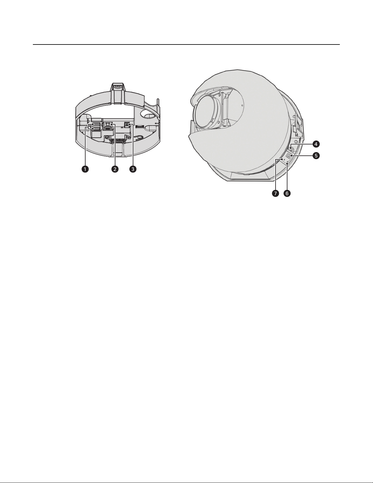
Figure 1. Connections and Features
ì
Accessory Ports: Connects with compatible Pelco accessories.
î
RJ-45 Network Port: Connects the camera to the IP network. Also supplies power to the camera through the network using
Power over Ethernet (PoE). Only use PoE if heater and blower operation is not required for the installation.
ï
24 VAC Power: Operates the heater and blower; 24 VAC is required for heater and blower operation. Also supplies power to the camera if
PoE is not available.
ñ
Power LED: Flashes green during the configuration sequence; glows solid green after the sequence is complete. The LED can be disabled.
If this LED glows red (solid or flashing), contact Pelco Product Support at 1-800-289-9100 (USA and Canada) or +1-559-292-1981
(international) for assistance.
ó
Reset Button: Reboots the camera or restores the camera’s factory default settings. This button is recessed. Using a small tool, such as a
paper clip, press and release the reset button once to reboot the camera. Press and hold the reset button for 10 seconds to restore the
camera to the factory default settings.
r
Ethernet Activity LED: Flashes green to indicate that data is being transmitted or received by the camera.
s
Ethernet Link LED: Glows solid amber to indicate that a live network connection is established.
10 C2267M (11/12)
Installation
You can install the Spectra HD Series dome system using one of the following methods:
• Installation in a suspended ceiling or a fixed ceiling. Refer to In-Ceiling Models on page 11.
• Installation using a pendant mount (not supplied). Refer to Pendant Models on page 15.
IN-CEILING MODELS
1. Locate the center point of the mounting location.
2. Insert the compass tool into the ceiling and draw a circle.
3. Cut out the circle.
4. Attach a conduit fitting (not supplied) and lock nut (not supplied).
5. Install a safety chain/cable (not supplied). The safety chain/cable should be capable of supporting up to 7.3 kg (16 pounds).
6. Pull the wiring into the back box through the conduit fitting.
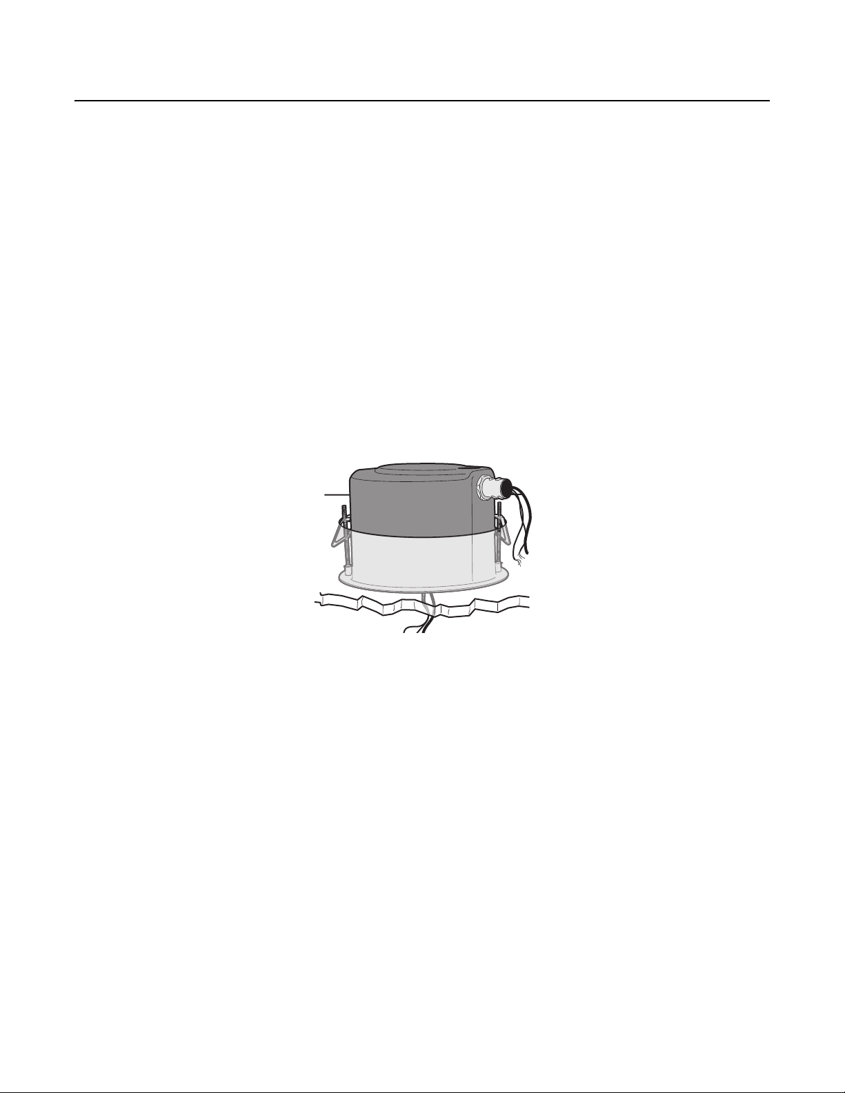
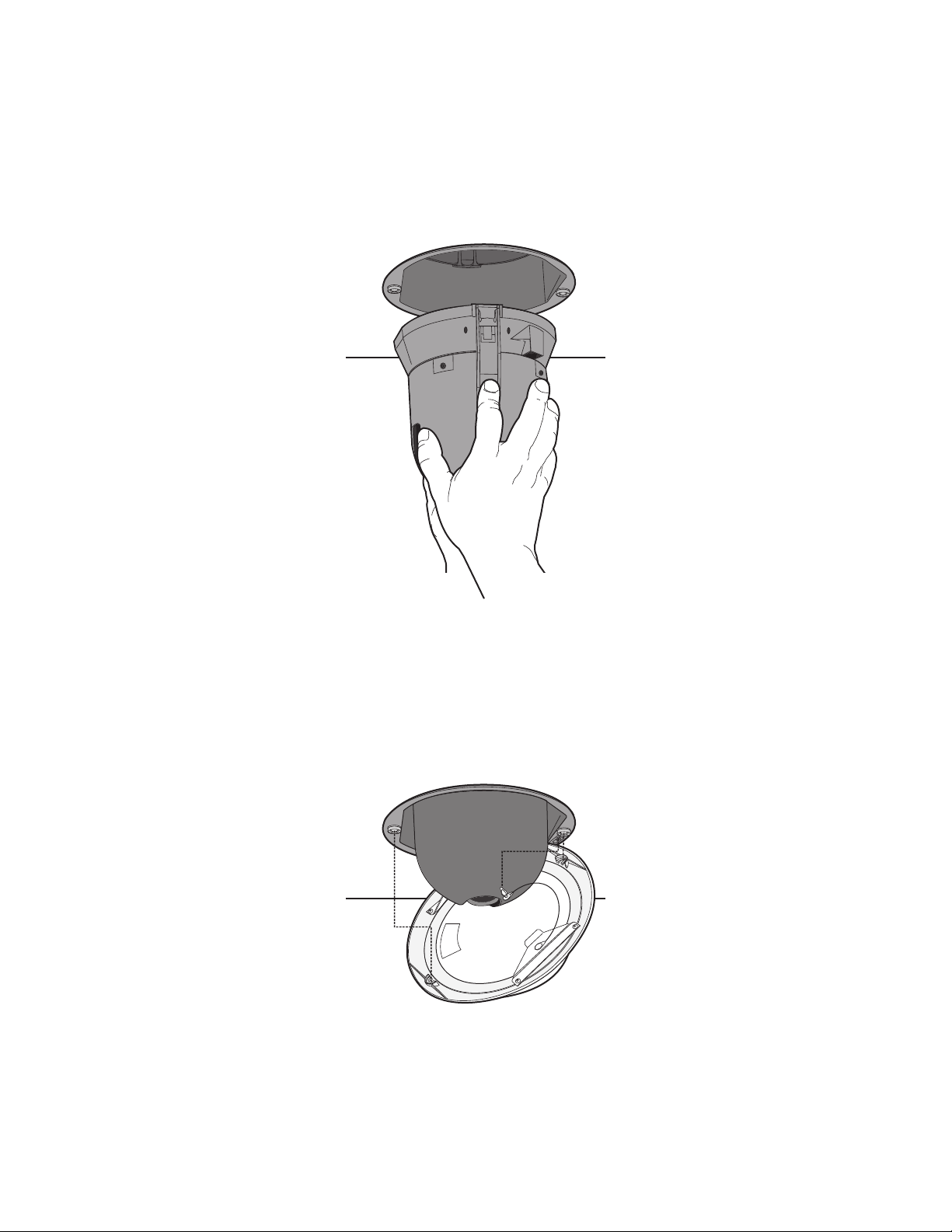
7. Install the back box:
a. Compress the spring clips and push the back box through the hole.
b. Tighten the screws until you hear a clicking noise.
Figure 2. Installing the Back Box: In-Ceiling Models
C2267M (11/12) 11
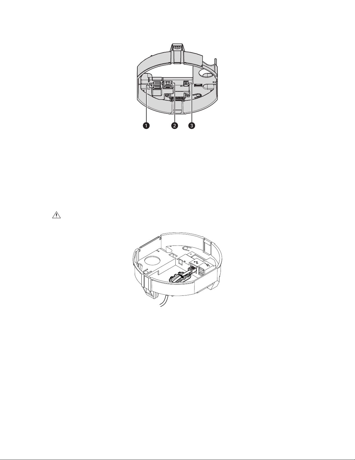
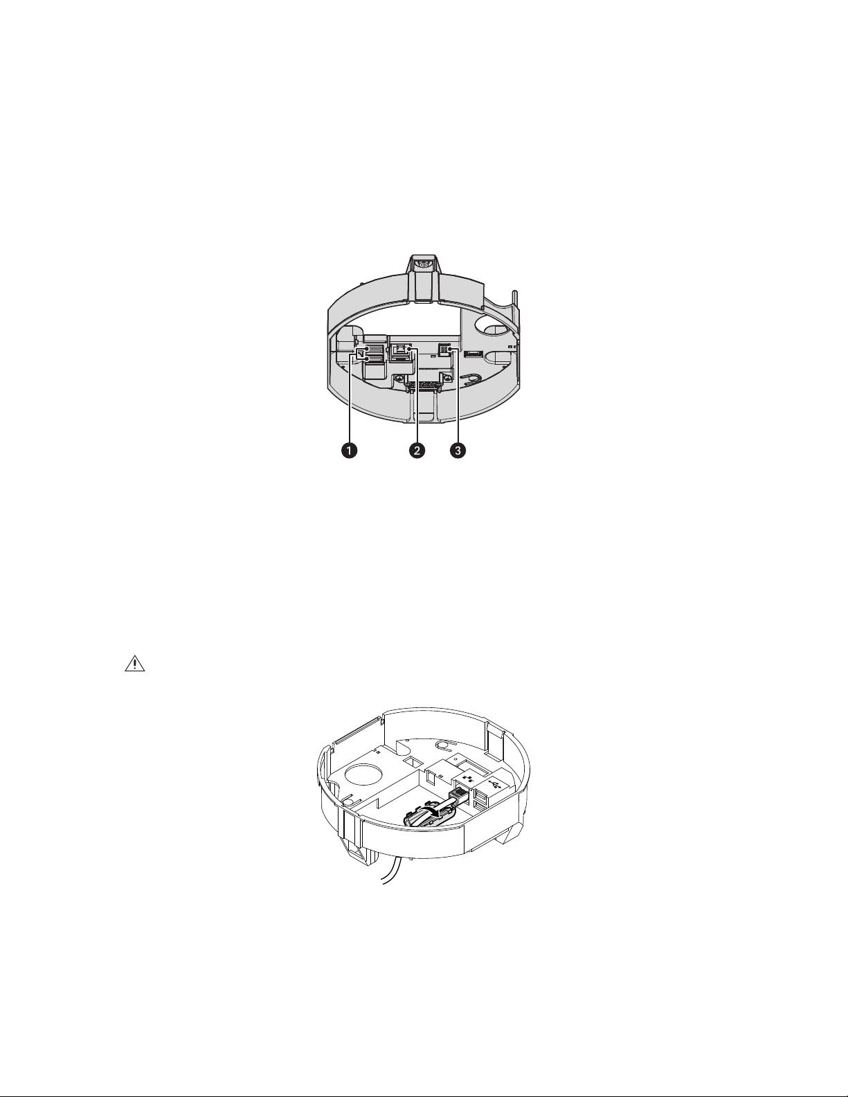
8. Connect the power wiring. Refer to Figure 3 and Wiring on page 17 for more information.
24V~
Figure 3. Power Wiring Connections: In-Ceiling Models
ì
Accessory Ports: Connects with compatible Pelco accessories.
î
RJ-45 Network Port: Connects the camera to the IP network. Also supplies power to the camera through the network using
Power over Ethernet (PoE). Only use PoE if heater and blower operation is not required for the installation.
ï
24 VAC Power: Operates the heater and blower; 24 VAC is required for heater and blower operation. Also supplies power to the
camera if PoE is not available.
9. FCC Class A installations: Attach the ferrite (supplied) to the network cable. Attach the ferrite on the cable as close as possible to the
camera’s RJ-45 network port.
WARNING: The ferrite must be installed for the camera to meet FCC Class A compliance standards. Failure to correctly install the ferrite
can cause harmful interference to radio communications.
Figure 4. Installing the Ferrite: In-Ceiling Models
12 C2267M (11/12)
10. Install the dome drive:
a. Line up the blue and red tabs on the dome drive with the blue and red arrows inside the back box.
b. Push in the tabs that are located on both sides of the dome drive.
c. Insert one side of the dome drive, and then insert the other.
d. Continue pushing on the dome drive until both sides click into place.
Figure 5. Installing the Dome Drive: In-Ceiling Models
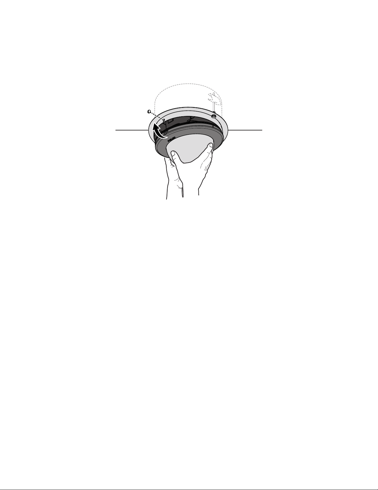
11. Install the lower dome:
Indoor Models
a. Snap the clip on the end of the trim ring leash into the hole on the lip of the back box.
b. Snap the trim ring onto the plastic snap washers on the back box mounting screws.
Figure 6. Installing the Lower Dome: In-Ceiling Indoor Models
C2267M (11/12) 13
Environmental Models
a. Attach the back box leash to the lower dome.
b. Align the back box screws with the slots on the lower dome.
c. Push the lower dome onto the back box.
d. Tighten the screws to secure the lower dome to the back box.
Figure 7. Installing the Lower Dome: In-Ceiling Environmental Models
12. Apply power to the dome. The dome system will complete a configuration sequence.
NOTE: If the system is not connected to a DHCP server and DHCP is enabled, the configuration sequence might take up to five minutes to
complete.
14 C2267M (11/12)
PENDANT MODELS
1. Install the pendant mount (not supplied). Refer to the instructions supplied with the mount.
2. Pull the wiring into the back box.
3. Screw the back box onto the pendant mount. If outdoors, apply thread compound (supplied) to the threads on the back box.
NOTE: Thread compound must be applied on both standard and environmental pendants. Not doing so may prevent the units from being
separated in the future.
4. Connect the power wiring. Refer to Figure 8 and Wiring on page 17 for more information.
Figure 8. Power Wiring Connections: Pendant Models
ì
Accessory Ports: Connects with compatible Pelco accessories.
î
RJ-45 Network Port: Connects the camera to the IP network. Also supplies power to the camera through the network using
Power over Ethernet (PoE). Only use PoE if heater and blower operation is not required for the installation.
ï
24 VAC Power: Operates the heater and blower; 24 VAC is required for heater and blower operation. Also supplies power to the
camera if PoE is not available.
5. FCC Class A installations: Attach the ferrite (supplied) to the network cable. Attach the ferrite on the cable as close as possible to the
camera’s RJ-45 network port.
WARNING: The ferrite must be installed for the camera to meet FCC Class A compliance standards. Failure to correctly install the ferrite
can cause harmful interference to radio communications.
24V~
Figure 9. Installing the Ferrite: Pendant Models
C2267M (11/12) 15
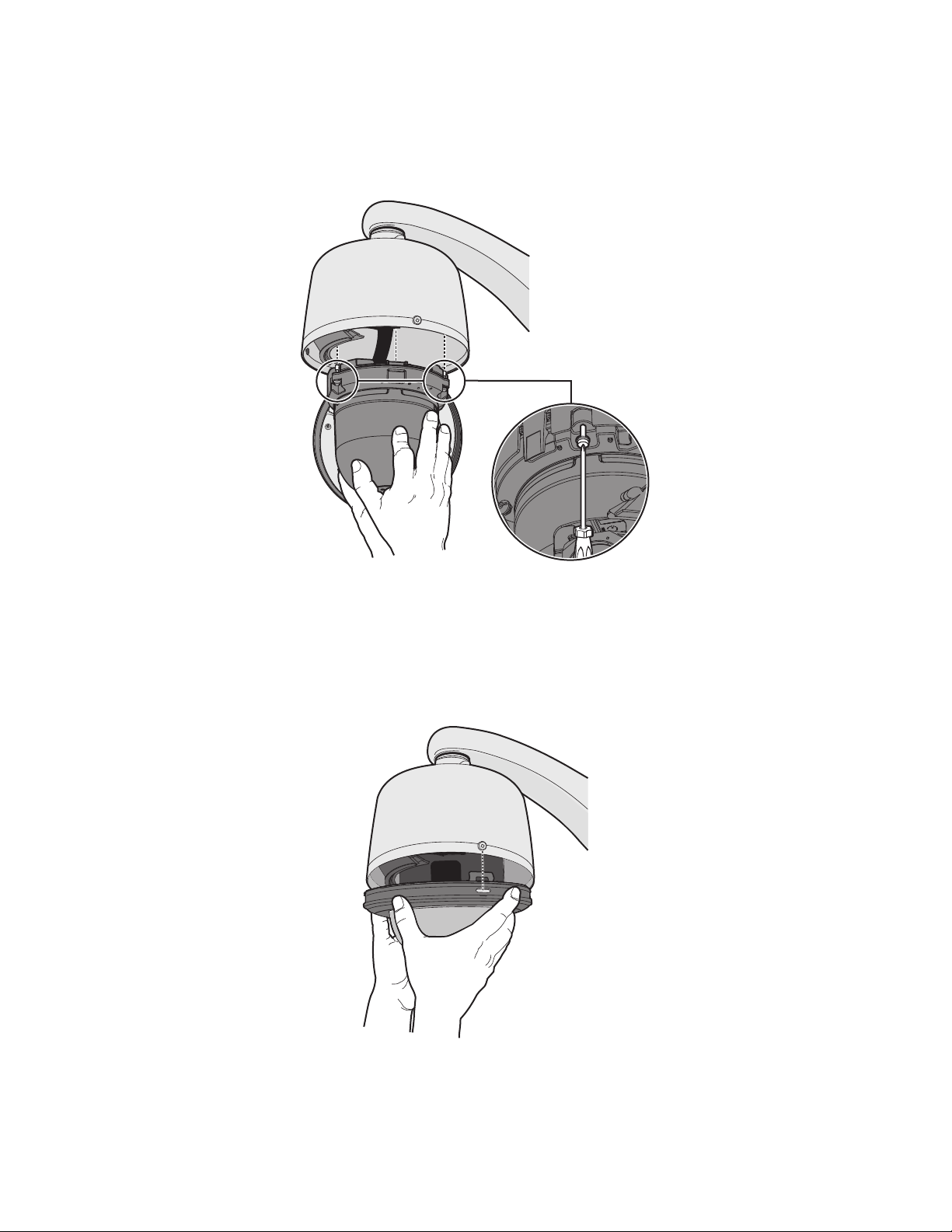
6. Install the pendant dome drive:
a. Line up the blue and red arrows on the pendant dome drive with the blue and red arrows inside the back box.
b. Push the pendant dome drive into the clips until both sides click into place. The clips temporarily hold the dome drive in place.
c. Place one hand on or under the dome until the fasteners are secure.
d. Screw in the three captive fasteners until they are secure.
Figure 10. Installing the Dome Drive: Pendant Models
7. Install the lower dome:
a. Attach the back box leash to the lower dome.
b. Align the back box screws with the slots on the lower dome.
c. Push the lower dome onto the back box.
d. Tighten the screws to secure the lower dome to the back box.
Figure 11. Installing the Lower Dome: Pendant Models
8. Apply power to the dome. The dome system will complete a configuration sequence.
NOTE: If the system is not connected to a DHCP server and DHCP is enabled, the configuration sequence might take up to five minutes to
complete.
16 C2267M (11/12)
WIRING
8
8
1
1
CAT5 REQUIREMENT FOR POE
Connect a Cat5 cable (not supplied) to the RJ-45 network port. The 8-pin port includes video and PoE for the camera. PoE (IEEE 802.3af) injects
power over the same cabling that carries the network data, eliminating the need for a separate power supply. This simplifies the installation and
operation of the camera without affecting network performance.
NOTES:
• The camera will autosense and configure itself to use either a crossover cable or a straight cable.
• Only use PoE if heater and blower operation is not required for the installation. The operating temperature range without the heater and
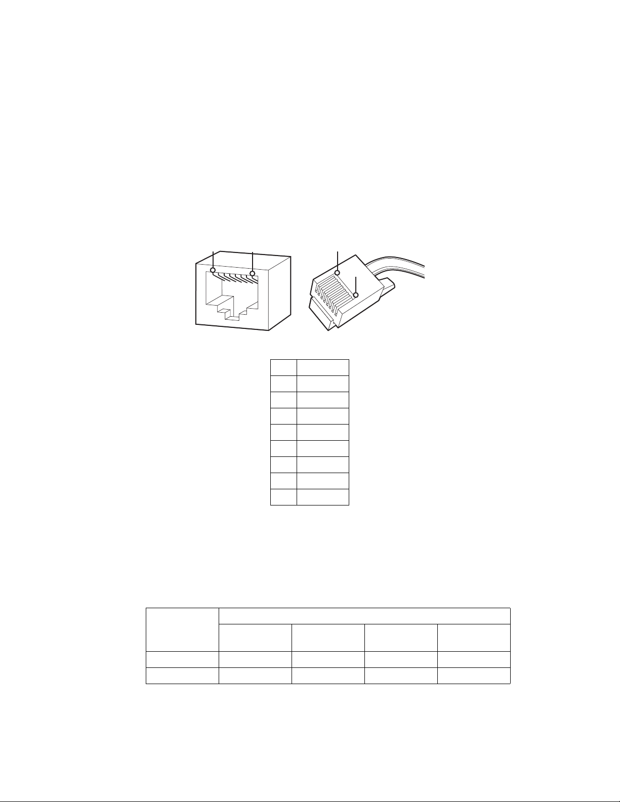
Refer to Figure 12 for pin descriptions.
blower is 0° to 50°C (32° to 122°F) for in-ceiling models and –4° to 45°C (25° to 113°F) for pendant models.
1
2
3
4
5
6
7
8
8
7
6
5
4
3
2
1
Table A. Cat5 Cable Pin Functions
Pin Function
1TX+
2TX–
3 RX+
4PoE 1-2
5PoE 1-2
6 RX–
7PoE 3-4
8PoE 3-4
Figure 12. Cat5 Cable Pin Descriptions
24 VAC
To operate the heater and blower inside the dome, 24 VAC power is required. Power consumption of the heater and blower is 72 VA. Use a 24
VAC transformer with a minimum of 100 VA per dome.
Table B. 24 VAC Wiring Distances
AC/DC Total VA/
Total Watts
20 AWG
(0.5 MM
2
)
(1.0 MM2)
23 VA/15 W 38 m (123 ft) 60 m (196 ft) 95 m (311 ft) 151 m (495 ft)
75 VA/65 W 12 m (39 ft) 19 m (62 ft) 30 m (98 ft) 48 m (156 ft)
18 AWG
Wire Gauge
16 AWG
(1.5 MM2)
14 AWG
(2.5 MM2)
NOTE: If you are operating the camera using 24 VAC and you are wiring more than one camera to the same transformer, connect one side of the
transformer to the red wire (24 VAC +) and connect the other side of the transformer to the black wire (24 VAC –). Failure to connect all modules
identically might introduce video noise for some installations.
C2267M (11/12) 17

Operation
CAMERA CONFIGURATION SEQUENCE
Once the device is installed and power is applied, the device undergoes a configuration sequence. The configuration sequence takes
approximately two minutes to complete, and then the device will come on line.
NOTE: If the device is not connected to a Dynamic Host Configuration Protocol (DHCP) server and DHCP is enabled, the configuration sequence
might take up to five minutes to complete.
Refer to the following sections for more information:
• Network Tab on page 29
• Turning On DHCP on page 31
• Turning Off DHCP on page 31
MINIMUM SYSTEM REQUIREMENTS
Processor: Intel® Core™ i3 Processor, 2.4 GHz
®
Operating system: Microsoft
or Mac® OS X 10.4 (or later)
Memory: 4 GB RAM
Network interface card: 100 megabits (or greater)
Windows® 7 (32-bit and 64-bit) with DirectX 11, Windows® XP Service Pack 3 with DirectX 9.0c,
Monitor: Minimum of 1024 x 768 resolution, 16- or 32-bit pixel color resolution
Web browser: Internet Explorer® 8.0 (or later) or Mozilla® Firefox® 3.5 (or later); Internet Explorer 8.0 (or later) is recommended for configuring
analytics
®
Media player: Pelco Media Player or QuickTime
(or later)
NOTES:
• Pelco Media Player is recommended for control, smoothness, and reduced latency as compared to QuickTime.
• This product is not compatible with QuickTime version 7.6.4 for Windows XP or Windows Vista. If you have this version installed on your PC,
you will need to upgrade to QuickTime version 7.6.5.
• Network and processor bandwidth limitations might cause the video stream to pause or appear pixelated when additional Web-interface
users connect to the camera. Decrease the images per second (ips), resolution, compression, or bit rate settings of the Web interface video
streams to compensate for network or processor limitations.
7.6.5 for Windows XP, Windows Vista, and Windows 7; or QuickTime 7.6.4 for Mac OS X 10.4
18 C2267M (11/12)

ACCESSING THE IP CAMERA
The first time you access the camera, the live video page appears. By default, you are viewing the video as a public user and only have access to
the single stream live view.
If, for security purposes, users should not be allowed to view video without first logging on to the camera, change the permissions for public
users.
LOGGING ON TO THE CAMERA
1. Open the Web browser.
2. Type the camera’s IP address in the browser address bar.
NOTE: If you do not know the camera’s IP address, you can locate it using the Pelco Device Utility software.
3. Click the Login button in the navigation bar; a dialog box opens.
4. Type your user name and password.
NOTE: If you are logging on to the camera as the administrator for the first time, the default user name and password are admin
(all lowercase). For security purposes, be sure to change the password after you log on for the first time.
5. Click Log In.
Refer to the following sections for more information:
• Live Video Page on page 20
• Settings Page on page 24
• System Tab on page 25
• Network Tab on page 29
• Imaging Tab on page 35
• A/V Streams Tab on page 45
• Users Tab on page 49
• Events Tab on page 52
C2267M (11/12) 19
Live Video Page
The live video page allows you to manage the way you view live video and capture images. You can also view live video from this page and
access menus on the navigation bar (based on user permissions).
NOTE: The PTZ controls are viewable only after you have logged on to the device.
Refer to the following sections for more information:
• Live Video Page Icons on page 20
• PTZ Controls on page 21
• Keyboard Shortcuts on page 21
• Selecting a Stream on page 22
• Taking a Snapshot on page 23
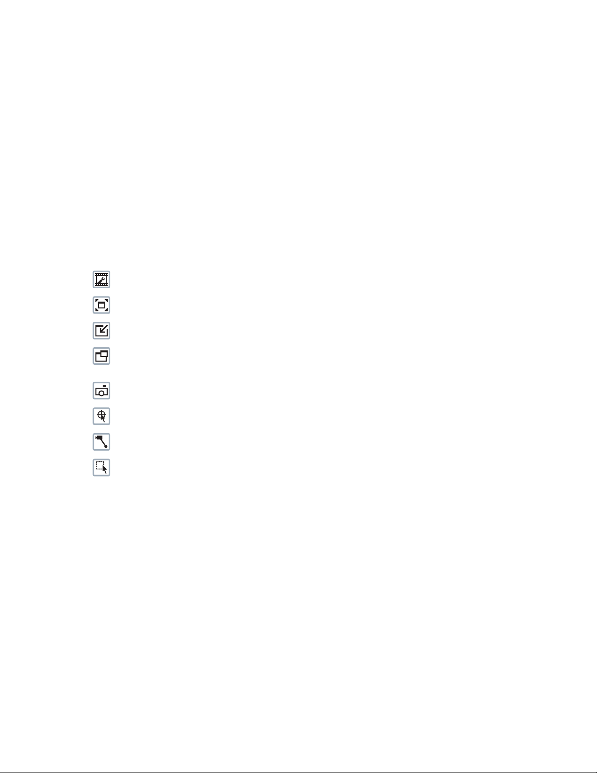
LIVE VIDEO PAGE ICONS
Viewable icons are based on user permissions.
Select Stream: Selects the viewable video stream that displays in live view (Primary, Secondary, QuickView, or Event) and selects
unicast or multicast and throttle settings.
Maximize Viewing Area: Scales the image to the full size of the browser. To resize the video pane to normal view, click the
Show Toolbar button in the upper-right corner of the window.
Show Toolbar: Returns the window to normal view. This icon is only available after the window has been set to maximize the
viewing area.
Open Stream in New Window: Opens the video in a scalable, independent window. Opening the video in a separate window allows
you to view the video while other applications are running. This window can be minimized, maximized, or closed using the title bar
buttons of the active window. The window can also be resized by dragging the lower-right corner of the window.
Take a Snapshot: Captures the image displayed in the video pane and saves it as a JPEG file.
Center Viewing Area*: Centers the camera on an area in the video pane. To center a viewing area, click the desired location in the
video pane.
Pan and Tilt*: Controls the pan and tilt functions. Click and drag the mouse to the left or right to pan the camera. Click and drag the
mouse up or down to tilt the camera.
Resize Viewing Area*: Zooms in on an area of interest. Click and drag the mouse over the view pane to zoom in on an object.
®
*These icons are always available when using the Pelco Media Player. If you are using QuickTime
QuickView Stream is selected.
, these icons are available only when the
20 C2267M (11/12)
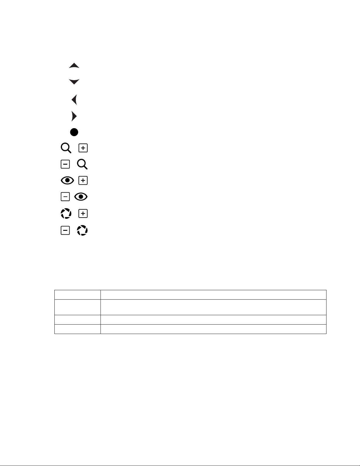
PTZ CONTROLS
NOTE: The PTZ controls are viewable only after you have logged on to the device.
Tilt Up: Click and hold the button to tilt the camera up.
Tilt Down: Click and hold the button to tilt the camera down.
Pan Left: Click and hold the button to pan the camera left.
Pan Right: Click and hold the button to pan the camera right.
Joystick: Click and hold the button to pan and tilt the camera. If you leave the mouse cursor over the
joystick button, you can use the mouse wheel to zoom the lens in and out.
Zoom In: Click and hold the button to zoom the lens in.
Zoom Out: Click and hold the button to zoom the lens out.
Focus Near: Click and hold the button to focus on an object near the camera.
Focus Far: Click and hold the button to focus on an object far away from the camera.
Iris Open: Click and hold the button to open the iris and lighten the image.
Iris Close: Click and hold the button to close the iris and darken the image.
KEYBOARD SHORTCUTS
Several keyboard shortcuts are available when viewing the primary stream on the live video page using Microsoft® Internet Explorer® and the
Pelco Media Player. These keyboard shortcuts display different overlays on a video pane and provide quick access to a specific function.
Keyboard Shortcut Function
SHIFT + A Displays analytics information for the currently active behavior. If there is no currently active behavior, this keyboard
shortcut has no effect.
SHIFT + S Displays details about the live video such as image rate, resolution, and bit rate.
SHIFT + T Displays the current date and time.
These keyboard shortcuts are not available when viewing video with Quicktime
Table C. Keyboard Shortcuts
®
.
C2267M (11/12) 21

SELECTING A STREAM
1. Click the Select Stream button.
2. Select one of the following streams from the Select Stream page:
Primary Stream: To select this stream, click the button next to Primary Stream.
Secondary Stream: To select this stream, click the button next to Secondary Stream.
QuickView Stream: To select this stream, click the button next to QuickView Stream.
Event Stream: To select this stream, click the button next to Event Stream.
NOTE: If the secondary stream has not been configured, only Primary Stream, Event Stream, and QuickView Stream are available.
3. Configure the display settings for the selected stream. Available display settings are determined by the video compression of the selected
stream:
H.264 compression: For the Primary Stream or Secondary Stream, select Unicast and Multicast from the Transmission drop-down menu.
JPEG compression: For the Secondary Stream or QuickView Stream, select Images Per Second (IPS) from the Throttle drop-down menu.
4. Click the Select button to save the stream settings.
Refer to the following sections for more information:
• Primary Stream and Secondary Stream on page 22
• QuickView Stream on page 22
• Event Stream on page 22
• Unicast on page 23
• Multicast on page 23
• Throttle on page 23
PRIMARY STREAM AND SECONDARY STREAM
The Primary Stream and Secondary Stream are video streams that include compression, resolution, image rate, and bit rate settings. The streams
can be set up using a video preset setting or they can be customized using the video configuration settings.
A video preset is a predefined video configuration that offers a good balance between video performance and bandwidth usage. For easy stream
configuration, use the Video Presets page located in the drop-down menu of the A/V Streams tab.
To customize the Primary Stream or Secondary Stream, select the Settings page and then use the Video Configuration page located in the dropdown menu of the A/V Streams tab. Configurable settings include the stream name, compression, resolution, image rate, bit rate, and I-frame
interval of the video streams. The default names for the streams are Primary Stream and Secondary Stream; however, if these stream names are
changed, the new names replace the default names (Primary Stream and Secondary Stream) on the Select Stream page.
QUICKVIEW STREAM
The QuickView Stream is a predefined JPEG video stream with a lower resolution. This low resolution, low frame rate stream is available when
the Imaging tab settings are being configured. This allows users to view changes to exposure, white balance, and other settings as they are
configured and before the settings are saved.
The QuickView Stream is also ideal for users who are connected to a network with processor bandwidth limitations that might cause a high
resolution, high frame rate video stream to pause or appear pixilated.
The aspect ratio of the QuickView Stream mirrors that of the Primary Stream.
EVENT STREAM
The Event Stream displays a list of alerts triggered by a running analytic behavior. The alert includes a screen capture, the profile that was
triggered, and the zone where the alert was detected. For the Event Stream to work you must have an analytic behavior profile running. To set up
and run analytic behaviors, profiles, and zones, use the Analytic Configuration page located in the drop-down menu of the Events tab.
22 C2267M (11/12)

UNICAST
A unicast transmission sends a separate video stream to each user that is requesting data. Although multiple users might request the same data
from the camera at the same time, duplicate video streams are transmitted to each user. Every unicast user that connects to the camera
consumes additional processing power, which limits the number of simultaneous users who can access the camera.
The camera supports a maximum of 20 simultaneous users.
MULTICAST
A multicast transmission sends data to multiple users at the same time using one transmission stream. Each multicast user that connects to the
camera consumes no additional processing power; therefore, multicast video streams can be sent to an unlimited number of simultaneous users.
THROTTLE
Throttle sets the upper limit on the image rate delivered to your computer. Lowering the throttle reduces the load on the network and on your
computer, which might be helpful when resources are limited.
TAKING A SNAPSHOT
1. Click the “Take a Snapshot” button.
2. A dialog box opens, allowing you to open or save the file.
3. Select one of the following options:
Open: Your computer’s photo editing program opens and displays the screen image. This function is available only when using
Microsoft
Save: The image is saved as a JPEG file at the location you specify.
Cancel: The captured image is not opened or saved and the dialog box closes.
NOTE: If you are using JPEG, the captured image is the size of the largest MJPEG stream. If you are using H.264, the image is captured using the
QuickView Stream, which is a low resolution image.
®
Internet Explorer® 7.0 (or later) or Mozilla® Firefox® 3.0 (or later).
C2267M (11/12) 23

Settings Page
Depending on user permissions, the Settings page allows you to manage camera system and network settings, set up users, configure events,
and control the camera imaging and streams.
NOTE: The Settings menu might not be available if the user does not have permission to access this feature.
ACCESSING THE CAMERA MENUS
1. Log on to the camera.
2. Click the Settings link in the navigation bar located in the upper-right corner of the page; a list of menu tabs appears.
3. Place your mouse pointer over a tab to display a list of submenus.
Refer to the following sections for more information:
• System Tab on page 25
• Network Tab on page 29
• Imaging Tab on page 35
• A/V Streams Tab on page 45
• Users Tab on page 49
• Events Tab on page 52
24 C2267M (11/12)

System Tab
Use the System tab to change general system settings, configure the time settings, set up the text overlay for the live view, configure backup and
restore, and display system information.
General System Settings
The general system settings page includes configurable fields for the device name, time settings, and text overlay settings. The device name is
the user-friendly description of the camera displayed in the gray area near the top of screen. The time server is an external server that uses
Network Time Protocol (NTP) to synchronize the camera date and time settings. The text overlay settings allow you to customize the appearance
of the video by displaying the device name, the date and time, and other overlays at the top or bottom of the video stream.
You can also use the general system settings page to turn the camera’s LEDs on or off and to configure the Simple Mail Transfer Protocol (SMTP)
server to send an email notification when an event handler is activated.
NOTE: Contact your network administrator for information on configuring email notification on your local network.
You can also use the general system settings page to generate a system log, reboot the camera, or restore the camera’s factory default settings.
Backup and Restore Settings
The backup and restore settings page includes configurable fields for backup and restore of camera settings. Once the camera settings have
been configured for optimal scene display, use the backup feature to save the camera settings. If the camera settings are changed and
inadvertently result in a less desirable image, use the restore feature to restore the camera to the previously saved settings.
NOTE: This feature is not intended for the configuration of multiple units or for firmware upgrades.
Information Settings
The information settings page includes read-only fields for the firmware version, hardware version, model number, and serial number of the
system. This information is typically required by Pelco Product Support for troubleshooting purposes.
Refer to the following sections for more information:
• Changing the Device Name on page 25
• Enabling LEDs on page 26
• Configuring the SMTP Server on page 26
• Configuring DHCP Time Server Settings on page 26
• Configuring Manual Time Server Settings on page 26
• Customizing the Appearance of the Text Overlay on page 27
• Generating a System Log on page 27
• Rebooting the Camera on page 27
• Restoring All Camera Defaults on page 27
• Downloading a Full Backup of Camera Settings on page 28
• Uploading a Backup File to Restore Camera Settings on page 28
CHANGING THE DEVICE NAME
1. Place your mouse pointer over the System tab.
2. Select General Settings from the drop-down menu.
3. Click the Device Name box and highlight the text.
4. Type a user-friendly name into the Device Name box (2 to 63 characters). A user-friendly name makes it easier to recognize the device on
the network. Examples of user-friendly names are Front Door, Lobby, or Parking Lot.
5. Click Save to save the new device name, or click Reset to restore to the previously saved device name.
C2267M (11/12) 25

ENABLING LEDS
1. Place your mouse pointer over the System tab.
2. Select General Settings from the drop-down menu.
3. Select On or Off beside the Enable LEDs button to turn the camera’s power LED on or off. The default setting is On.
4. Click Save to save the new setting, or click Reset to restore to the previously saved setting.
CONFIGURING THE SMTP SERVER
1. Place your mouse pointer over the System tab.
2. Select General Settings from the drop-down menu.
3. Click the SMTP Server box and type the address for the SMTP server used to deliver email from this camera's event system.
4. Click Save to save the new setting, or click Reset to restore to the previously saved setting.
CONFIGURING DHCP TIME SERVER SETTINGS
1. Place your mouse pointer over the System tab.
2. Select General Settings from the drop-down menu.
3. Select DHCP for the Time Server.
NOTE: Select DHCP if the camera is connected to a Dynamic Host Configuration Protocol (DHCP) network that has time server properties
configured. Selecting this option automatically synchronizes the camera with the time server. If the DHCP network’s time server properties
are not configured or the network does not have a time server, configure the DHCP settings manually.
4. Click the Save button to save the settings, or click the Reset button to clear all of the information you entered without saving it.
CONFIGURING MANUAL TIME SERVER SETTINGS
1. Place your mouse pointer over the System tab.
2. Select General Settings from the drop-down menu.
3. Select Manual for the Time Server.
4. Type the IP address of the time server in the Time Server box. The time server is an external server that uses Network Time Protocol (NTP)
to synchronize the camera date and time settings.
5. Configure the Time Zone by selecting the continent and region that are closest to the camera’s location from the Time Zone drop-down
menus.
NOTE: If your location observes a form of daylight saving time, the system automatically changes the time on the associated dates.
6. You can also specify time using an offset from Greenwich Mean Time (GMT) if you do not make a selection from the Time Zone drop-down
menu.
7. Click the Save button to save the settings, or click the Reset button to clear all of the information you entered without saving it.
26 C2267M (11/12)

CUSTOMIZING THE APPEARANCE OF THE TEXT OVERLAY
1. Place your mouse pointer over the System tab.
2. Select General Settings from the drop-down menu.
3. Set the Text Overlay settings:
Date/Time Overlay: Select Show to display the date and time in the live view overlay. The default setting is Hide.
Camera Name Overlay: Select Show to display the camera name in the live view overlay. The default setting is Hide.
Pan/Tilt Overlay: Select Show to display the pan, tilt, zoom, and direction position when moving the PTZ in the live view overlay. The
default setting is Hide.
4. Select the display position for the overlay from the Position drop-down menu. Selections include Top Right, Top Center, Top Left, Bottom
Right, Bottom Center, and Bottom Left.
5. View the selected overlays at the bottom of the Text Overlay section of the window.
6. If the Date/Time Overlay is set to Show, select the format for the date and time from the Overlay Format drop-down menu.
7. Click the Save button to save the settings, or click the Reset button to clear all of the information you entered without saving it.
GENERATING A SYSTEM LOG
1. Place your mouse pointer over the System tab.
2. Select General Settings from the drop-down menu.
3. Click the Generate System Log button.
4. A dialog box opens, allowing you to open or save the file.
5. Save the file to create a system log that can be used by Pelco Product Support for troubleshooting. Contact Pelco Product Support at
1-800-289-9100 (USA and Canada) or +1-559-292-1981 (international).
REBOOTING THE CAMERA
1. Place your mouse pointer over the System tab.
2. Select General Settings from the drop-down menu.
3. Click the Reboot Camera button to restart the camera. Rebooting the camera does not change the configured camera settings.
RESTORING ALL CAMERA DEFAULTS
WARNING: This process cannot be undone; all user and custom settings will be lost.
1. Place your mouse pointer over the System tab.
2. Select General Settings from the drop-down menu.
3. Click the Restore All Camera Defaults button to restore the camera’s factory default settings.
NOTE: If the camera is not connected to a Dynamic Host Configuration Protocol (DHCP) network, the IP address settings for the camera will be
lost and the server will not recognize the camera. The default setting for the camera IP address is DHCP On.
Refer to the following section for more information:
• Turning Off DHCP on page 31
C2267M (11/12) 27

DOWNLOADING A FULL BACKUP OF CAMERA SETTINGS
1. Place your mouse pointer over the System tab.
2. Select Backup and Restore from the drop-down menu.
3. Click the Download Now button. A file download dialog box opens.
4. Click Save and specify where you want to save the file.
5. Click OK to save the backup file, or click Cancel to stop the operation.
UPLOADING A BACKUP FILE TO RESTORE CAMERA SETTINGS
1. Place your mouse pointer over the System tab.
2. Select Backup and Restore from the drop-down menu.
3. Click the Browse button. A file upload dialog box opens.
4. Select the file you want to upload.
5. Click the Open button.
6. Click the “Upload and Restore” button.
NOTE: Restoring a backup file restarts the camera.
7. Click OK to restore the backup file, or click Cancel to stop the operation.
28 C2267M (11/12)

Network Tab
Use the Network tab to change the camera’s general network settings, select the Secure Sockets Layer (SSL) settings, enable Secure Shell (SSH),
configure 802.1x port security, and select Simple Network Management Protocol (SNMP) settings.
General Network Settings
The general network settings page includes configurable and read-only fields for network communication settings. Available settings include the
host name, ports, and Dynamic Host Configuration Protocol (DHCP) settings for IPv4. The port settings determine the ports over which the camera
communicates using HTTP, HTTPS, and RTSP protocols. The hardware address is read-only.
You can also enable or disable the DHCP server from the general network settings page. DHCP automatically assigns an IP address to the camera
if there is a DHCP server on the network. If DHCP is set to On, the IP address, subnet mask, gateway, and DNS server settings are read-only text.
If DHCP is set to Off, these settings must be manually changed. The default camera setting for DHCP is On.
SSL Settings
The SSL settings page includes SSL configuration modes and certificate generation. To ensure security on the Internet, all Web browsers provide
several security levels that can be adjusted for sites that use SSL technology to transmit data. SSL encrypts communications, making it difficult
for unauthorized users to intercept and view user names and passwords.
SSL requires signed certificates to determine if the Web browser accessing the camera has the required authentication. The camera can
generate a certificate signing request (CSR) that can be sent to a certificate authority for a signature (for example, VeriSign
a self-signed certificate using the Generate Self-Signed Certificate option.
®
), or it can generate
SSH Settings
The SSH settings page enables or disables SSH access to the camera. SSH is a user-enabled protocol that allows Pelco Product Support to log on
to and service the camera for advanced troubleshooting purposes. From the SSH settings page, users with the appropriate permissions can
enable or disable SSH access to the camera.
802.1x Settings
The 802.1x settings page enables or disables 802.1x port security, which authenticates devices that want to establish a point-to-point access
through a wired or wireless port using Extensible Authentication Protocol (EAP) protocols. This port-based authentication method prevents
unauthorized access to a Local Area Network (LAN) through a physical port. For example, when a device is connected to a network port, the
network switch asks the device for authentication. The device replies with its credentials. If the credentials are accepted, the network switch
opens the port for normal use. If authentication fails, the device is prevented from accessing information on the port.
SNMP Settings
The SNMP setting page includes SNMP configuration settings. SNMP is an application layer protocol used to manage TCP/IP-based networks
from a single workstation or several workstations. The camera supports SNMP versions 2c and 3 and can be configured to send data using a trap.
Refer to the following sections for more information:
• Changing the Host Name on page 30
• Configuring the HTTP Port on page 30
• Configuring the HTTPS Port on page 30
• Configuring the RTSP Port on page 30
• Turning On DHCP on page 31
• Turning Off DHCP on page 31
• Selecting the Secure Sockets Layer Mode on page 32
• Generating a Self-Signed Certificate on page 32
• Deleting a Self-Signed Certificate on page 32
• Generating a Certificate Request on page 33
• Enabling Secure Shell on page 33
• Configuring the 802.1x Port Security Settings on page 33
• Selecting SNMP Settings on page 34
C2267M (11/12) 29

CHANGING THE HOST NAME
1. Place your mouse pointer over the Network tab.
2. Select General from the drop-down menu.
3. View the read-only hardware address.
4. Click the Hostname box and highlight the text.
5. Type a user-friendly name into the Hostname box (1 to 21 characters) using alphanumeric characters. A user-friendly name makes it easier
to recognize the device on the network. Numeric-only names are not allowed.
6. Click the Save button to save the settings, or click the Reset button to clear all of the information you entered without saving it.
CONFIGURING THE HTTP PORT
NOTE: The HTTP port number must remain at the default setting of 80 when connecting to a Pelco video management system (VMS). If you are
connecting to a Pelco VMS, do not change the HTTP port setting.
1. Place your mouse pointer over the Network tab.
2. Select General from the drop-down menu.
3. Click the HTTP Port box and highlight the text.
4. Type a new port number for HTTP communications. The default setting is 80.
NOTE: Contact your network administrator before changing port settings to ensure they do not conflict with your network infrastructure.
5. Click the Save button to save the settings, or click the Reset button to clear all of the information you entered without saving it.
CONFIGURING THE HTTPS PORT
NOTE: Before configuring the HTTPS port, set the SSL configuration mode to either Optional or Required and install a security certificate.
1. Place your mouse pointer over the Network tab.
2. Select General from the drop-down menu.
3. Click the HTTPS Port box and highlight the text.
4. Type a new port number for HTTPS communications. The default setting is 443.
NOTE: Contact your network administrator before changing port settings to ensure they do not conflict with your network infrastructure.
5. Click the Save button to save the settings, or click the Reset button to clear all of the information you entered without saving it.
CONFIGURING THE RTSP PORT
NOTE: The camera uses the RTSP protocol to communicate with a video management system (VMS). Do not change the RTSP port unless you
are sure your VMS does not use the default RTSP port.
1. Place your mouse pointer over the Network tab.
2. Select General from the drop-down menu.
3. Click the RTSP Port box and highlight the text.
4. Type a new port number for RTSP communications. The default setting is 554.
NOTE: Contact your network administrator before changing port settings to ensure they do not conflict with your network infrastructure.
5. Click the Save button to save the settings, or click the Reset button to clear all of the information you entered without saving it.
30 C2267M (11/12)

TURNING ON DHCP
The default Dynamic Host Configuration Protocol (DHCP) setting for the camera is DHCP On. If DHCP is set to Off, complete the following steps to
reset it to On.
1. Place your mouse pointer over the Network tab.
2. Select General from the drop-down menu.
3. Select On for Dynamic Host Configuration Protocol (DHCP).
4. Click the Save button to save the settings, or click the Reset button to clear all of the information you entered without saving it.
NOTE: If the camera is not connected to a DHCP server but DHCP is set to On, the default IP address 192.168.0.20 on subnet mask 255.255.255.0
is automatically assigned to the camera. After the first camera is connected and assigned the default IP address, the system automatically looks
for other cameras on the auto IP address system and assigns IP addresses in sequential order as required. For example, if three cameras are
connected to a network without a DHCP server, the first camera is assigned address 192.168.0.20, the second camera is assigned address
192.168.0.21, and the third camera is assigned address 192.168.0.22.
TURNING OFF DHCP
WARNING: Contact your network administrator to avoid any network conflicts before setting or changing the IP address of the device.
1. Place your mouse pointer over the Network tab.
2. Select General from the drop-down menu.
3. Select Off for the Dynamic Host Configuration Protocol (DHCP).
4. Change the following network settings as required:
IP Address: The address of the camera connected to the network.
Subnet Mask: The address that determines the IP network to which the camera is connected (relative to its address).
Gateway: The router that accesses other networks.
DNS Servers: The addresses of the dedicated servers that translate the names for Web sites and host names into numeric IP addresses.
5. Click the Save button to save the settings, or click the Reset button to clear all of the information you entered without saving it.
C2267M (11/12) 31

SELECTING THE SECURE SOCKETS LAYER MODE
1. Place your mouse pointer over the Network tab.
2. Select SSL from the drop-down menu.
3. Select one of the following modes:
Disabled: Turns off access to the Web client through SSL. Sensitive data is not encrypted during transmission. The default setting is
disabled.
NOTE: If the SSL mode is set to disabled, you cannot access the camera using a URL that begins with an “https:” protocol. Your Web
browser displays an error message if you do not type the camera URL correctly.
Optional: A signed SSL certificate must be installed, but a secure URL that begins with the protocol name “https:” is optional when
accessing the camera. You can also access the camera using a standard URL with the “http:” protocol, but sensitive data is not encrypted
during transmission. To ensure that sensitive data is encrypted, you must use a secure URL with the “https:” protocol.
Required: A signed Secure Sockets Layer (SSL) certificate must be installed, and a secure URL that begins with the protocol name “https:”
must be used to access the camera. Sensitive data is always encrypted during transmission. A URL that begins with the “http:” protocol
rather than the “https:” protocol is redirected to the secure URL automatically.
NOTE: Beginning with firmware version 1.8.2, this mode cannot be modified in the Web browser. To select or clear the Required mode, you
must use the ONVIF or Pelco API call. Doing so avoids placing the camera into a mode in which it would no longer work with a connected
VMS system.
Refer to the following sections for more information:
• Generating a Self-Signed Certificate on page 32
• Deleting a Self-Signed Certificate on page 32
• Generating a Certificate Request on page 33
GENERATING A SELF-SIGNED CERTIFICATE
1. Place your mouse pointer over the Network tab.
2. Select SSL from the drop-down menu.
3. Click the Install New Certificate button located at the bottom of the SSL Configuration page. The Select Certificate Install Method buttons
appear on the page.
4. Select Generate Self-signed Certificate and then click Next. The Generate Self-signed Certificate form opens.
5. Fill in all of the fields, and then click the Generate Certificate button.
6. After the certificate is uploaded to the device, select the desired mode.
7. Click the Save button to save the settings, or click the Reset button to clear all of the information you entered without saving it.
NOTE: Self-signed certificates are valid for one year. The certificate’s expiration date is listed in the “Valid from” and To fields in the Certificate
section of the window. If the certificate has expired and you attempt to access the camera using a secure URL, the Web browser displays a
message. Repeat this procedure to generate and upload a new certificate.
DELETING A SELF-SIGNED CERTIFICATE
1. Place your mouse pointer over the Network tab.
2. Select SSL from the drop-down menu.
3. Verify the certificate in the Certificate section of the window.
4. Click the Delete Certificate button.
5. Click the Save button to save the settings, or click the Reset button to clear all of the information you entered without saving it.
32 C2267M (11/12)

GENERATING A CERTIFICATE REQUEST
1. Place your mouse pointer over the Network tab.
2. Select SSL from the drop-down menu.
3. Click the Install New Certificate button located at the bottom of the SSL Configuration page. The Select Certificate Install Method buttons
appear on the page.
4. Select Generate Certificate Request, and then click Next. The Generate Certificate Signing Request form opens.
5. Fill in all of the fields, and then click Generate Request. The following progress message appears on the page: “Generating certificate
signing request, please wait.”
6. Send the CSR, which looks like an encrypted block of undecipherable text, to a third-party certificate authority of your choice for a
signature. You will receive a signed certificate.
7. Click Choose File and browse to locate the certificate on your computer.
8. Click Open once you locate and select the certificate.
9. Click Upload Certificate to upload the signed certificate to the device.
10. After the certificate is uploaded, select the desired mode.
11. Click the Save button to save the settings, or click the Reset button to clear all of the information you entered without saving it.
NOTE: Depending on the third-party certificate authority that signed your certificate, you might need to renew your certificate after a specified
amount of time. Consult the certificate authority for more details.
ENABLING SECURE SHELL
1. Place your mouse pointer over the Network tab.
2. Select SSH from the drop-down menu.
3. Select the Enabled check box.
4. Click the Password box and type a password (4 to 16 alphanumeric characters). Passwords are case-sensitive.
NOTE: The default user name is “root” and cannot be changed. The user name and password are required when accessing the camera
through a third-party SSH client.
5. Click the “Re-type Password” box and retype your password.
6. Click the Save button to save the password and enable SSH, or click the Reset button to clear all of the information you entered without
saving it.
CONFIGURING THE 802.1X PORT SECURITY SETTINGS
WARNING: To prevent network conflicts, contact your network administrator before configuring the 802.1x port security settings.
1. Place your mouse pointer over the Network tab.
2. Select 802.1x from the drop-down menu.
3. Select On for the 802.1x port security. The default setting for 802.1x port security is Off.
4. Select the Extensible Authentication Protocol (EAP) method from the Protocol drop-down menu. Supported EAP methods include EAP-MD5,
EAP-TLS, EAP-TTLS, EAP-PEAP, and EAP-FAST.
5. Type the information required for the selected 802.1x EAP method.
6. Connect the PC to a 802.1x secured switch that has the same EAP method.
7. Click the Save button to save the settings, or click the Reset button to clear all of the information you entered without saving it.
C2267M (11/12) 33

SELECTING SNMP SETTINGS
WARNING: The Simple Network Management Protocol (SNMP) settings are advanced controls. Contact your network administrator to
obtain the required information to configure SNMP settings.
1. Place your mouse pointer over the Network tab.
2. Select SNMP from the drop-down menu.
3. Select the SNMP version to configure: No SNMP Server, SNMP V2c, or SNMP V3. The default setting is No SNMP Server, which disables
the SNMP configuration.
NOTE: SNMP V2c and SNMP V3 configuration settings are independent of each other, but only one SNMP version can be active at a time.
CONFIGURING SNMP V2C
1. Place your mouse pointer over the Network tab.
2. Select SNMP from the drop-down menu.
3. Select SNMP V2c for the SNMP version.
4. Type the community name in the Community String box. The default name for the Community String is ”public.”
5. Configure the Trap Configuration settings:
Address: Type the host name or IP address of the recipient of the trap message.
Community String: Type the name of the community that should receive the trap message.
6. Click the Save button to save the settings, or click the Reset button to clear all of the information you entered without saving it.
CONFIGURING SNMP V3
1. Place your mouse pointer over the Network tab.
2. Select SNMP from the drop-down menu.
3. Select SNMP V3 for the SNMP version.
4. View the read-only Engine ID, which is a unique string that identifies the device to SNMP V3.
5. Type the SNMP user name in the SNMP user box.
6. Select the encryption algorithm for authentication from the Authentication drop-down menu: None, MD5, or SHA. If you use authentication
method MD5 or SHA, type a password in the box to the right of the selected Authentication encryption.
7. Select the privacy encryption algorithm setting from the Privacy drop-down menu: None, DES, or AES. If you use privacy method DES or
AES, type a password in the Privacy text box.
8. Type the address for the Trap Configuration in the Address text box. The Address is the host name or IP address of the recipient of the trap
message.
9. Click the Save button to save the settings, or click the Reset button to clear all of the information you entered without saving it.
34 C2267M (11/12)

Imaging Tab
Use the Imaging tab to change the camera’s general image settings, adjust the camera exposure, tune the white balance settings for scenes with
fluctuating lighting conditions, define window blanking privacy areas, configure presets and preset tours, and select positioning settings.
General Imaging Settings
The general imaging settings page includes adjustments for freeze frame, digital zoom, focus settings, and digital processing.
Freeze frame settings freeze the previewed image when a preset is called, which allows for smooth transition from one preset scene to another.
Preset freeze frame also reduces bandwidth and guarantees that blanked areas are not revealed when a preset is called.
Digital zoom settings allow the camera to zoom 240X (12X digital and 20X optical) or stop at 20X optical.
Focus settings adjust the autofocus, sure focus, and focus trace. Digital processing settings adjust the device’s sharpness, saturation, contrast,
and brightness and include Quick Setup and Noise Reduction settings.
Exposure Settings
The exposure settings page includes adjustments for exposure, day and night, backlight compensation, and wide dynamic range (WDR)
processing.
Exposure is the amount of light detected by the camera sensor. A scene with correct exposure settings has adequate detail and contrast between
white and dark values. An image with too little or too much exposure eliminates detail in the scene.
Day/night settings control the position of the IR cut filter, which determines the color or black-white setting of the camera. Day/night settings
change depending on the exposure settings.
Backlight compensation enhances objects in the center of the picture. The device uses the center of the picture to adjust the iris. If a bright
backlight is present, the subjects in the picture might appear dark or as a silhouette. If there is a bright light source outside of this area, it might
wash out to white. The device adjusts the iris so that the object in the sensitive area is properly exposed.
WDR processing balances the brightest and darkest sections of a scene to produce a picture that is better balanced in lighting and provides more
detail.
White Balance Settings
The white balance settings page defines how the camera processes video images to render true colors in a scene. White balance is especially
effective in scenes with changing lighting conditions or in scenes with more than one type of light source. For example, scenes that benefit from
white balance correction are outdoor scenes, indoor scenes that include a window or door that opens to the outdoors, or indoor scenes that
include both incandescent and fluorescent lighting.
Window Blanking Settings
The window blanking settings page configures window blanks that conceal user-defined privacy areas. A blanked area appears on the screen as
a solid gray window. The device can handle up to 32 blanked windows.
Presets Settings
The presets settings page configures presets, which are predetermined viewing areas (such as doors) that a device goes to automatically when
instructed, either by an operator giving a simple command or a software program issuing an instruction. A maximum of 255 presets can be
configured for the device. Presets are available while viewing video.
Preset Tours Settings
The preset tours settings page configures a preset tour, which is a grouping of presets that displays each predetermined viewing area in the
sequence for a determined length of time before displaying the next preset. A preset tour can contain a maximum of 16 presets in any order, and
presets can be repeated anywhere in the sequence.
Positioning Settings
The positioning settings page includes configurable settings for pan/tilt speed, pan center point, pan limit stops, and tilt limit stops. The pan/tilt
speed settings control the pan and tilt speeds. The pan center point sets the center point to the pan angle displayed in the video preview pane on
the right side of the window. The pan and tilt limit stops control the pan and tilt range of the camera. When limit stops are set, a pan or tilt
operation stops when a limit is reached.
C2267M (11/12) 35

Refer to the following sections for more information:
• Changing Freeze Frame Settings on page 36
• Enabling Digital Zoom on page 37
• Changing the Focus Settings on page 37
• Changing the Digital Processing Settings on page 38
• Selecting Normal Exposure Settings on page 38
• Selecting Exposure Time and Gain Control Settings on page 39
• Day Night Settings on page 39
• Selecting Backlight Compensation on page 40
• Selecting Wide Dynamic Range Processing on page 40
• Selecting the White Balance Mode on page 40
• Turning On Window Blanking on page 41
• Turning Off Window Blanking on page 41
• Deleting a Window Blanking Area on page 41
• Restoring Window Blanking Defaults on page 41
• Creating a Preset on page 42
• Deleting a Preset on page 42
• Creating a Preset Tour on page 42
• Deleting a Preset from a Tour on page 43
• Deleting a Preset Tour on page 43
• Configuring Pan/Tilt Speed Control on page 43
• Configuring the Pan Center Point (Azimuth Zero) on page 43
• Configuring the Pan Limit Stops on page 44
• Configuring the Tilt Limit Stops on page 44
CHANGING FREEZE FRAME SETTINGS
1. Place your mouse pointer over the Imaging tab.
2. Select General from the drop-down menu.
3. Select the Freeze Frame mode:
On: The camera image freezes when a preset is called. When the device reaches the preset, the image is unfrozen and the preset scene
appears.
Off: The camera image is never frozen. The default setting is Off.
4. If required, click the “Restore Settings to Defaults” button to restore the default settings, or click the Restore All Imaging Settings button to
restore all the imaging settings.
36 C2267M (11/12)

ENABLING DIGITAL ZOOM
1. Place your mouse pointer over the Imaging tab.
2. Select General from the drop-down menu.
3. Select the Digital Zoom mode:
On: Zoom goes up to 240X (12X digital and 20X optical). The default setting is On.
Off: Zoom stops at 20X optical.
4. If required, click the “Restore Settings to Defaults” button to restore the default settings, or click the Restore All Imaging Settings button to
restore all the imaging settings.
CHANGING THE FOCUS SETTINGS
1. Place your mouse pointer over the Imaging tab.
2. Select General from the drop-down menu.
3. Select the Auto Focus setting:
On: The camera automatically focuses during runtime operation. The default setting is On.
Off: The camera does not automatically focus during runtime operation. If the Focus Trace setting is On and the Auto Focus setting is Off,
the camera does not perform autofocus but does perform focus trace corrections while the tilt angle changes during runtime operation. If
the Focus Trace setting is Off and the Auto Focus setting is Off, the camera is in manual focus.
4. Select the Sure Focus setting:
On: The camera only performs one Auto Focus function when the pan, tilt, and zoom (PTZ) motion is complete. When autofocus lock is
acheived, autofocus is turned off and the position is kept until the next PTZ motion. If 30 seconds pass without an autofocus lock, the Auto
Focus operation is turned off until the next PTZ motion. Finally, if the IR cut filter changes state, another Auto Focus function occurs.
Off: The camera continuously checks if the video is in focus. If the camera is not in focus, the focus is adjusted. The default setting is Off.
5. Select the Focus Trace setting:
On: The camera selects the focus trace curve when zooming, based on the distance to ground-level targets in the scene. If the Auto Focus
setting is Off, the camera adjusts the focus position in real time, based on the the distance to ground-level targets in the scene.
Off: The camera selects from many possible trace curves when zooming. The default setting is Off.
6. Move the slider for Install Height to the desired position, between 1 m and 305 m. The slider is used by the Focus Trace setting to
determine distances to targets in the scene. To achieve proper focus positioning for Focus Trace, set the Install Height to the installation
height of the camera in meters. The default setting is 305 m.
7. If required, click the “Restore Settings to Defaults” button to restore the default settings, or click the Restore All Imaging Settings button to
restore all the imaging settings.
C2267M (11/12) 37

CHANGING THE DIGITAL PROCESSING SETTINGS
1. Place your mouse pointer over the Imaging tab.
2. Select General from the drop-down menu.
3. Select Quick Setup:
Normal: Selects a normal amount of image quality. The sliders for Sharpness Adjust, Saturation Adjust, Contrast Adjust, and Brightness
Adjust are set to zero (0). The default setting is Normal.
Vivid: Selects a vivid amount of image quality that enhances colors, lightens whites, and darkens blacks. The sliders for Sharpness Adjust,
Saturation Adjust, Contrast Adjust, and Brightness Adjust are set at 50, 25, -25, and 25 respectively.
Custom: Lets you select a custom amount of image quality. Move the sliders described in Table 5 to achieve the desired image quality.
NOTE: If you select Normal or Vivid and then move a slider, the mode switches to Custom.
4. Select Noise Reduction:
Off: Turns noise reduction off. Video noise in low light is not reduced.
Normal: Selects a normal amount of video noise reduction in low light. The default setting is Normal.
High: Selects a greater amount of video noise reduction in low light.
5. Move the slider to the left or right to change the following settings:
Sharpness Adjust: Controls the clarity of detail in a scene. Move the slider to the right to increase the sharpness; move the slider to the
left to decrease the sharpness. Increasing the sharpness also increases the image noise. The range of adjustment is –100 to 100; the
default setting is 0 (zero).
Saturation Adjust: Controls how intense or vivid the colors are in a scene. Move the slider to the right to increase the saturation level;
move the slider to the left to decrease the saturation level. The range of adjustment is –100 to 100; the default setting is 0 (zero).
Contrast Adjust: Controls gradations between the darkest and lightest portions of the scene. Move the slider to the right to increase the
contrast; move the slider to the left to decrease the contrast. The range of adjustment is –100 to 100; the default setting is 0 (zero).
Brightness Adjust: Controls the lighting detail in a scene. Move the slider to the right to lighten the image; move the slider to the left to
darken the image. The range of adjustment is –100 to 100; the default setting is 0 (zero).
6. If required, click the “Restore Settings to Defaults” button to restore the default settings, or click the Restore All Imaging Settings button to
restore all the imaging settings.
SELECTING NORMAL EXPOSURE SETTINGS
1. Place your mouse pointer over the Imaging tab.
2. Select Exposure from the drop-down menu.
3. Select the Normal mode.
NOTE: The available Day Night settings are dependent on the exposure mode.
4. Move the Max Gain slider to the desired position. Increasing the gain increases the brightness of the image, but it also increases the
amount of noise in the image. The maximum gain is 2 to 29 dB. The default setting is 28 dB.
5. Move the Max Exposure Time slider to the desired position. This setting is the maximum time in milliseconds that the sensor is exposed to
the light. Decreasing the maximum exposure time decreases the light sensitivity and reduces motion blurring. Increasing the maximum
exposure time increases light sensitivity and also increases motion blurring.
Available maximum exposure settings include 33.33, 66.67, 125, and 250 msec. The default setting is 33.33 msec.
6. If required, click the “Restore Settings to Defaults” button to restore the default settings.
38 C2267M (11/12)

SELECTING EXPOSURE TIME AND GAIN CONTROL SETTINGS
1. Place your mouse pointer over the Imaging tab.
2. Select Exposure from the drop-down menu.
3. Select the Exposure Time/Gain Control mode.
4. Move the Max Gain slider to the desired position. Increasing the gain increases the brightness of the image, but it also increases the
amount of noise in the image. The maximum gain range is 0 to 29 dB. The default setting is 28 dB.
5. Move the Exposure Time slider to the desired position. This setting is the time in milliseconds that the sensor is exposed to the light.
Decreasing the exposure time decreases the light sensitivity and reduces motion blurring. Increasing the exposure time increases light
sensitivity and also increases motion blurring.
Available exposure settings include 0.1, 0.25, 0.5, 1, 2, 4, 5.56, 8, 10, 16.67, 33.33, 66.67, 125, and 250 msec. The default setting is 66.67
msec.
6. If required, click the “Restore Settings to Defaults” button to restore the default settings.
DAY NIGHT SETTINGS
The Day Night mode controls the position of the IR cut filter, which determines the color or black-white setting of the camera. The Day Night
mode settings change depending on the Exposure settings. If the camera is set to Normal exposure mode, the Day Night mode can be set to Auto
or Manual and all of the respective settings are available. If the camera is set to Exposure Time/Gain Control mode, the only available Day Night
mode setting is Position, which sets the IR filter to either the day (color) position or the night (black-white) position.
SELECTING DAY NIGHT AUTO MODE
1. Place your mouse pointer over the Imaging tab.
2. Select Exposure from the drop-down menu.
3. Select Auto for the Day Night mode. The auto setting automatically controls the IR cut filter depending on the Transition Level setting.
4. Move the Transition Level slider to the desired position. The Transition Level setting determines when the device changes from day mode
(color) to night mode (black-white). Moving the slider to the left or right changes the transition level to a lighter or darker setting. A lighter
Transition Level setting changes modes at a high lux setting. The default setting is 2.
5. If required, click the “Restore Settings to Defaults” button to restore the default settings.
SELECTING DAY NIGHT MANUAL MODE
1. Place your mouse pointer over the Imaging tab.
2. Select Exposure from the drop-down menu.
3. Select Manual for the Day Night mode. The manual mode sets the IR cut filter to a fixed position depending on the position setting.
Available settings include:
Day: Sets the IR filter to the day (color) position.
Night: Sets the IR filter to the night (black-white) position.
4. If required, click the “Restore Settings to Defaults” button to restore the default settings.
C2267M (11/12) 39

SELECTING BACKLIGHT COMPENSATION
1. Place your mouse pointer over the Imaging tab.
2. Select Exposure from the drop-down menu.
3. Select On for the Back Light Compensation mode. Back Light Compensation enhances objects in the center of the picture when a bright
backlight is present and the subjects in the picture appear dark or as a silouette. When Back Light Compensation is on, the Wide Dynamic
Range Processing feature is unavailable. The default setting is Off.
4. If required, click the “Restore Settings to Defaults” button to restore the default settings.
SELECTING WIDE DYNAMIC RANGE PROCESSING
1. Place your mouse pointer over the Imaging tab.
2. Select Exposure from the drop-down menu.
3. Select On for the Wide Dynamic Range Processing mode. Wide Dynamic Range (WDR) evens out a scene where part of the scene is bright
and part is dark. When Wide Dynamic Range Processing is On, the Back Light Compensation feature is unavailable. The default setting is
Off.
4. If required, click the “Restore Settings to Defaults” button to restore the default settings.
SELECTING THE WHITE BALANCE MODE
1. Place your mouse pointer over the Imaging tab.
2. Select White Balance from the drop-down menu.
3. Select one of the following Mode settings:
Normal: This setting is recommended for most lighting conditions. The default setting is Normal.
Extended Color Temp: This setting maintains color balance in outdoor settings where sodium vapor lighting is widely used, such as
parking lots or street lights.
Manual: This setting is useful when the lighting in the scene does not change (for example, in a mall or casino). Manual mode allows
manual adjustment of the image output in the red and blue range. Move the Red Gain or the Blue Gain slider to the right to increase the
color level; move a slider to the left to decrease the color level. As you move a slider, the color changes on your monitor. The manual range
of adjustment for both color levels is 0 to 32.
4. If required, click the “Restore Settings to Defaults” button to restore the default settings.
40 C2267M (11/12)

TURNING ON WINDOW BLANKING
1. Place your mouse pointer over the Imaging tab.
2. Select Window Blanking from the drop-down menu.
3. Select On for Window Blanking.
4. If necessary, select On for Blanking Protection. Blanking protection limits the PTZ speed to ensure that blanked parts of the scene are not
visible when the camera moves.
5. Draw a window in the Live Preview area of the page:
a. Hold down the left mouse button.
b. Drag the mouse diagonally across the area you want to blank.
c. A color-coded box appears in the Edit Window section of the page that is the same color as the window drawn in the Live Preview
area.
NOTE: Up to 32 blanked windows can be defined.
6. If necessary, use the PTZ controls to reposition the camera to an alternate view.
7. To resize the window, click and drag one or more of the points until the window is the desired shape and size.
8. Click the Save button to save the settings, or click the Reset button to clear all of the information you entered without saving it.
TURNING OFF WINDOW BLANKING
1. Place your mouse pointer over the Imaging tab.
2. Select Window Blanking from the drop-down menu.
3. Select Off for Window Blanking.
4. Click the Save button to save the settings, or click the Reset button to clear all of the information you entered without saving it.
DELETING A WINDOW BLANKING AREA
1. Place your mouse pointer over the Imaging tab.
2. Select Window Blanking from the drop-down menu.
3. In the Edit Window area of the page, click the Delete button “X” next to the window blanking area you want to delete.
4. Click the Save button to save the settings, or click the Reset button to clear all of the information you entered without saving it.
RESTORING WINDOW BLANKING DEFAULTS
1. Place your mouse pointer over the Imaging tab.
2. Select Window Blanking from the drop-down menu.
3. Click the ”Restore Settings to Defaults” button. All defined windows are deleted, and the Window Blanking and Blanking Protection
settings are restored to the default settings of Off.
C2267M (11/12) 41

CREATING A PRESET
1. Place your mouse pointer over the Imaging tab.
2. Select Presets from the drop-down menu.
3. Click the New Preset button.
4. Type a name in the Preset Name box.
5. Select the Focus Lock mode:
On: A focus setting for the camera is saved with the predetermined viewing area and is used whenever the preset is selected. Choosing
this mode ensures that the camera uses the expected focal point any time the preset is selected.
Off: The preset does not retain any of the focus settings. Choosing this mode means that the camera uses any current focus setting when
the preset is selected.
WARNING: If an operator has changed the focus of the camera before the preset is selected, it is possible that the camera will be out of
focus when the camera displays the preset position later. Turn on the Focus Lock mode to avoid this problem.
6. Position the camera using the pan and tilt controls.
7. If necessary, adjust the zoom and focus.
8. Click the Save button to save the settings, or click the Reset button to clear all of the information you entered without saving it.
DELETING A PRESET
1. Place your mouse pointer over the Imaging tab.
2. Select Presets from the drop-down menu.
3. Select the preset that you want to delete from the Presets list.
4. Click the Delete Preset button.
CREATING A PRESET TOUR
1. Place your mouse pointer over the Imaging tab.
2. Select Preset Tours from the drop-down menu.
3. Click the New Tour button.
4. Type a name in the Tour Name box.
5. Select a preset from the list at the bottom of the page and drag it to the “Tour workspace” section of the window.
6. Set the dwell time for the preset. Dwell time can be set in minutes and seconds. Dwell time is the length of time (in minutes or seconds)
before the system moves to the next preset of the tour.
7. Move the Transition Speed slider to set the transition speed faster or slower.
8. Use the “Transition preview” pane to review the tour. Click the angle brackets icon (>>) to see additional presets. This icon is located
beneath the lower-right corner of the “Transition preview” pane.
9. Select another preset from the list and drag it to the right or left of an existing preset in the “Tour workspace” area. The border to either
side of the existing preset changes to yellow to indicate that you can add a preset at that location.
10. Continue adding presets to the tour. Be sure to add the dwell time and transition speed for each additional preset. Any preset can be added
to the tour; the same preset can be added several times.
11. If required, click the Refresh Selected Thumbnails button to refresh the selected preset thumbnails, or click Refresh All Thumbnails to
refresh all the preset thumbnails.
12. Click the Save button to save the settings, or click the Reset button to clear all of the information you entered without saving it.
42 C2267M (11/12)

DELETING A PRESET FROM A TOUR
1. Place your mouse pointer over the Imaging tab.
2. Select Preset Tours from the drop-down menu.
3. Select a tour in the Tours list.
4. In the “Tour workspace” area, locate the preset thumbnail you want to delete from the tour.
5. Click the Delete button ”X” next to the name of the preset.
6. Click the Save button to save the settings, or click the Reset button to clear all of the information you entered without saving it.
DELETING A PRESET TOUR
1. Place your mouse pointer over the Imaging tab.
2. Select Preset Tours from the drop-down menu.
3. Select a tour in the Tours list
4. Click the Delete Tour button.
CONFIGURING PAN/TILT SPEED CONTROL
1. Place your mouse pointer over the Imaging tab.
2. Select Positioning from the drop-down menu.
3. Select the Pan/Tilt Speed Control:
A: Linear: Pan and tilt speeds operate in a linear fashion. Speeds start slowly and ramp up evenly to medium and then to fast speeds.
B: Default: Pan and tilt speeds operate in an exponential fashion. Speeds start very slowly and ramp up quickly to very fast speeds. The
default setting is Default.
Refer to the graph of Speed versus Joystick Movement in the web user interface.
CONFIGURING THE PAN CENTER POINT (AZIMUTH ZERO)
1. Place your mouse pointer over the Imaging tab.
2. Select Positioning from the drop-down menu.
3. Click the left and right arrow buttons next to the video preview pane on the right side of the window to pan the camera to the desired
location.
4. Select the Go To Pan Center Point button to set the center point to the pan angle displayed in the video preview pane on the right side of the
window.
5. Select the Set New Pan Center Point button to set a new pan center point to the pan angle displayed in the video preview pane on the right
side of the window.
6. If required, click the Restore Default Center Point button to reset the pan center point to the 0 (zero) degree default.
C2267M (11/12) 43

CONFIGURING THE PAN LIMIT STOPS
1. Place your mouse pointer over the Imaging tab.
2. Select Positioning from the drop-down menu.
3. Select On for Pan Limit Stops. The default setting is Off.
4. Configure the left and right pan limits using one of the following methods:
• Type a value in degrees into the Left Pan Limit and Right Pan Limit boxes.
• Click the Get Current Pan button to configure the Left Pan Limit and Right Pan Limit boxes with the pan angle displayed in the video
preview pane on the right side of the window.
5. Click the Save button to save the settings, or click the Reset button to clear all of the information you entered without saving it.
CONFIGURING THE TILT LIMIT STOPS
1. Place your mouse pointer over the Imaging tab.
2. Select Positioning from the drop-down menu.
3. Select On for Tilt Limit Stops. The default setting is Off.
4. Configure the top and bottom tilt limits using one of the following methods:
• Type a value in degrees into the Top Tilt Limit and Bottom Tilt Limit boxes.
• Click the Get Current Tilt button to configure the Top Tilt Limit and Bottom Tilt Limit boxes with the tilt angle displayed in the video
preview pane on the right side of the window.
5. Click the Save button to save the settings, or click the Reset button to clear all of the information you entered without saving it.
44 C2267M (11/12)

A/V Streams Tab
Use the A/V Streams tab to configure the video and audio streams for the camera. The A/V Streams tab includes video presets settings, and
video and audio configuration.
Video Presets Settings
The video preset settings page includes three fully-configured video presets, High, Medium, and Low, which include primary and secondary video
stream settings for easy setup. These presets can also be used as a starting point for a custom video configuration. These preset configurations
vary depending on camera model.
Video Configuration Settings
The video configuration settings page allows you to customize the compression, resolution, image rate, bit rate, and I-frame interval of the video
streams. The default names for the streams are Primary Stream and Secondary Stream. Although each stream can be configured independently,
the settings of one stream can limit the options available to the other stream, depending on the processing power used.
NOTE: Always configure the primary stream before the secondary stream. The primary stream should always be the most resource-intensive of
the streams.
Audio Configuration Settings
The audio configuration settings page allows you to setup the internal audio device or an external audio device. The default setting for audio is
disabled, which means that no audio is transmitted from the camera. When enabled, audio is transmitted from the camera to the PC. Based on
your system configuration, images and audio might not be synchronized.
Not all camera models are equipped with an internal audio device. Refer to the specifications for your camera model for information.
NOTE: Improper use of audio/visual recording equipment might subject you to civil and criminal penalties. Applicable laws regarding the use of
such capabilities vary between jurisdictions and might require, among other things, express written consent from the recorded subjects. You are
solely responsible for insuring strict compliance with such laws and for strict adherence to any/all rights of privacy and personalty.
Refer to the following sections for more information:
• Selecting a Video Preset Configuration on page 45
• Configuring a Custom Video Stream Configuration on page 46
• Compression Standards on page 46
• Resolution on page 46
• Image Rate on page 46
• Bit Rate on page 47
• I-Frame Interval on page 47
• Quality of Service for Differentiated Services Code Point on page 47
• Endura Signing on page 47
• Profile on page 47
• GOP Structure on page 47
• Selecting Audio Configuration Settings on page 48
SELECTING A VIDEO PRESET CONFIGURATION
1. Place your mouse pointer over the A/V Streams tab.
2. Select Video Presets from the drop-down menu.
3. Click the button next to the desired video preset stream configuration.
4. Click the Save button to save the settings, or click the Reset button to clear your selection without saving it.
C2267M (11/12) 45

CONFIGURING A CUSTOM VIDEO STREAM CONFIGURATION
1. Place your mouse pointer over the A/V Streams tab.
2. Select Video Configuration from the drop-down menu.
3. Click both of the Clear buttons to delete the primary and secondary streams settings.
4. Optional: In the Primary Stream section, type a user-friendly name in the Name box (2 to 64 characters). A user-friendly name makes it
easier to recognize the stream (for example, Live and Recording).
5. Configure the Compression Standard, Resolution, Image Rate, Bit Rate, and I-frame Interval settings for the primary stream.
NOTE: The compression standard, resolution, image rate, bit rate, and I-frame interval settings are dependent on each other. You must first
decide the priority setting before you configure a stream. For example, if you want an image rate of 30 ips, set the image rate before you
configure the other settings.
6. Configure QoS (DSCP) Codepoint, Endura Signing, Profile, and GOP Structure.
7. Repeat steps 3 to 5 for the Secondary stream.
8. Click the Save button to save the settings, or click the Reset button to clear all of the information you entered without saving it.
COMPRESSION STANDARDS
JPEG: A commonly used video compression scheme. JPEG has the least impact on the camera’s processor, but it requires the most bandwidth.
MJPEG: Another video compression scheme, motion JPEG, in which video is compressed into JPEG images. When bandwidth is low, image
resolution is given priority.
H.264: A new version of MPEG-4 compression used in high-definition video players such as Blu-ray™ and HD-DVD. H.264 is the most
processor-intensive, but it requires the least amount of bandwidth.
RESOLUTION
Refer to the following table for the resolution capabilities of your camera model.
Table D. Available Camera Resolution
Camera Model 2.0 Megapixel
1920 x 1080
1280 x 720
Available
Resolutions
800 x 448
640 x 352
480 x 272
320 x 176
IMAGE RATE
The image rate is the number of images per second (ips) available for the video stream configuration. Available image rates depend upon the
model of the device that you are using.
NOTE: The maximum image rate setting might not be obtainable due to the compression standard and the resolution of the stream.
Refer to the following section for more information:
• Specifications on page 72
46 C2267M (11/12)

BIT RATE
The bit rate is the quality of the video stream (rendered in kilobits per second). The higher the value, the higher the video quality and bandwidth
required.
NOTE: When you change any of the video stream configuration settings, the camera automatically adjusts the bit rate. If you manually reduce
the bit rate lower than the camera's automatic setting, the image quality might be reduced and the stream selection options might be limited.
I-FRAME INTERVAL
The I-frame interval configures the number of partial frames that occur between full frames in the video stream. For example, in a scene where a
door opens and a person walks through, only the movements of the door and the person are stored by the video encoder. The stationary
background that occurs in the previous partial frames is not encoded, because no changes occurred in that part of the scene. The stationary
background is only encoded in the full frames. Partial frames improve video compression rates by reducing the size of the video. As the I-frame
interval increases, the number of partial frames increases between full frames. Higher values are only recommended on networks with high
reliability. This setting is only available with H.264.
QUALITY OF SERVICE FOR DIFFERENTIATED SERVICES CODE POINT
Quality of Service (QoS) for Differentiated Services Code Point (DSCP) is a code that allows the network to prioritize the transmission of different
types of data. This setting is only available with H.264.
NOTES:
• If you are not familiar with DSCP, contact your network administrator before changing this setting.
• Your network must be configured to use QoS. If you are unsure if your network is QoS-aware, contact your network administrator.
ENDURA SIGNING
Enabling the Endura Signing feature allows an Endura® system to authenticate video from an Endura recorded stream. This setting is only
available with H.264.
PROFILE
The profile defines the subset of bit stream features in an H.264 stream, including color reproduction and additional video compression. It is
important that the selected profile is compatible with the recording device so that a stream can be decoded and viewed.
Baseline: A simple profile with a low compression ratio. A baseline profile is compatible with more recorders but uses more bits to compress
quality video than the other profiles. This profile supports I-frames and P-frames. Use the baseline profile in applications with limited scene
changes; for example, an indoor scene with a single, unchanging primary light source and minimal motion.
Main: An intermediate profile with a medium compression ratio. The default setting is main. This profile is compatible with most recorders and
uses fewer bits to compress video than the baseline profile; however, it uses more bits than the high profile. The main profile supports I-frames,
P-frames, and B-frames.
High: A complex profile with a high compression ratio. This is the primary profile for high-definition television applications; for example this is
the profile adopted for Blu-ray and HD-DVD. The high profile supports I-frames, P-frames, and B-frames.
GOP STRUCTURE
The group of pictures (GOP) structure is the sequence in which frames are placed within a video stream. The GOP structure always includes
intra-coded frames (I-frames) and predictive coded frames (P-frames), but it can also include bi-directionally predictive coded frames (B-frames).
Each GOP structure starts with an I-frame: an image of the complete scene that is used as the reference frame in the structure. P-frames record
data changes that are different than the previous frame. This allows the video encoder to save space since the data of the I-frame is not
duplicated. B-frames not only capture data changes from the previous frame, but they also capture the data changes from the frame after the
B-frame. B-frames are more compressed than P-frames and require more processing power to be decoded.
The camera can be configured to use one of the following GOP structures:
IP: A compression that uses only I-frames and P-frames to provide low latency and a high level of decoder support. This GOP structure is
compatible with more recorders and decoders than IBBrBP.
IBBrBP: The most sophisticated H.264 compression available. IBBrBP provides the highest quality image at a given bit rate, but it also increases
the latency of the video and requires more processing power for decoders.
C2267M (11/12) 47

SELECTING AUDIO CONFIGURATION SETTINGS
To use audio with the camera if it does not have built-in audio support, you must connect an audio device to the accessory port. Once the device
is connected, audio can only be enabled through the primary stream.
Audio and video may not be synchronized when viewing and listening to the primary stream through a Web browser. You may experience a
three-second delay in video when viewing the primary stream with audio.
NOTE: Improper use of audio/visual recording equipment may subject you to civil and criminal penalties. Applicable laws regarding the use of
such capabilities vary between jurisdictions and may require, among other things, express written consent from the recorded subjects. You are
solely responsible for insuring strict compliance with such laws and for strict adherence to any/all rights of privacy and personalty.
1. Place your mouse pointer over the A/V Streams tab.
2. Select Audio Configuration from the drop-down menu.
3. Select Enabled in the Audio section.
4. Select the audio device setting from the Audio Device drop-down box.
USB Line In: Enables audio from a microphone connected to the USB accessory port.
Native Line In: (Only available with specific Sarix technology products that have built-in audio. Refer to the specifications for your product
model for information.) Enables audio from a microphone connected to the audio-in connector.
Native Microphone In: (Only available with specific Sarix technology products that have built-in audio. Refer to the specifications for
your product model for information.) Enables audio from the internal microphone.
5. Select the sample rate from the Sample Rate drop-down box. The sample rate is the quality of the audio stream (rendered in hertz per
second). The higher the value, the higher the audio quality. Available sample rate settings are 8000 Hz and 12000 Hz. The default setting is
8000 Hz.
6. Select the encoding method for the audio device from the Encoding drop-down box. Available encoding methods are PCMU, PCMA, and
PCM16. The default setting is PCMU.
7. Click the button next to Echo Cancellation (Enabled or Disabled) that you want to select.
8. If required, click the button next to Mute to mute the audio device.
NOTE: Do not use the mute button on an audio device, as it will override the audio software settings. To mute the audio device, select
Mute located on the Audio Configuration page.
9. Set the sensitivity of the input level by moving the Input Level slider. Move the slider to the right to increase the sensitivity level; move it to
the left to decrease the sensitivity level. For example, if the camera is installed in a noisy environment or the connected microphone has a
built-in line amplifier, set the sensitivity to a low setting. The setting range is 0 to 100.
10. Click the Save button to save the settings, or click the Reset button to clear all of the information you entered without saving it.
48 C2267M (11/12)

Users Tab
Use the Users tab to create and manage user accounts and to change the way the camera manages the users settings.
General Users Settings
The general users settings page sets the open or closed authentication mode. With open authentication, users can view video and use the
camera API without validating user credentials. With closed authentication, users must log on to the camera with a user name and password.
The general users settings page also allows you to change the way the camera manages users and groups. These settings can be managed on a
camera-to-camera basis (local mode) or by using a centralized server to apply changes to multiple cameras (remote mode).
Users Settings
The users settings page defines the access levels assigned to individuals logged on to the camera. Use this page to create, modify, or delete user
accounts for Administrators, Managers, Operators, and Viewers. User accounts are created to limit permissions.
Refer to the following sections for more information:
• Selecting the Users and Groups Settings on page 49
• Enabling Remote Mode on page 50
• Creating a New User on page 50
• Editing a User on page 51
• Deleting a User on page 51
SELECTING THE USERS AND GROUPS SETTINGS
1. Place your mouse pointer over the Users tab.
2. Select General Settings from the drop-down menu.
3. Select one of the following Authentication modes:
Open Authentication: Allows users to view video and use the camera API without validating user credentials. When Open Authentication
is selected, you can select “Require password for PTZ control” to limit PTZ control to authenticated users.
Closed Authentication: Requires users to possess valid credentials to view video and access the camera API. Before selecting Closed
Authentication, ensure that your video management system supports Closed Authentication mode.
4. Select one of the following User and Group Management modes to manage permissions of users and groups:
Local Mode: The camera manages users and groups locally. Any changes to users and groups affect only the camera that you are
accessing. The default setting is Local Mode.
Remote Mode: The camera authenticates and manages users through a Lightweight Directory Access Protocol (LDAP) server supported by
Microsoft
Selecting Remote Mode disables Local Mode and all management is done on the server.
5. Click the Save button to save the settings, or click the Reset button to clear all of the information you entered without saving it.
®
Active Directory®. This allows administrators to tie cameras and group permissions into existing single sign-on services (SSO).
WARNING: Remote Mode settings are advanced controls. Contact your network administrator to obtain the required information to
configure remote settings.
C2267M (11/12) 49

ENABLING REMOTE MODE
1. Place your mouse pointer over the Users tab.
2. Select General Settings from the drop-down menu.
3. Select Remote Mode. The default setting is Local Mode.
4. Type the IP address or host name of the LDAP server in the LDAP Server box.
5. Type the port over which the camera communicates with the LDAP server in the LDAP Port box. The default port for LDAP communications
is 389.
6. Type the distinguished name (DN) that is the basis for LDAP searches in the Base DN box.
7. Provide the template to format the user name (provided when the user logs on to the camera) for searches in the LDAP directory in the Bind
DN Template box.
8. Provide the LDAP search query for users found in the base DN in the Search Template box. The search must match an entry in the LDAP user
record to the bind name (user name).
9. Type the Group Mappings for each of the camera’s four user groups:
a. Type the common name (CN) and DN for the group of users to whom you want to grant admin access in the Admins box.
b. Type the CN and DN for the group of users to whom you want to grant manager access in the Managers box.
c. Type the CN and DN for the group of users to whom you want to grant operator access in the Operators box.
d. Type the CN and DN for the group of users to whom you want to grant viewer access in the Viewers box.
10. Type the credentials of a user who can be authenticated through the LDAP server in the User and Password boxes.
NOTE: Remote Mode (LDAP authentication) will not be enabled if you leave these boxes blank or do not provide valid credentials; this
ensures that you cannot lock yourself out of the camera with invalid or incorrect LDAP settings.
11. Click the Save button to save the settings, or click the Reset button to clear all of the information you entered without saving it.
CREATING A NEW USER
1. Place your mouse pointer over the Users tab.
2. Select Users from the drop-down menu.
3. Select the Access Level for the user.:
Admins: Permissions include access to all camera settings.
Managers: Permissions include access to all settings except this user cannot modify user permissions or restore factory default settings.
Operators: Permissions include view video, use PTZ functions, and use the API.
Viewers: Permissions include view video and use the API.
4. Click the Username box and type a user name (2 to 32 alphanumeric characters). User names are not case-sensitive and are saved in
lowercase characters.
5. Click the Password box and type a password (4 to 64 alphanumeric characters). Passwords are case-sensitive.
6. Click the Retype Password box and retype your password.
7. Click the Save button to save the settings and create a new user (the new user profile appears in the Users box on the left side of the page),
or click the Reset button to clear all of the information you entered without saving it.
50 C2267M (11/12)

EDITING A USER
1. Place your mouse pointer over the Users tab.
2. Select Users from the drop-down menu.
3. Click the user profile that you want to edit from the Users box on the left side of the page.
4. If required, select a different Access Level for the user.
5. Double-click in each of the password boxes to highlight the text. Type the new information in each password box.
NOTE: The Username cannot be modified; this box is read-only.
6. Click the Save button to save the settings, or click the Reset button to clear all of the information you entered without saving it.
DELETING A USER
1. Place your mouse pointer over the Users tab.
2. Select Users from the drop-down menu.
3. Click the user profile that you want to delete from the Users box located on the left side of the page.
4. Click the Delete User button. A dialog box opens and the following message appears “Are you sure you want to delete this user?”
5. Click OK. The user profile is deleted from the Users box.
NOTE: The “admin” user cannot be deleted.
C2267M (11/12) 51

Events Tab
Use the Events tab to configure camera events and analytics.
Events are activated by user-defined event sources that tell the camera how to react when an event occurs. Event handlers are the actions that
the camera takes when an event occurs. For example, a system source can be configured to send email to an operator if the system shuts down
and restarts.
Sources Settings
The sources settings page defines the camera functions that are automatically triggered by an event source. The camera supports Alarm,
Analytics, Park Action, System, and Timer sources. The Alarm source is the camera input for an external signaling device, such as a door contact
or motion detector. The Analytics source triggers when any configured behavior is detected. The Park Action source activates a user-defined
event if the camera is inactive for a specified period of time. The System source is activated when the camera restarts. The Timer source is a
user-defined event that activates an event after a specified amount of time.
Handlers Settings
The handlers settings page defines the actions that a camera takes when an event occurs. The camera supports Send Email, Upload JPEG to FTP
Server, Go to Preset, Open/Close Relay, and Run Tour handlers. The Send Email handler sends an email to a defined email address when an event
is activated. The Upload JPEG to FTP Server handler saves a JPEG of the activated event to a defined FTP server. The Go to Preset handler moves
the camera to a user-defined preset. The Open/Close Relay handler sends a signal to an external device when an alarm or relay is triggered. The
Run Tour handler starts a user-defined preset tour.
NOTE: The Pelco Alarm accessory must be connected to the camera’s accessory port for Open/Close Relay to work.
Analytic Configuration Settings
The analytic configuration settings page includes behaviors for which you can create custom profiles that contain different camera settings. With
these profiles, you can set up different scenarios for the behavior that automatically detects and triggers alarms when the specific activity is
detected.
Pelco analytics can be configured and enabled using a standard Web browser. The camera is preloaded with user-configurable behaviors and is
capable of running several behaviors at the same time. The number of behaviors is limited to the available processing power of the camera.
Available processing power is determined by the settings for compression standards, resolution, image rate, bit rate, and analytic configuration.
Pelco analytics are also compatible with Endura® or a third-party system that supports alarms using Pelco’s API. Refer to the specific product
documentation for instructions on how to configure and enable Pelco analytics.
NOTE: Analytic alerts can be seen in the event stream, but alarms are only transmitted through Pelco’s API.
Pelco analytics include the following behaviors:
Abandoned Object: Detects objects placed within a defined zone and triggers an alarm if the object remains in the zone longer than the
user-defined time allows.
Adaptive Motion: Detects and tracks objects that enter a scene and then triggers an alarm when the objects enter a user-defined zone. The
objects are monitored until they exit the scene.
AutoTracker: Detects and tracks movement in the camera’s field of view. When the AutoTracker behavior is configured, the system
automatically pans and tilts to follow the moving object until the object stops or disappears from the monitored area.
Camera Sabotage: Detects contrast changes in the field of view. An alarm is triggered if the lens is obstructed by spray paint, a cloth, or if it is
covered with a lens cap. Any unauthorized repositioning of the camera also triggers an alarm.
Directional Motion: Generates an alarm in a high traffic area when a person or object moves in a specified direction. For example, when a
camera is pointed at an exit door, if someone tries to enter through the exit door, an alarm triggers.
Loitering Detection: Identifies when people or vehicles remain in a defined zone longer than the user-defined time allows. This behavior is
effective in real-time notification of suspicious behavior around ATMs, stairwells, and school grounds.
Object Counting: Counts the number of objects that enter a defined zone. This behavior can be used to count the number of people at a store
entrance/exit or inside a store where the traffic is light.
Object Removal: Triggers an alarm if an object is removed from a user-defined zone. This behavior is ideal for customers who want to detect
the removal of high-value objects, such as a painting from a wall or a statue from a pedestal.
52 C2267M (11/12)

Stopped Vehicle: Detects vehicles stopped near a sensitive area longer than the user-defined time allows. This behavior is ideal for parking
enforcement, suspicious parking, traffic lane breakdowns, and vehicles waiting at gates.
Refer to the following sections for more information:
• Sources on page 53
• Handlers on page 55
• Analytic Configuration on page 59
SOURCES
An event is a preconfigured camera function that is activated automatically by an event source. The camera supports the following types of event
sources:
Alarm: An alarm source is an input for external signaling devices, such as door contacts or motion detectors. If the Pelco Alarm accessory is
connected to the dome’s accessory port, the dome can support four alarm sources.
Analytics: An analytic source activates a user-defined event handler when an analytic alert is detected.
Park Action: A park action source activates a user-defined event handler if the device is inactive for a specified period of time.
System: A system source activates a user-defined event handler when the camera restarts.
Tim er: A timer source activates a user-defined event handler after a specified amount of time.
Refer to the following sections for more information:
• Creating an Alarm Event Source on page 53
• Creating an Analytic Event Source on page 54
• Creating a Park Action Event Source on page 54
• Creating a System Event Source on page 54
• Creating a Timer Event Source on page 54
• Editing an Event Source on page 55
• Deleting an Event Source on page 55
CREATING AN ALARM EVENT SOURCE
1. Place your mouse pointer over the Events tab.
2. Select Sources from the drop-down menu.
3. In the New Event Source section of the window, click the Name box and type a user-friendly name (2 to 23 alphanumeric characters).
4. Select Alarm from the Type drop-down menu.
5. Select either GPIO or the serial number of the alarm device from the Alarm Bank drop-down menu. GPIO is the device’s General Purpose
Input/Output.
6. Select the alarm you want to trigger when an event occurs from the Alarm drop-down menu.
7. Move the Dwell Time slider to set the amount of time in seconds that the alarm is active. The dwell time range is 0.1 to 25 seconds;
the default setting is 0.1.
8. Select either Normally Open or Normally Closed from the Polarity drop-down menu.
9. Select either True or False from the Supervised drop-down menu.
10. Click the Submit button to save the settings, or click the Reset button to clear all of the information you entered without saving it.
C2267M (11/12) 53

CREATING AN ANALYTIC EVENT SOURCE
1. Place your mouse pointer over the Events tab.
2. Select Sources from the drop-down menu.
3. In the New Event Source section of the window, click the Name box and type a user-friendly name (2 to 23 alphanumeric characters).
4. Select Analytics from the Type drop-down menu.
5. Select the Any Analytics check box to activate an event when any analytic event occurs.
6. Click the Submit button to save the settings, or click the Reset button to clear all of the information you entered without saving it.
CREATING A PARK ACTION EVENT SOURCE
1. Place your mouse pointer over the Events tab.
2. Select Sources from the drop-down menu.
3. In the New Event Source section of the window, click the Name box and type a user-friendly name (2 to 23 alphanumeric characters).
4. Select Park Action from the Type drop-down menu.
5. Configure the Dwell Time (the amount of inactivity before the event handler starts):
a. Click the Dwell Time box and type a number.
b. Select the time interval from the drop-down menu. Time intervals include seconds, minutes, hours, or days. The default setting is
seconds.
6. Click the Submit button to save the settings, or click the Reset button to clear all of the information you entered without saving it.
CREATING A SYSTEM EVENT SOURCE
1. Place your mouse pointer over the Events tab.
2. Select Sources from the drop-down menu.
3. In the New Event Source section of the window, click the Name box and type a user-friendly name (2 to 23 alphanumeric characters).
4. Select System from the Type drop-down menu.
5. Select the Boot check box to activate an event when the camera reboots.
6. Click the Submit button to save the settings, or click the Reset button to clear all of the information you entered without saving it.
CREATING A TIMER EVENT SOURCE
1. Place your mouse pointer over the Events tab.
2. Select Sources from the drop-down menu.
3. In the New Event Source section of the window, click the Name box and type a user-friendly name (2 to 23 alphanumeric characters).
4. Select Timer from the Type drop-down menu.
5. Configure the frequency:
a. Click the Frequency box and type a number.
b. Select the time interval from the drop-down menu. Time intervals include seconds, minutes, hours, or days. The default setting is
seconds.
6. Click the Submit button to save the settings, or click the Reset button to clear all of the information you entered without saving it.
54 C2267M (11/12)

EDITING AN EVENT SOURCE
1. Place your mouse pointer over the Events tab.
2. Select Sources from the drop-down menu.
3. Click the source profile that you want to edit from the Sources box located on the left side of the page.
4. Make your changes to the available fields in the Edit Event Source section of the window.
5. Click the Submit button to save the settings, or click the Reset button to clear all of the information you entered without saving it.
DELETING AN EVENT SOURCE
1. Place your mouse pointer over the Events tab.
2. Select Sources from the drop-down menu.
3. Click the source profile that you want to delete from the Sources box located on the left side of the page.
4. Click the Delete Source button. The source profile is deleted from the Sources box.
HANDLERS
Event handlers are the actions that the camera takes when an event occurs. The camera supports the following event handlers:
Send Email: Sends an email to a defined email address when an event is activated. The Simple Mail Transfer Protocol (SMTP) server must be
configured to accept the camera’s IP address.
Upload JPEG to FTP Server: Saves a JPEG of the activated event to a defined FTP server.
Go to Preset: Moves the device to a user-defined preset.
Open/Close Relay: Sends a signal to an external device when an alarm or relay is triggered.
Run Tour: Starts a user-defined preset tour.
Refer to the following sections for more information:
• Creating an Event Handler: Send Email on page 56
• Creating an Event Handler: Upload JPEG to FTP Server on page 56
• Creating an Event Handler: Go To Preset on page 57
• Creating an Event Handler: Open Close Relay on page 57
• Creating an Event Handler: Run Tour on page 58
• Editing an Event Handler on page 58
• Deleting an Event Handler on page 58
• Example Handler Filter Setup on page 58
C2267M (11/12) 55

CREATING AN EVENT HANDLER: SEND EMAIL
NOTE: To use email notification, the camera must be connected to a local area network (LAN) that maintains an SMTP mail server. Contact your
network administrator for information on configuring email notification on your local network.
1. Configure the SMTP server to send email.
2. Place your mouse pointer over the Events tab.
3. Select Handlers from the drop-down menu.
4. In the New Event Handler section of the window, click the Name box and type a user-friendly name (2 to 23 alphanumeric characters).
5. Select Send Email from the Type drop-down menu.
6. Click the boxes (To, From, Subject, and Message), and then type the necessary information in each box.
7. Select the JPEG Snapshot box if you want to send a JPEG as an attachment.
8. Select the Attach Raw Event Data box if you want the email to include extra data about the event. For example, select this box if the event
is triggered by an alarm and you want to receive data about the state, time, or type of alarm.
9. If you do not want the handler activated every time an event occurs, set filters for the handler:
a. Select the day(s) of the week on which you want emails to be sent.
b. Type times in the Start and End boxes for the days you have selected. Use time values in 24-hour notation (for example, use 0800 for
8:00 a.m., 1600 for 4:00 p.m.).
c. If required, click the plus button (+) to add another time range.
10. Select one or more event sources to send an email when those event sources are activated.
11. Click the Submit button to save the settings, or click the Reset button to clear all of the information you entered without saving it.
Refer to the following sections for more information:
• System Tab on page 25
• Example Handler Filter Setup on page 58
CREATING AN EVENT HANDLER: UPLOAD JPEG TO FTP SERVER
1. Place your mouse pointer over the Events tab.
2. Select Handlers from the drop-down menu.
3. In the New Event Handler section of the window, click the Name box and type a user-friendly name (2 to 23 alphanumeric characters).
4. Select “Upload JPEG to FTP Server” in the Type drop-down menu.
5. Click the Server box and type the server address (1 to 32 alphanumeric characters).
6. Click the Username box and type the user’s name (1 to 32 alphanumeric characters).
7. Click the Password box and type a password (4 to 16 alphanumeric characters).
8. Click the Base Path box and type the base path (1 to 32 alphanumeric characters). The base path is the path to your root directory.
9. Select a time standard from the “File name” drop-down menu. The JPEG files uploaded to the FTP server are given file names that
correspond to the date and time of the event.
10. If you do not want the handler activated every time an event occurs, set filters for the handler:
a. Select the day(s) of the week on which you want JPEGs saved to the FTP server.
b. Type times in the Start and End boxes for the days you have selected. Use time values in 24-hour notation (for example, use 0800 for
8:00 a.m., 1600 for 4:00 p.m.).
c. If required, click the plus button (+) to add another time range.
11. Select one or more sources to save a JPEG to the FTP server when those event sources are activated.
12. Click the Submit button to save the settings, or click the Reset button to clear all of the information you entered without saving it.
56 C2267M (11/12)

CREATING AN EVENT HANDLER: GO TO PRESET
NOTE: You must define a preset before you can create a Go to Preset event handler.
1. Place your mouse pointer over the Events tab.
2. Select Handlers from the drop-down menu.
3. In the New Event Handler section of the window, click the Name box and type a user-friendly name (2 to 23 alphanumeric characters).
4. Select “Go to Preset” from the Type drop-down menu.
5. Select a preset from the Preset drop-down menu.
6. If you do not want the handler activated every time an event occurs, set filters for the handler:
a. Select the day(s) of the week on which you want to activate the preset.
b. Type times in the Start and End boxes for the days you have selected. Use time values in 24-hour notation (for example, use 0800 for
8:00 a.m., 1600 for 4:00 p.m.).
c. If required, click the plus button (+) to add another time range.
7. Select one or more event sources to send an email when those event sources are activated.
8. Click the Submit button to save the settings, or click the Reset button to clear all of the information you entered without saving it.
CREATING AN EVENT HANDLER: OPEN CLOSE RELAY
1. Place your mouse pointer over the Events tab.
2. Select Handlers from the drop-down menu.
3. In the New Event Handler section of the window, click the Name box and type a user-friendly name (2 to 23 alphanumeric characters).
4. Select Open/Close Relay in the Type drop-down menu.
5. Select either GPIO or the serial number of the relay device from the Relay Bank drop-down menu. GPIO is the device’s General Purpose
Input/Output.
6. Select the relay you want to trigger when an event occurs from the Relay drop-down menu.
7. Move the On Time slider to set the amount of time for the relay to remain open. The time range is 0.1 to 200 seconds;
the default setting is 0.1.
8. Move the Off Time slider to set the amount of time for the relay to remain closed. The time range is 0.1 to 200 seconds;
the default setting is 0.1.
9. Click the Pulse Count box and type a number. The pulse count is the number of relay pulses (number of on and off cycles).
10. If you do not want the handler activated every time an event occurs, set filters for the handler:
a. Select the day(s) of the week on which you want the relay opened or closed.
b. Type times in the Start and End boxes for the days you have selected. Use time values in 24-hour notation (for example, use 0800 for
8:00 a.m., 1600 for 4:00 p.m.).
11. Select one or more event sources to open/close the relay when those event sources are activated.
12. Click the Submit button to save the settings, or click the Reset button to clear all of the information you entered without saving it.
C2267M (11/12) 57

CREATING AN EVENT HANDLER: RUN TOUR
NOTE: You must define a preset tour before you can create a Run Tour event handler.
1. Place your mouse pointer over the Events tab.
2. Select Handlers from the drop-down menu.
3. In the New Event Handler section of the window, click the Name box and type a user-friendly name (2 to 23 alphanumeric characters).
4. Select Run Tour from the Type drop-down menu.
5. Select a tour from the Tour drop-down menu.
6. Set filters for the handler:
a. Select the day(s) of the week on which you want to activate the preset tour.
b. Type times in the Start and End boxes for the days you have selected. Use time values in 24-hour notation (for example, use 0800 for
8:00 a.m., 1600 for 4:00 p.m.).
c. If required, click the plus button (+) to add another time range.
7. Click the Submit button to save the settings, or click the Reset button to clear all of the information you entered without saving it.
EDITING AN EVENT HANDLER
1. Place your mouse pointer over the Events tab.
2. Select Handlers from the drop-down menu.
3. Click the handler profile that you want to edit from the Handlers box located on the left side of the page.
4. Make your changes to the available fields in the Edit Event Handler section of the window.
5. Click the Submit button to save the settings, or click the Reset button to clear all of the information you entered without saving it.
DELETING AN EVENT HANDLER
1. Place your mouse pointer over the Events tab.
2. Select Handlers from the drop-down menu.
3. Click the handler profile that you want to delete from the Handlers box located on the left side of the page.
4. Click the Delete Handler button. The handler profile is deleted from the Handlers box.
EXAMPLE HANDLER FILTER SETUP
If you do not want a handler activated every time an event occurs, use the filter fields to limit handlers. In the following example, you only want
a handler activated when an event occurs after business hours. Your business is open Monday through Saturday, 8:00 a.m. to 6:00 p.m., and it is
closed on Sunday.
1. Create a handler for Monday through Saturday:
a. Select the day filter fields Monday through Saturday.
b. Type 0000 in the Start box and 0800 in the End box.
c. Click the plus button (+) to add another time range. Type 1800 in the second Start box and type 2400 in the second End box.
d. Select the source(s) that activates the handler.
e. Click the Submit button to save the handler.
2. Create a second handler for Sunday:
a. Select Sunday from the day filter fields.
b. Do not set a Start time or End time as this is a 24-hour event.
c. Select the source(s) that activates the handler.
d. Click the Submit button to save the second handler.
58 C2267M (11/12)

ANALYTIC CONFIGURATION
To configure an analytic behavior using a standard Web browser, you must create a profile, select the behavior for the profile, and then create the
zones to be monitored by the behavior.
NOTES:
• This section explains how to configure and enable Pelco analytics using a Web browser.
• Analytic alerts can be seen in the event stream, but alarms are only transmitted through Pelco’s API.
Refer to the following sections for more information:
• Profiles on page 59
• Behaviors on page 61
• Zones on page 62
PROFILES
A profile defines the scene attributes of a behavior including scene type, background movement, and noise sensitivity. When configured properly,
a profile accurately detects behavior violations and decreases the number of triggered false alarms.
Profile Settings
For each behavior, you can create several custom profiles that contain different settings. These settings include:
Name: Assigns a descriptive name to the profile to make it easier to recognize and locate. Consider naming profiles based on their function.
Camera preset: Selects an existing camera preset for the profile.
Scene type: Sets the scene type of the profile. Available settings include Indoor and Outdoor.
Background: Defines the background movement of the scene. Available settings include Still or Noisy. If the background is stable, with few
moving objects, set the background to Still. If the background is busy, with many moving objects, select Noisy.
Fine tuning: Defines the zone violation sensitivity. Available settings include Conservative, Normal, or Aggressive. Conservative is the least
sensitive setting and reduces the amount of triggered false alarms, but it could miss some zone violations. Aggressive is the most sensitive
setting and detects all suspect objects, but it could trigger more false alarms. Normal falls between conservative and aggressive sensitivity and
provides moderate results.
Sensitivity: Defines the minimum motion an object can move before a behavior is activated. Settings range from 1 (low) to 10 (high). The
selected setting identifies any movement lower than the defined setting as noise, and ignores it. The higher the setting, the greater the chance
for a false alarm. A lower setting reduces the chance for a false alarm, but it could result in missed violations.
Refer to the following sections for more information:
• Creating a New Profile on page 60
• Revising a Profile on page 60
• Deleting a Profile on page 60
C2267M (11/12) 59

Creating a New Profile
1. Place your mouse pointer over the Events tab.
2. Select Analytic Configuration from the drop-down menu.
3. Click the New button located in the Select Profile section.
4. Type a descriptive name for the profile in the Name box located in the Profile Settings section.
NOTE: Consider naming profiles based on their function. A more descriptive name makes it easier to recognize and locate a profile.
5. Select the Camera preset, Scene type, Background, Fine tuning, and Sensitivity settings from the drop-down menus located in the Profile
Settings section.
6. Click the Calibrate Scene button to calibrate the scene.
NOTE: Set the perspective settings to reflect the camera’s angle. This information makes the object sizes you set on the next tab more
meaningful and helps reduce the number of false alarms.
7. Select the behavior for the profile from the Select Behaviors section.
8. Configure the settings for the behavior.
9. Click the Save button to save the profile. The new profile name appears in the Select Profile section. Or click the Reset button to clear all of
the information you entered without saving it.
Revising a Profile
1. Place your mouse pointer over the Events tab.
2. Select Analytic Configuration from the drop-down menu.
3. Select the profile name from the Select Profile section. The settings for the profile appear.
4. Make the required changes to the profile settings.
5. Click the Save button to save the settings, or click the Reset button to clear all of the information you entered without saving it.
Deleting a Profile
1. Place your mouse pointer over the Events tab.
2. Select Analytic Configuration from the drop-down menu.
3. Select the profile name from the Select Profile section.
4. Click the Delete button located in the Select Profile section.
5. A dialog box opens and the following message appears: “Are you sure you want to delete the profile?”
6. Click the OK button to delete the profile.
60 C2267M (11/12)

BEHAVIORS
Behaviors analyze objects within the camera’s field of view and are configured to detect and trigger alarms automatically when specific activity
is detected.
Examples of behaviors include Camera Sabotage, which detects contrast changes in the field of view and triggers an alarm if the lens is
obstructed or if the camera is repositioned; Adaptive Motion, which detects and tracks objects that enter a user-defined zone; and Object
Counting, which counts the number of objects that enter a defined zone.
Refer to the following sections for more information:
• Configuring a Behavior on page 61
• Abandoned Object on page 63
• Adaptive Motion on page 64
• AutoTracker on page 65
• Camera Sabotage on page 66
• Directional Motion on page 67
• Loitering Detection on page 68
• Object Counting on page 69
• Object Removal on page 70
• Stopped Vehicle on page 71
Configuring a Behavior
1. Place your mouse pointer over the Events tab.
2. Select Analytic Configuration from the drop-down menu.
3. Select a profile from the Select Profile section.
4. Select the behavior for the profile from the Select Behaviors section.
5. Check the Activate Behavior box located in the “Settings for [behavior name]” section.
If the camera has enough resources, the behavior activates and a check mark appears to the left of the selected behavior(s), which is
located in the Select Behaviors section.
If the camera does not have enough resources, the following message and instructions appear: “The camera does not have enough
processing power to activate this behavior. To free up needed resources, turn off one of the other behaviors or reconfigure the video
streams.”
6. Set up the zones for the behavior.
7. Click the Save button to save the settings, or click the Reset button to clear all of the information you entered without saving it.
C2267M (11/12) 61

ZONES
A zone is a defined boundary or area that is monitored by a configured behavior. A zone can be defined by a box, polygon, or line. If a box or
polygon is drawn to define the zone, any motion in the defined direction triggers an alarm. For example, if a line is drawn to define the zone, any
motion that crosses the line in the defined direction triggers an alarm. Objects within a zone can also be excluded and sized.
Refer to the following sections for more information:
• Draw Zone Tools on page 62
• Drawing a Zone on page 62
• Deleting a Zone on page 62
Draw Zone Tools
NOTE: The available zone drawing tools depend on the configured analytic behavior.
Box: Tracks objects in a defined zone and triggers an alarm if the objects move in the same direction as defined.
Polygon: Tracks objects in a defined zone and triggers an alarm if the objects move in the same direction as defined.
Line: Tracks objects that cross a line and triggers an alarm if the objects move in the same direction as defined.
Exclude Zone Box Tool: Ignores objects inside a defined zone.
Exclude Zone Polygon Tool: Ignores objects inside a defined zone.
Object Size Filter: Sets the minimum and maximum object size for a zone.
Display Size: Sets the size of a tracked object, relative to the surrounding scene, and maintains the size of the object within the scene.
Drawing a Zone
1. Place your mouse pointer over the Events tab.
2. Select Analytic Configuration from the drop-down menu.
3. Click a behavior located in the Select Behaviors section.
4. Check the Activate Behavior box located in the “Settings for [behavior name]” section. A check mark appears to the left of the selected
behavior(s) located in the Select Behaviors section.
5. Use the draw tools to define the zone.
6. Set the behavior-specific settings for the zone.
7. To draw another zone, repeat steps 5 and 6.
8. Click the Save button to save the settings, or click the Reset button to clear all of the information you entered without saving it.
Deleting a Zone
1. Place your mouse pointer over the Events tab.
2. Select Analytic Configuration from the drop-down menu.
3. Click the behavior located in the Select Behaviors section that you want to modify.
4. The settings for the behavior are displayed in the “Settings for [behavior name]” section.
5. In the “Zone list” area of the page, click the check box next to the zone you want to delete.
6. Click the Save button to save the settings, or click the Reset button to clear all of the information you entered without saving it.
62 C2267M (11/12)

ABANDONED OBJECT
The Abandoned Object behavior detects objects placed within a defined zone and triggers an alarm if the object remains in the zone longer than
the user-defined time allows.
Scene Setup for Abandoned Object
Install the camera in a ceiling or against a wall with the lens pointing at a slight downward angle, above regular motion activities.
The ideal scene selection for Abandoned Object behavior is one with light traffic where people are continually moving, minimal object
obstruction, and a clean background. If heavy traffic or a busy background is unavoidable, place the monitoring zone (polygon) in a relatively
stable area.
Avoid crowded scenes where people or objects remain in one place for long periods of time.
Selecting Abandoned Object Settings
1. Place your mouse pointer over the Events tab.
2. Select Analytic Configuration from the drop-down menu.
3. Click the profile that you want to use from the Select Profile list.
4. Select Abandoned Object from the Select Behaviors list.
5. Click the Activate Behavior check box to enable Abandoned Object for the selected profile.
6. Use the zone draw tools to draw one or more zones of interest in the video pane.
7. After you have defined the desired zones, adjust the following zone settings:
Name: Assigns a descriptive name to make the zone easier to distinguish when viewing detection messages.
Enable alarm: Turns on the zone alarm, which displays a log of analytics events in the Event stream on the live video page. Alarms can
also trigger an event handler if sources and handlers are configured for analytics.
Alarm severity: Defines the severity of an alarm to allow the prioritization of alarms.
Dwell time: Defines the amount of time that an alarm remains activated after the alarm-triggering object exits the zone.
Delay before alarm: Defines the amount of time an object must remain in the zone before an alarm triggers.
8. Click the “Enable advanced options” box to adjust the following additional setting:
Sensitivity: Overrides the global Profile sensitivity setting. Defines the motion detection sensitivity, which includes minimum motion
sensitivity and minimum motion size. The default setting is 5; settings range from 1 (low) to 10 (high).
NOTE: When advanced options are enabled with the Abandoned Object behavior, any excluded zones that you have previously created
within the scene are disabled. Additional excluded zones can be created, but they will remain exclusive to this behavior within the selected
profile.
9. Click the Save button to save the settings, or click the Reset button to clear all of the information you entered without saving it.
C2267M (11/12) 63

ADAPTIVE MOTION
The Adaptive Motion behavior detects and tracks objects that enter a scene and then triggers an alarm when the objects enter a user-defined
zone. The objects are monitored until they exit the scene.
The Adaptive Motion behavior is designed to work indoors and outdoors to track a few moving objects in uncrowded fields of view. The behavior
learns the background scene over time and adjusts to changing conditions like snow, fog, wind, and rain.
Analytics events, including Adaptive Motion, are displayed on the live video page when viewing the Event stream. You must configure both an
analytics event source and the appropriate event handlers in order to receive notifications when an Adaptive Motion alarm is triggered.
Scene Setup for Adaptive Motion
Install the camera in a ceiling or against a wall with the lens pointing at a slight downward angle, above regular motion activity.
The ideal scene for Adaptive Motion behavior is one with light traffic and a clean background. If heavy traffic or a busy background is
unavoidable, place the user-defined zone in a relatively stable area.
Avoid crowded scenes where people move in all directions or stand in one place for long periods of time.
NOTE: Objects that are very small might not be classified as the correct object type. This could result in false alarms or alarms not being
triggered. If objects appear too small in the scene, zoom in on the particular zone of interest or move the camera closer to the zone of interest to
increase the relative size of the objects in the scene.
Selecting Adaptive Motion Settings
1. Place your mouse pointer over the Events tab.
2. Select Analytic Configuration from the drop-down menu.
3. Click the profile that you want to use from the Select Profile list.
4. Select Adaptive Motion from the Select Behaviors list.
5. Click the Activate Behavior check box to enable Adaptive Motion for the selected profile.
6. Use the zone draw tools to draw one or more zones of interest in the video pane.
7. After you have defined the desired zones, adjust the following zone settings:
Name: Assigns a descriptive name to make the zone easier to distinguish when viewing detection messages.
Direction: Detects and tracks moving objects and people that move in a specified direction within the defined zone.
Enable alarm: Turns on the zone alarm, which displays a log of analytics events in the Event stream on the live video page. Alarms can
also trigger an event handler if sources and handlers are configured for analytics.
Alarm severity: Defines the severity of an alarm to allow the prioritization of alarms.
Dwell time: Defines the amount of time that an alarm remains activated after the alarm-triggering object exits the zone.
8. Click the Save button to save the settings, or click the Reset button to clear all of the information you entered without saving it.
64 C2267M (11/12)

AUTOTRACKER
The AutoTracker behavior detects and tracks movement in the camera’s field of view. When the AutoTracker behavior is configured, the system
automatically pans and tilts to follow the moving object until the object stops or disappears from the monitored area.
Scene Setup for AutoTracker
Install the camera in a ceiling or against a wall with the lens pointing at a slight downward angle, above regular motion activity.
The ideal scene for the AutoTracker behavior is one with light traffic and a clean background. If heavy traffic or a busy background is unavoidable,
place the user-defined zone in a relatively stable area.
Avoid crowded scenes where people move in all directions or stand in one place for long periods of time.
NOTE: Objects that are very small might not be classified as the correct object type. This could result in false alarms or alarms not being
triggered. If objects appear too small in the scene, zoom in on the particular zone of interest or move the camera closer to the zone of interest to
increase the relative size of the objects in the scene.
Selecting AutoTracker Settings
1. Place your mouse pointer over the Events tab.
2. Select Analytic Configuration from the drop-down menu.
3. Click the profile that you want to use from the Select Profile list.
4. Select AutoTracker from the Select Behaviors list.
5. Click the Activate Behavior check box to enable AutoTracker for the selected profile.
6. Adjust the following zone settings:
Sensitivity: Sets the sensitivity of the motion detected in the scene. Select Auto to automatically set the sensitivity level to the amount of
motion the device detects in the scene. Select Manual to manually set the sensitivity to a specific level.
Dwell Time: Defines the time in seconds that the device pauses if the tracked object stops moving or leaves the scene. When the
specified dwell time expires, the camera moves back to the preset location for the selected profile.
Follow Options: Defines if the object is tracked beyond the field of view or only within the field of view.
Unit: Sets the unit of measurement for the scene.
Camera Placement: Defines the vertical height of the camera relative to the area being monitored.
Optimize Zoom Settings for Objects of this Type: Defines the type of object to be tracked. Settings include person, car, car or person,
and custom.
Average Width: Defines the average width of objects to track.
Average Height: Defines the average height of objects to track.
7. Click the Save button to save the settings, or click the Reset button to clear all of the information you entered without saving it.
C2267M (11/12) 65

CAMERA SABOTAGE
The Camera Sabotage behavior detects contrast changes in the field of view. An alarm is triggered if the lens is obstructed by spray paint, a
cloth, or if it is covered with a lens cap. Any unauthorized repositioning of the camera also triggers an alarm.
Scene Setup for Camera Sabotage
Install the camera in a high position, looking down on the scene. The field of view should be as large as possible. A small field of view could
result in the view being blocked by an adjacent object.
Avoid scenes with a dark, uniform background; low lighting; and large moving objects.
Selecting Camera Sabotage Settings
1. Place your mouse pointer over the Events tab.
2. Select Analytic Configuration from the drop-down menu.
3. Click the profile that you want to use from the Select Profile list.
4. Select Camera Sabotage from the Select Behaviors list.
5. Click the Activate Behavior check box to enable Camera Sabotage for the selected profile.
6. Adjust the following zone settings:
Delay before alarm: Defines the delay between the time a violation is detected and the actual trigger of an alarm. If the violation does
not continue past the delay period, an alarm does not trigger. If the violation lasts longer than the delay period, an alarm triggers. The
default setting is 3 seconds.
Alarm severity: Defines the severity of an alarm to allow the prioritization of alarms.
7. Click the Save button to save the settings, or click the Reset button to clear all of the information you entered without saving it.
66 C2267M (11/12)

DIRECTIONAL MOTION
The Directional Motion behavior generates an alarm in a high traffic area when a person or object moves in a specified direction. Typical
installations for this behavior include the following examples:
Airport gate: Cameras observe passengers boarding a plane in a terminal. If a person moves in the opposite direction of the normal flow of
traffic, an alarm triggers.
Traffic flow: An operator wants to observe traffic flow in a tunnel. If a car enters a tunnel through an exit, an alarm alerts the operator to
activate the traffic signals to stop all traffic in the tunnel.
Exit doors: A camera is pointed at an exit door. If a person tries to enter through the exit door, an alarm triggers.
Scene Setup for Directional Motion
Install the camera in a ceiling or against a wall with the lens pointing at a slight downward angle, above regular motion activity. The width of the
object to be detected should be at least one-tenth of the total width of the scene. To achieve increased accuracy in a crowded scene, set the
width of the object to one-sixth of the total width of the scene.
The ideal scene selection for the Directional Motion behavior is light traffic, minimal object obstructions, a clean background, and a scene in
which objects or people move in a single direction (for example, a vertical hallway); however, the behavior can be used in settings that do not
meet all of these requirements. If heavy traffic or a busy background is unavoidable, place the monitoring zone in a relatively stable area.
Avoid crowded scenes where people move in all directions or stand in one place for long periods of time.
Selecting Directional Motion Settings
1. Place your mouse pointer over the Events tab.
2. Select Analytic Configuration from the drop-down menu.
3. Click the profile that you want to use from the Select Profile list.
4. Select Directional Motion from the Select Behaviors list.
5. Click the Activate Behavior check box to enable Directional Motion for the selected profile.
6. Use the zone draw tools to draw one or more zones of interest in the video pane.
7. After you have defined the desired zones, adjust the following zone settings:
Name: Assigns a descriptive name to make the zone easier to distinguish when viewing detection messages.
Direction: Detects and tracks moving objects and people that move in a specified direction within the defined zone.
Zone sensitivity: Determines the amount of movement (both object size and distance traveled in the wrong direction) that must be
detected before an alarm is triggered. Zone sensitivity can be set at a lower or higher setting than the global sensitivity setting.
Enable alarm: Turns on the zone alarm, which displays a log of analytics events in the Event stream on the live video page. Alarms can
also trigger an event handler if sources and handlers are configured for analytics.
Alarm severity: Defines the severity of an alarm to allow the prioritization of alarms.
Dwell time: Defines the amount of time that an alarm remains activated after the alarm-triggering object exits the zone.
8. Click the “Enable advanced options” box to adjust the following additional settings:
Sensitivity: Overrides the global Profile sensitivity setting. Defines the motion detection sensitivity, which includes minimum motion
sensitivity and minimum motion size. The default setting is 5; settings range from 1 (low) to 10 (high).
Object speed: Adjusts the speed if the scene tracks moving objects at a slower or faster rate than normal. The default setting is 5;
settings range from 1 (low) to 10 (high).
9. Click the Save button to save the settings, or click the Reset button to clear all of the information you entered without saving it.
C2267M (11/12) 67

LOITERING DETECTION
The Loitering Detection behavior identifies when people or vehicles remain in a defined zone longer than the user-defined time allows. This
behavior is effective in real-time notification of suspicious behavior around ATMs, stairwells, and school grounds.
Scene Setup for Loitering Detection
Install the camera in a ceiling or against a wall with the lens pointing at a slight downward angle, above regular motion activity.
The ideal scene for Loitering Detection behavior is one with light traffic and a clean background. If heavy traffic or a busy background is
unavoidable, place the user-defined zone in a relatively stable area.
Avoid crowded scenes where people move in all directions or stand in one place for long periods of time.
Selecting Loitering Detection Settings
1. Place your mouse pointer over the Events tab.
2. Select Analytic Configuration from the drop-down menu.
3. Click the profile that you want to use from the Select Profile list.
4. Select Loitering Detection from the Select Behaviors list.
5. Click the Activate Behavior check box to enable Loitering Detection for the selected profile.
6. Use the zone draw tools to draw one or more zones of interest in the video pane.
7. After you have defined the desired zones, adjust the following zone settings:
Name: Assigns a descriptive name to make the zone easier to distinguish when viewing detection messages.
Enable alarm: Turns on the zone alarm, which displays a log of analytics events in the Event stream on the live video page. Alarms can
also trigger an event handler if sources and handlers are configured for analytics.
Alarm severity: Defines the severity of an alarm to allow the prioritization of alarms.
Dwell time: Defines the amount of time that an alarm remains activated after the alarm-triggering object exits the zone.
Delay before alarm: Defines the amount of time an object must remain in the zone before an alarm triggers.
8. Click the Save button to save the settings, or click the Reset button to clear all of the information you entered without saving it.
68 C2267M (11/12)

OBJECT COUNTING
The Object Counting behavior counts the number of objects that enter a user-defined zone. This behavior can be used to count people at a store
entrance/exit or inside a store where the traffic is light. It might also be used to monitor vehicle traffic on highways, local streets and roads,
parking lots, and garages.
Scene Setup for Object Counting
If you plan to detect people, install the camera pointing downward (vertically) above regular motion activity. If you plan to detect vehicles, install
the camera pointing downward at a slight angle above regular motion activity.
The ideal scene selection for the Object Counting behavior is one with light traffic, minimal object obstructions, and a clean background. If heavy
traffic or a busy background is unavoidable, place the monitoring zone (polygon or line) in a relatively stable area.
A one-directional motion scene (for example, a vertical hallway) is preferable. Avoid crowded scenes where people move in all directions or
remain in one place for long periods of time.
Selecting Object Counting Settings
1. Place your mouse pointer over the Events tab.
2. Select Analytic Configuration from the drop-down menu.
3. Click the profile that you want to use from the Select Profile list.
4. Select Object Counting from the Select Behaviors list.
5. Click the Activate Behavior check box to enable Object Counting for the selected profile.
6. Use the zone draw tools to draw one or more zones of interest in the video pane.
7. After you have defined the desired zones, adjust the following zone settings:
Name: Assigns a descriptive name to make the zone easier to distinguish when viewing detection messages.
Direction: Detects and tracks moving objects and people that move in a specified direction within the defined zone.
Enable alarm: Turns on the zone alarm, which displays a log of analytics events in the Event stream on the live video page. Alarms can
also trigger an event handler if sources and handlers are configured for analytics.
Alarm severity: Defines the severity of an alarm to allow the prioritization of alarms.
Dwell time: Defines the amount of time that an alarm remains activated after the alarm-triggering object exits the zone.
8. Click the Save button to save the settings, or click the Reset button to clear all of the information you entered without saving it.
C2267M (11/12) 69

OBJECT REMOVAL
The Object Removal behavior triggers an alarm if an object is removed from a user-defined zone. This behavior is ideal for customers who want
to detect the removal of high-value objects, such as a painting from a wall or a statue from a pedestal.
Scene Setup for Object Removal
Install the camera in a high position looking down on the scene. The monitored object should occupy a quarter of the camera scene, and the field
of view should be as wide as possible.
The ideal scene selection for the Object Removal behavior is a clean background with stable lighting and minimal object obstruction.
Selecting Object Removal Settings
1. Place your mouse pointer over the Events tab.
2. Select Analytic Configuration from the drop-down menu.
3. Click the profile that you want to use from the Select Profile list.
4. Select Object Removal from the Select Behaviors list.
5. Click the Activate Behavior check box to enable Object Removal for the selected profile.
6. Use the zone draw tools to draw one or more zones of interest in the video pane.
7. After you have defined the desired zones, adjust the following zone settings:
Name: Assigns a descriptive name to make the zone easier to distinguish when viewing detection messages.
Enable alarm: Turns on the zone alarm, which displays a log of analytics events in the Event stream on the live video page. Alarms can
also trigger an event handler if sources and handlers are configured for analytics.
Alarm severity: Defines the severity of an alarm to allow the prioritization of alarms.
Dwell time: Defines the amount of time that an alarm remains activated after the alarm-triggering object exits the zone.
Delay before alarm: Defines the amount of time an object must remain in the zone before an alarm triggers.
8. Click the “Enable advanced options” box to adjust the following additional setting:
Sensitivity: Overrides the global Profile sensitivity setting. Defines the motion detection sensitivity, which includes minimum motion
sensitivity and minimum motion size. The default setting is 5; settings range from 1 (low) to 10 (high).
9. Click the Save button to save the settings, or click the Reset button to clear all of the information you entered without saving it.
70 C2267M (11/12)

STOPPED VEHICLE
The Stopped Vehicle behavior detects vehicles stopped near a sensitive area longer than the user-defined time allows. This behavior is ideal for
parking enforcement, suspicious parking, traffic lane breakdowns, and vehicles waiting at gates.
Scene Setup for Stopped Vehicle
Install the camera in a ceiling or against a wall with the lens pointing at a slight downward angle, above regular motion activities.
The ideal scene selection for Stopped Vehicle behavior is one with light traffic where vehicles are continually moving, minimal object
obstruction, and a clean background. If heavy traffic or a busy background is unavoidable, place the monitoring zone in a relatively stable area.
Avoid crowded scenes where people or objects remain in one place for long periods of time.
Selecting Stopped Vehicle Settings
1. Place your mouse pointer over the Events tab.
2. Select Analytic Configuration from the drop-down menu.
3. Click the profile that you want to use from the Select Profile list.
4. Select Stopped Vehicle from the Select Behaviors list.
5. Click the Activate Behavior check box to enable Stopped Vehicle for the selected profile.
6. Use the zone draw tools to draw one or more zones of interest in the video pane.
7. After you have defined the desired zones, adjust the following zone settings:
Name: Assigns a descriptive name to make the zone easier to distinguish when viewing detection messages.
Enable alarm: Turns on the zone alarm, which displays a log of analytics events in the Event stream on the live video page. Alarms can
also trigger an event handler if sources and handlers are configured for analytics.
Alarm severity: Defines the severity of an alarm to allow the prioritization of alarms.
Dwell time: Defines the amount of time that an alarm remains activated after the alarm-triggering object exits the zone.
Delay before alarm: Defines the amount of time an object must remain in the zone before an alarm triggers.
8. Click the “Enable advanced options” box to adjust the following additional setting:
Sensitivity: Overrides the global Profile sensitivity setting. Defines the motion detection sensitivity, which includes minimum motion
sensitivity and minimum motion size. The default setting is 5; settings range from 1 (low) to 10 (high).
NOTE: When advanced options are enabled with the Stopped Vehicle behavior, any excluded zones that you have previously created
within the scene are disabled. Additional excluded zones can be created, but they will remain exclusive to this behavior within the selected
profile.
9. Click the Save button to save the settings, or click the Reset button to clear all of the information you entered without saving it.
C2267M (11/12) 71

Specifications
GENERAL
Construction
Back Box Aluminum
Dome Drive Aluminum, thermo plastic
Lower Dome Acrylic
Light Attenuation
Smoked f/0.5 light loss
Clear Zero light loss
Cable Entry (back box)
In-Ceiling 0.75-inch conduit fitting
Pendant Through 1.5-inch NPT pendant mount
Effective Projected Area (EPA) 20.5 square inches (without mount), 47 square inches (with IWM Series mount)
CAMERA
Sensor Type 1/2.8-inch Type Exmor CMOS
Optical Zoom 20X
Digital Zoom 12X
Maximum Resolution 1920 x 1080
Lens f/1.6 ~ f/3.5, focal length 4.7 mm (wide) ~ 94.0 mm (tele)
Horizontal Angle of View 55.4° (wide) ~ 2.9° (tele)
Aspect Ratio 16:9
Light Sensitivity Sensitivity in lux for 90% reflectance, f/1.6 (wide-angle), 28 dB gain at 30 IRE (30% of signal level) with
Color (33 ms) 0.65 lux
Color (250 ms) 0.07 lux
Mono (33 ms) 0.20 lux
Mono (250 ms) 0.015 lux
Day/Night Capabilities Yes
IR Cut Filter Yes
IR Trace Curves 850 nm and 950 nm
Wide Dynamic Range 80 dB
Iris Control Auto iris with manual override
Backlight Compensation Yes
Automatic Gain Control Yes
Active Noise Filtering Yes
Sensitivity Boost OFF. 4X improvement to sensitivity with Sensitivity Boost ON.
72 C2267M (11/12)

ELECTRICAL
Port RJ-45 connector for 100Base-TX
Auto MDI/MDI-X
Cabling Type Cat5 or better for 100Base-TX
Input Power
24 VAC 23 VA nominal (without heater and blower); 73 VA nominal (with heater and blower)
24 VDC 0.7 A nominal (without heater and blower); 3 A nominal (with heater and blower)
PoE IEEE802.3af (without heater and blower)
MECHANICAL (Dome Drive Only)
Variable Speed 0.1° to 280°
Preset Accuracy ±0.1°
Pan Movement 360° continuous pan rotation
Vertical Tilt +1° to –90°
Manual Pan/Tilt Speeds
Pan 0.1° to 80°/sec manual operation
Tilt 0.1° to 40°/sec manual operation
Preset Speeds
Pan 280°/sec
Tilt 160°/sec
VIDEO
Video Encoding H.264 High, Main, or Base profiles and MJPEG
Video Streams Up to 2 simultaneous streams; the second stream is variable based on the setup of the primary stream
Frame Rate Up to 30, 25, 15, 12.5, 10, 8.333, 7.5, 6, 5, 3, 2.5, 2, 1
(depending on the coding, resolution, and stream configuration)
Available Resolutions
Resolution Maximum IPS
MPx Width Height Aspect Ratio MJPEG H.264 Base Profile
2.07 1920 1080 16:9 30 30
0.92 1280 720 16:9 30 30
0.36 800 448 16:9 30 30
0.23 640 352 16:9 30 30
0.13 480 272 16:9 30 30
0.05 320 176 16:9 30 30
Supported Protocols TCP/IP, UDP/IP (Unicast, Multicast IGMP), UPnP, DNS, DHCP, RTP, RTSP, NTP, IPv4, SNMP
v2c/v3, QoS,
HTTP, HTTPS, LDAP (client), SSH, SSL, SMTP, FTP, and 802.1x (EAP)
Users
Unicast Up to 20 simultaneous users depending on resolution settings (2 guaranteed streams)
Multicast Unlimited users H.264
Security Access Password protected
Software Interface Web browser view and setup
Pelco System Integration Endura 2.0 (or later)
Digital Sentry 7.3 (or later)
Open API Pelco API or ONVIF v1.02
C2267M (11/12) 73

ENVIRONMENTAL
In-Ceiling (Indoor)
Environmental In-Ceiling
NOTE: VALUES IN PARENTHESES ARE INCHES; ALL OTHERS ARE CENTIMETERS.
Environmental Pendant
NOTE: VALUES IN PARENTHESES ARE INCHES; ALL OTHERS ARE CENTIMETERS.
Standard Pendant
Environment
In-Ceiling Indoor
Environmental In-Ceiling Outdoor
Pendant, Standard, and
Environmental Indoor/outdoor
Operating Temperature
In-Ceiling 0° to 50°C (32° to 122°F)
Standard Pendant (Assumes no wind chill factor)
Maximum 45°C (113°F) absolute maximum; 35°C (95°F) sustained maximum
Minimum –4°C (25°F) sustained minimum
Environmental In-Ceiling,
Environmental Pendant (Assumes no wind chill factor)
Maximum 60°C (140°F) absolute maximum; 50°C (122°F) sustained maximum
Minimum –45°C (–50°F) sustained minimum; –51°C (–60°F) absolute minimum; prevents icing at sustained
minimum of –30°C (–22°F); de-ices 2.5 mm (0.1 inch) within 3 hours after power-up at –30°C (–22°F)
(no wind chill factor)
PHYSICAL
Weight (approximate)
In-Ceiling 2.1 kg (4.6 lb)
Environmental In-Ceiling 2.4 kg (5.4 lb)
Standard Pendant 3.5 kg (7.7 lb)
Environmental Pendant 3.6 kg (7.9 lb)
13.20
(5.20)
8.80
(3.50)
26.90
(10.60)
19.00 (7.50)
15.00 (5.90)
20.80 (8.20)
15.00 (5.90)
21.80 (8.60)
11.00
(4.40)
10.90
(4.30)
26.90
(10.60)
25.20 (9.90)
15.00 (5.90)
21.80 (8.60)
15.00 (5.90)
23.80 (9.38)
74 C2267M (11/12)

PRODUCT WARRANTY AND RETURN INFORMATION
WARRANTY
Pelco will repair or replace, without charge, any merchandise proved defective in
material or workmanship for a period of one year after the date of shipment.
Exceptions to this warranty are as noted below:
• Five years:
– Fiber optic products
– Unshielded Twisted Pair (UTP) transmission products
– CC3701H-2, CC3701H-2X, CC3751H-2, CC3651H-2X, MC3651H-2, and
MC3651H-2X camera models
• Three years:
– FD Series and BU Series analog camera models
– Fixed network cameras and network dome cameras with Sarix
– Sarix thermal imaging products (TI and ESTI Series)
– Fixed analog camera models (C20 Series, CCC1390H Series, C10DN Series,
and C10CH Series)
– EH1500 Series enclosures
– Spectra
– Spectra HD dome products
– Camclosure
®
IV products (including Spectra IV IP)
®
IS Series integrated camera systems
– DX Series video recorders (except DX9000 Series which is covered for a
period of one year), DVR5100 Series digital video recorders, Digital Sentry
Series hardware products, DVX Series digital video recorders, and NVR300
Series network video recorders
®
– Endura
– Genex
Series distributed network-based video products
®
Series products (multiplexers, server, and keyboard)
– PMCL200/300/400 Series LCD monitors
– PMCL5xxF Series and PMCL5xxNB Series LCD monitors
• Two years:
– Standard varifocal, fixed focal, and motorized zoom lenses
– DF5/DF8 Series fixed dome products
®
– Legacy
– Spectra III
Series integrated positioning systems
™
, Spectra Mini, Spectra Mini IP, Esprit®, ExSite®, ExSite IP, and
PS20 scanners, including when used in continuous motion applications
– Esprit Ti and TI2500 Series thermal imaging products
– Esprit and WW5700 Series window wiper (excluding wiper blades)
– CM6700/CM6800/CM9700 Series matrix
– Digital Light Processing (DLP
®
) displays (except lamp and color wheel). The
lamp and color wheel will be covered for a period of 90 days. The air filter is
not covered under warranty.
®
technology
•Six months:
– All pan and tilts, scanners, or preset lenses used in continuous motion
applications (preset scan, tour, and auto scan modes)
Pelco will warrant all replacement parts and repairs for 90 days from the date of
Pelco shipment. All goods requiring warranty repair shall be sent freight prepaid
to a Pelco designated location. Repairs made necessary by reason of misuse,
alteration, normal wear, or accident are not covered under this warranty.
Pelco assumes no risk and shall be subject to no liability for damages or loss
resulting from the specific use or application made of the Products. Pelco’s liability
for any claim, whether based on breach of contract, negligence, infringement of
any rights of any party or product liability, relating to the Products shall not exceed
the price paid by the Dealer to Pelco for such Products. In no event will Pelco be
liable for any special, incidental, or consequential damages (including loss of use,
loss of profit, and claims of third parties) however caused, whether by the
negligence of Pelco or otherwise.
The above warranty provides the Dealer with specific legal rights. The Dealer may
also have additional rights, which are subject to variation from state to state.
If a warranty repair is required, the Dealer must contact Pelco at (800) 289-9100 or
(559) 292-1981 to obtain a Repair Authorization number (RA), and provide the
®
following information:
1. Model and serial number
2. Date of shipment, P.O. number, sales order number, or Pelco invoice number
3. Details of the defect or problem
If there is a dispute regarding the warranty of a product that does not fall under
the warranty conditions stated above, please include a written explanation with
the product when returned.
Method of return shipment shall be the same or equal to the method by which the
item was received by Pelco.
RETURNS
To expedite parts returned for repair or credit, please call Pelco at (800) 289-9100
or (559) 292-1981 to obtain an authorization number (CA number if returned for
credit, and RA number if returned for repair) and designated return location.
All merchandise returned for credit may be subject to a 20 percent restocking and
refurbishing charge.
Goods returned for repair or credit should be clearly identified with the assigned
CA or RA number and freight should be prepaid.
Revised 1-12-12
The materials used in the manufacture of this document and its components are compliant to the requirements of Directive 2002/95/EC.
This equipment contains electrical or electronic components that must be recycled properly to comply with Directive 2002/96/EC of the European Union
regarding the disposal of waste electrical and electronic equipment (WEEE). Contact your local dealer for procedures for recycling this equipment.
REVISION HISTORY
Manual # Date Comments
C2267M 11/12 Original version.
Pelco, the Pelco logo, and other trademarks associa ted with Pelco products referred to in this publication are trademarks of Pelco, Inc. or its affilia tes. © Copyright 2012, Pelco, Inc.
ONVIF and the ONVIF logo are trademarks of ONVIF Inc. All other product names and services are the property of their respective companies. All rights reserved.
Product specifications and availability are subject to change without notice.

www.pelco.com
Pelco by Schneider Electric 3500 Pelco Way Clovis, California 93612-5699 United States
USA & Canada Tel (800) 289-9100 Fax (800) 289-9150
International Tel +1 (559) 292-1981 Fax +1 (559) 348-1120
 Loading...