

Page 1
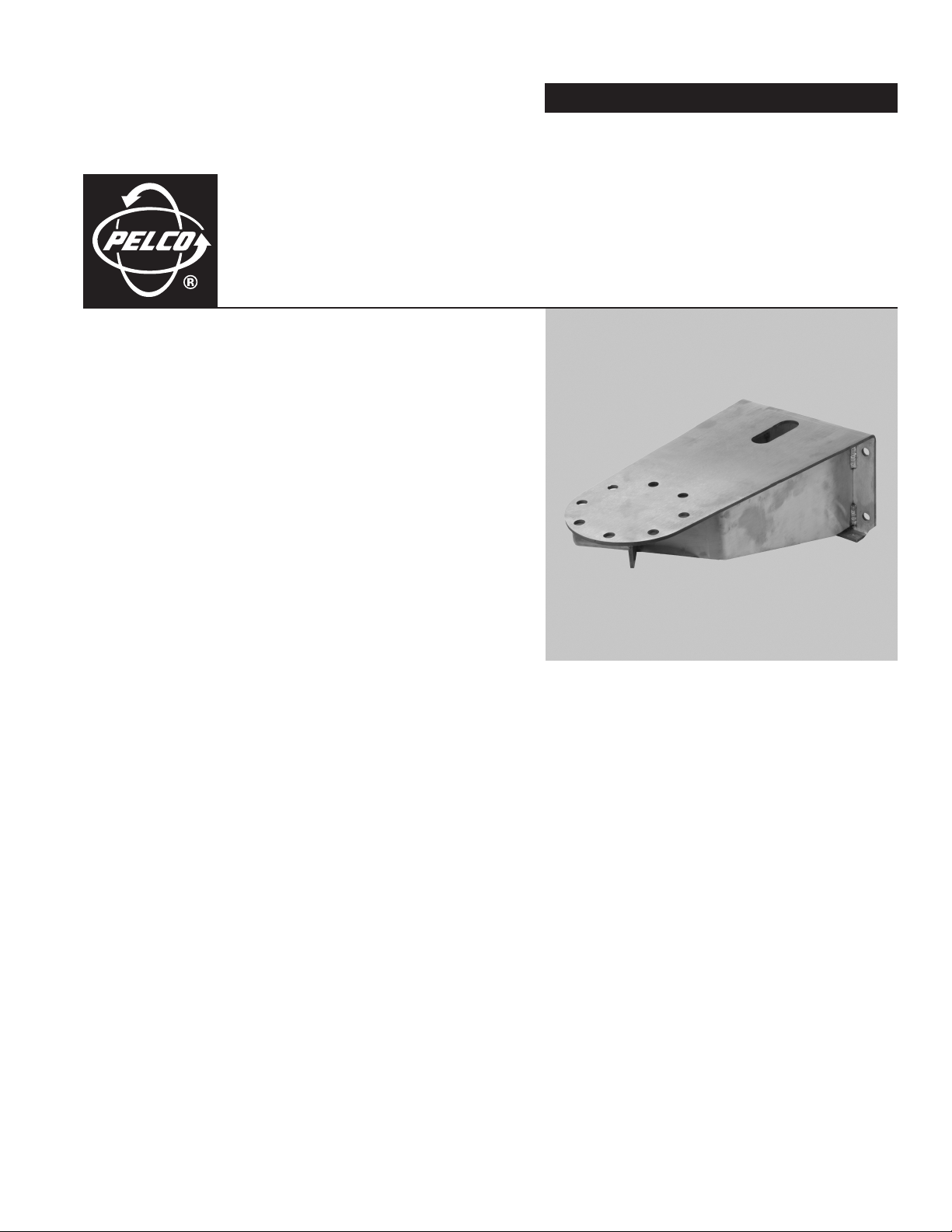
ExSite
™
Series Mounts
WXM100, CMXM100,
PAXM100, and PXM100
INSTALLATION
C2216M (5/05)
WXM100
Page 2

Page 3
C2216M (5/05) 3
Important Safety Instructions
1. Read these instructions.
2. Keep these instructions.
3. Heed all warnings.
4. Follow all instructions.
5. Only use attachments/accessories specified by the manufacturer.
6. Use only with the cart, stand, tripod, bracket, or table specified by the manufacturer, or sold with the apparatus. When a cart is used, use
caution when moving the cart/apparatus combination to avoid injury from tip-over.
7. Installation should be done only by qualified personnel and conform to all local codes.
8. Use only installation methods and materials capable of supporting four times the maximum specified load.
9. Use stainless steel hardware to fasten the mount to outdoor surfaces.
CAUTION: These servicing instructions are for use by qualified service personnel only. To reduce the risk of electric shock do not perform any
servicing other that contained in the operating instructions unless you are qualified to do so.
10. Only use replacement parts recommended by Pelco.
The product and/or manual may bear the following marks:
WARNING: This symbol indicates that dangerous voltage constituting a
risk of electric shock is present within this unit.
This symbol indicates that there are important operating and maintenance
instructions in the literature accompanying this unit.
CAUTION:
RISK OF ELECTRIC SHOCK.
DO NOT OPEN.
Page 4

4 C2216M (5/05)
Description
This manual contains the installation instructions for the following ExSite
™
Series mounts:
WXM100 Wall mount designed to mount the ExSite
Series system directly to a load-bearing vertical surface.
CMXM100 Corner adapter for use with the WXM100 to mount an ExSite Series system to the corner of a structure.
PAXM100 Pole adapter for use with the WXM100 to mount a system to a horizontal pole.
PXM100 Pedestal mount designed to mount an ExSite Series system directly to a horizontal surface in either an upright or inverted
position.
*Recommended strength of concrete is 3,600 psi or 25 Mpa.
**Minimum of 1/8-inch wall.
Model Supplied Hardware Mounting Surface Recommended Hardware
WXM100 None
Solid Concrete*
Five 3/8-16 x 1-9/16-inch long stainless steel drop-in anchors and five 3/8-16 x 1.0-inch
thread length, stainless steel hex head bolts with stainless steel lock washers
Steel I Beam**
Five 3/8-16 x 1.0-inch thread length, stainless steel hex head bolts with stainless
steel lock washers and 3/8-16 stainless steel nuts
CMXM100
Five 3/8-16 x 1.0-inch
thread length, stainless
steel hex head bolts with
lock washers to attach
the adapter to the
WXM100 wall mount
Solid Concrete*
Six 1/2-13 x 2-inch stainless steel drop-in anchors and six 1/2-13 x 1.0-inch thread
length, stainless steel hex head bolts with stainless steel lock washers
Steel I Beam**
Six 1/2-13 x 1.0-inch thread length, stainless steel hex head bolts with stainless
steel lock washers and 1/2-13 stainless steel nuts
PAXM100
Four 5/8-inch wide x
40-inch (101.6 cm) long
stainless steel straps to
attach the adapter to a
pole
Five 3/8-16 x 1.0-inch
thread length, stainless
steel hex head bolts with
lock washers to attach
the adapter to the
WXM100 wall mount
Steel pole with a
diameter between
4 and 9 inches
(10.16 to 22.86 cm)
Supplied
PXM100 None
Solid Concrete*
Five 3/8-16 x 1-9/16-inch long stainless steel drop-in anchors and five 3/8-16 x 1.0-inch
thread length, stainless steel hex head bolts with stainless steel lock washers
Steel I Beam**
Five 3/8-16 x 1.0-inch thread length, stainless steel hex head bolts with stainless
steel lock washers and 3/8-16 stainless steel nuts
Page 5

C2216M (5/05) 5
Installation
WXM100 WALL MOUNT
To install the WXM100 refer to Figure 1 and perform the following steps:
1. Determine the mounting location. The mounting surface should be able to support four times the combined weight of the mount and ExSite
system.
2. Using the flanged end of the wall mount as a template, mark the five fastener hole positions onto the mounting surface. Set the WXM100
mount to the side and prepare the holes for the fasteners.
3. Position the wall mount over the mounting holes. Attach the mount to the mounting surface with the appropriate hardware (not supplied).
4. Secure the ExSite power module to the WXM100 with the 8 mm Allen wrench and four M10 x 16 mm stainless steel bolts supplied with the
power module. Tighten the bolts to 25 to 27 ft-lb (34 to 37 Nm).
5. Complete the ExSite system installation following the instructions supplied with the equipment.
Figure 1. WXM100 Installation
Page 6

6 C2216M (5/05)
CMXM100 CORNER MOUNT ADAPTER
To install the CMXM100 refer to Figure 2 and perform the following steps:
1. Attach the corner mount adapter to the mounting surface with the appropriate hardware (not supplied). The mounting surface should be
able to support four times the combined weight of the corner mount adapter, WXM100 mount, and ExSite system.
2. Attach the WXM100 wall mount to the corner mount adapter with the supplied five 3/8-16 x 1.0-inch thread length, stainless steel hex
head bolts and stainless steel lock washers.
3. Secure the ExSite power module to the WXM100 with the 8 mm Allen wrench and four M10 x 16 mm stainless steel bolts supplied with the
power module. Tighten the bolts to 25 to 27 ft-lb (34 to 37 Nm).
4. Complete the ExSite system installation following the instructions supplied with the equipment.
Figure 2. CMXM100 Installation
Page 7

C2216M (5/05) 7
PAXM100 POLE MOUNT ADAPTER
Install the PAXM100 to a steel pole with a diameter between 4 and 9 inches (10.16 to 22.86 cm). Refer to Figure 3 and perform the following
steps:
1. Attach the pole mount adapter to the pole with the four stainless steel straps (supplied). Tighten the clamps of the straps to 6.25 to
7.5 ft-lb (8.5 to 10.2 Nm).
2. Attach the WXM100 wall mount to the pole mount adapter with the supplied five 3/8-16 x 1.0-inch thread length, stainless steel hex head
bolts and stainless steel lock washers.
3. Secure the ExSite power module to the WXM100 with the 8 mm Allen wrench and four M10 x 16 mm stainless steel bolts supplied with the
power module. Tighten the bolts to 25 to 27 ft-lb (34 to 37 Nm).
4. Complete the ExSite system installation following the instructions supplied with the equipment.
Figure 3. PAXM100 Installation
Page 8

8 C2216M (5/05)
PXM100 PEDESTAL MOUNT
The PXM100 mount is designed to make the installation and removal of the ExSite power module quick and easy. To install the PXM100 refer to
Figure 4 and perform the following steps:
1. Attach the power module of the ExSite system to the pedestal mount with four M10 x 16 mm stainless steel bolts and lock washers
supplied with the power module (refer to Figure 4). Tighten the bolts to 25 to 27 ft-lb (34 to 37 Nm).
Figure 4. Attach Power Module to PXM100
2. Attach the pedestal mount to the mounting surface with the appropriate hardware (not supplied).
3. Complete the ExSite system installation following the instructions supplied with the equipment.
NOTE: Figure 4 shows the power module
being installed on a PXM100 pedestal mount
(not supplied).
Page 9

C2216M (5/05) 9
Specifications
Construction
Mounts Electro-polished 304 stainless steel
PAXM100 Mounting Straps 316 stainless steel
Maximum Load
WXM100 73 lb (33 kg)
CMXM100 85 lb (38.50 kg)
PAXM100 88 lb (40 kg)
PXM100 79 lb (35.83 kg)
Weight
WXM100 12.4 lb (5.62 kg)
CMXM100 7.6 lb (3.45 kg)
PAXM100 9.2 lb (4.17 kg)
PXM100 1.3 lb (0.60 kg)
WXM100
CMXM100
14.9
(37.8)
8.15
(20.7)
5.5
(14.1)
5X THREADED HOLES
FOR 3/8-16 SS BOLTS
Ø
9.25
(23.5)
8.00
(20.32)
3.50
(8.89)
PAXM100
8X 0.433 THRU EQ SP
Ø
ON A 4.75 B.C.
14.95
(37.97)
7.00
(17.78)
4X 0.500 THRU EQ SP
Ø
ON A 7.25 B.C.
10.00
(25.4)
5X Ø 0.422
5.74
(14.58)
3.5
(8.9)
8.50
(21.6)
PXM100
4X 0.433 THRU
Ø
EQ SP ON A
4.75 B.C
Ø
4X 0.433 THRU
EQ SP ON A
7.00 B.C
Ø
4X 0.413 THRU EQ SP
Ø
ON A 7.00 B.C
Ø
8.00
(20.3)
4X 0.433 THRU
Ø
Ø 6.25
(15.87)
0.60
(0.15)
Ø 5.68
(14.42)
Ø
EQ SP ON A
7.25 B.C
Ø
0.538
(1.37)
3.28
(8.33)
NOTE: VALUES IN PARENTHESES ARE CENTIMETERS;
8.50
(21.6)
3.5
ALL OTHERS ARE INCHES.
Page 10

10 C2216M (5/05)
Page 11

PRODUCT WARRANTY AND RETURN INFORMATION
WARRANTY
Pelco will repair or replace, without charge, any merchandise proved defective in material or
workmanship for a period of one year after the date of shipment.
Exceptions to this warranty are as noted below:
• Five years on FT/FR8000 Series fiber optic products.
• Three years on Genex
®
Series products (multiplexers, server, and keyboard).
• Three years on Camclosure
®
and fixed camera models, except the CC3701H-2,
CC3701H-2X, CC3751H-2, CC3651H-2X, MC3651H-2, and MC3651H-2X camera models,
which have a five-year warranty.
•Two years on standard motorized or fixed focal length lenses.
•Two years on Legacy
®
, CM6700/CM6800/CM9700 Series matrix, and DF5/DF8 Series
fixed dome products.
•Two years on Spectra
®
, Esprit
®
, ExSite
™
, and PS20 scanners, including when used in
continuous motion applications.
•Two years on Esprit
®
and WW5700 Series window wiper (excluding wiper blades).
• Eighteen months on DX Series digital video recorders, NVR300 Series network video
recorders, and Endura
™
Series distributed network-based video products.
• One year (except video heads) on video cassette recorders (VCRs). Video heads will be
covered for a period of six months.
• Six months on all pan and tilts, scanners or preset lenses used in continuous motion
applications (that is, preset scan, tour and auto scan modes).
Pelco will warrant all replacement parts and repairs for 90 days from the date of Pelco
shipment. All goods requiring warranty repair shall be sent freight prepaid to Pelco, Clovis,
California. Repairs made necessary by reason of misuse, alteration, normal wear, or accident
are not covered under this warranty.
Pelco assumes no risk and shall be subject to no liability for damages or loss resulting from
the specific use or application made of the Products. Pelco’s liability for any claim, whether
based on breach of contract, negligence, infringement of any rights of any party or product
liability, relating to the Products shall not exceed the price paid by the Dealer to Pelco for
such Products. In no event will Pelco be liable for any special, incidental or consequential
damages (including loss of use, loss of profit and claims of third parties) however caused,
whether by the negligence of Pelco or otherwise.
The above warranty provides the Dealer with specific legal rights. The Dealer may also have
additional rights, which are subject to variation from state to state.
If a warranty repair is required, the Dealer must contact Pelco at (800) 289-9100 or
(559) 292-1981 to obtain a Repair Authorization number (RA), and provide the following
information:
1. Model and serial number
2. Date of shipment, P.O. number, Sales Order number, or Pelco invoice number
3. Details of the defect or problem
If there is a dispute regarding the warranty of a product which does not fall under the
warranty conditions stated above, please include a written explanation with the product
when returned.
Method of return shipment shall be the same or equal to the method by which the item was
received by Pelco.
RETURNS
In order to expedite parts returned to the factory for repair or credit, please call the factory at
(800) 289-9100 or (559) 292-1981 to obtain an authorization number (CA number if returned
for credit, and RA number if returned for repair).
All merchandise returned for credit may be subject to a 20% restocking and refurbishing
charge.
Goods returned for repair or credit should be clearly identified with the assigned CA or RA
number and freight should be prepaid. Ship to the appropriate address below.
If you are located within the continental U.S., Alaska, Hawaii or Puerto Rico, send goods to:
Service Department
Pelco
3500 Pelco Way
Clovis, CA 93612-5699
If you are located outside the continental U.S., Alaska, Hawaii or Puerto Rico and are
instructed to return goods to the USA, you may do one of the following:
If the goods are to be sent by a COURIER SERVICE, send the goods to:
Pelco
3500 Pelco Way
Clovis, CA 93612-5699 USA
If the goods are to be sent by a FREIGHT FORWARDER, send the goods to:
Pelco c/o Expeditors
473 Eccles Avenue
South San Francisco, CA 94080 USA
Phone: 650-737-1700
Fax: 650-737-0933
REVISION HISTORY
Manual # Date Comments
C2216M 5/05 Original version.
Pelco, the Pelco logo, Camclosure, Esprit, Genex, Legacy, and Spectra are registered trademarks of Pelco. ©Copyright 2005, Pelco. All rights reserved.
Endura and ExSite are trademarks of Pelco.
Page 12

Worldwide Headquarters
3500 Pelco Way
Clovis, California 93612 USA
USA & Canada
Tel: 800/289-9100
Fax: 800/289-9150
International
Tel: 1-559/292-1981
Fax: 1-559/348-1120
www.pelco.com
ISO
United States | Canada | United Kingdom | The Netherlands | Singapore | Spain | Scandinavia | France | Middle East
9001
 Loading...