

Page 1
PelcoVision™ PV1000 Series
Quick Start Guide
INTRODUCTION
The purpose of this document is to provide the experienced CCTV/electronics user a logical quick start to the PelcoVision™ Phone
Line Transmission System. This document will detail the minimum steps necessary to transmit and receive video using the
PelcoVision™ system. For detailed installation, programming and operating instructions refer to the PelcoVision™ I/O Manual
(C1913M).
Recommendations
PSTN Models: Pelco does not recommend using a PBX phone connection for the PV110 modem due to the possibility of
bandwidth limitations or digital voltages. If at all possible, use a true analog, FAX grade phone connection.
ISDN Models: Pelco recommends using the AT&T 5ESS switch type using the Multipoint/Initializing switch version,
configured for the Adtrans Express 3000. However, the ISDN switch type and switch is not critical as long as it supports
Asynchronous Bonding.
SETTING UP THE RECEIVER TO CALL A TRANSMITTER
This section will provide the minimum details necessary to establish a phone line connection between the PV1016R(N) and the
PelcoVision™ demonstration site (PSTN telephone number 1-888-294-1560) or another known PelcoVision™ Transmitter (see
Setting Up a Transmitter to Receive a Call).
Hardware Setup
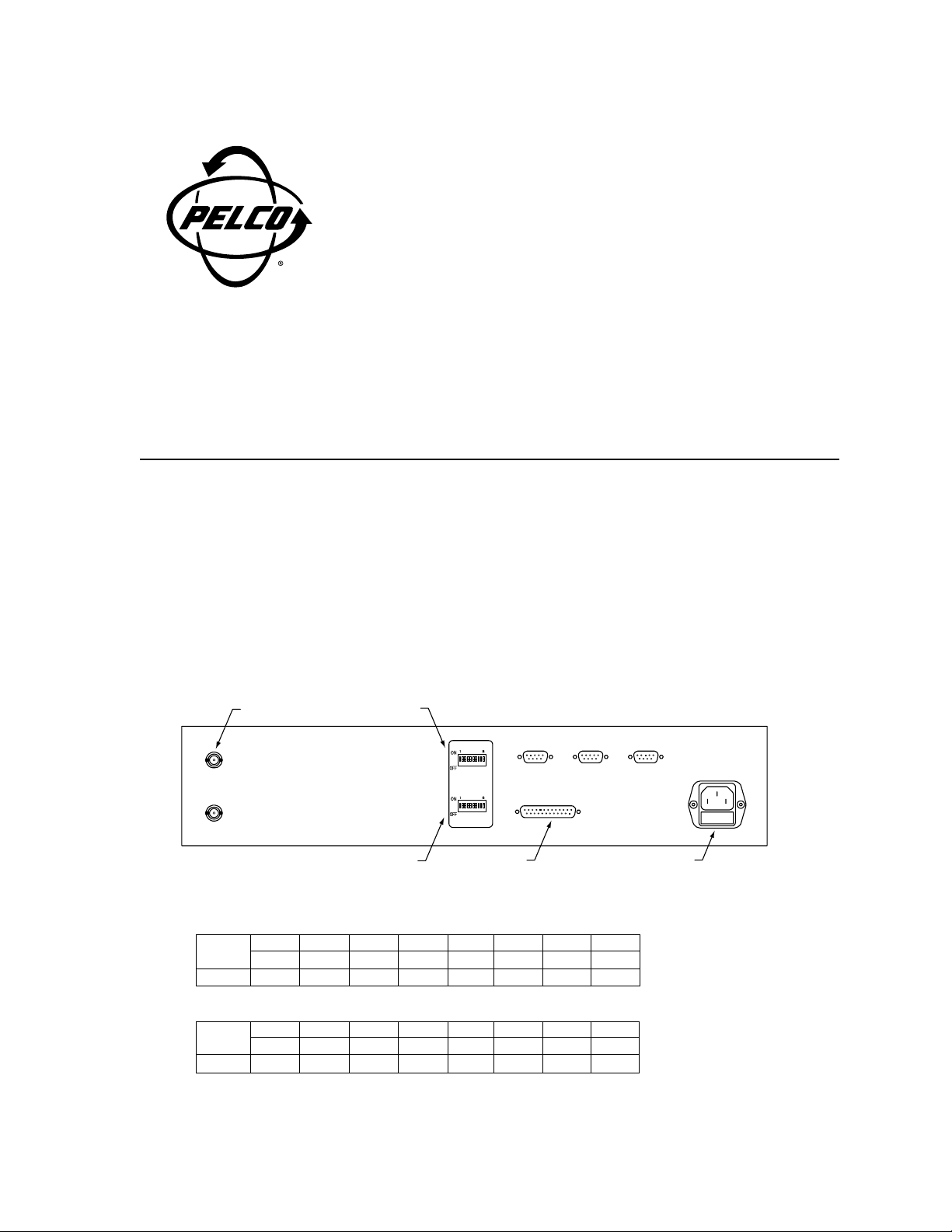
■ Remove the DIP switch cover from the rear of the Receiver and set SW 1 and SW 2 according to model. Refer to Figure 1
when setting DIP switches and making cable connections to the PV1016R.
MONITOR OUTPUT
SW 2
REAR
MONITOR 1
MONITOR 2
SW 1
SW2
SW1
MODEM PORT
MODEM
COM 2COM 1
KEYBOARD
AC POWER
Figure 1. PV1016R Rear Panel
PV1016R (with PV110 Modem)
12345678
SW 1 ON ON OFF OFF OFF OFF OFF OFF
SW 2 ON OFF OFF OFF N/A N/A N/A N/A
PV1016RN (with PV120 ISDN Terminal Adapter)*
12345678
SW 1 ON ON OFF OFF OFF OFF OFF OFF
SW 2 ON OFF OFF OFF N/A N/A N/A N/A
*Program the PV120 in accordance with the instructions included in the PV120 package prior to connecting it to the Receiver. It must
match the configuration of the PV120 used for the Transmitter. DIP switch settings for the PV120 are correct out of the box.
C1913M-QS (9/99)
Page 2
■ Set the DIP switches on the rear of the PV110 modem according to the table below.
PV110 Modem DIP Switch Settings
12345678
ON ON OFF OFF ON ON OFF OFF
■ Connect the modem or terminal adapter to the Receiver using the supplied cable.
■ Connect the Receiver to an approved power source.
■ Connect a monitor to either monitor output.
■ Connect phone line(s) and power supply to the modem or terminal adapter.
Programming a Transmitter Number for Call-up
Switch power ON to the Modem/Terminal Adapter first, then turn on the Receiver. The Modem/Terminal Adapter will take a moment
to “handshake” with the Receiver before being ready to call a Transmitter. If Receiver and Modem/Terminal Adapter will not
successfully handshake, confirm DIP switch settings and/or programming (PV120) are correct.
NOTE
If Receiver and Modem/Terminal Adapter will not handshake after power-up, cycle power and observe the start-up message
on the monitor. The PV1016R with the PV110 will display U.S. ROBOTICS DTE SPEED 38,400 as the modem type and
speed. The PV1016RN with the PV120 will display PREINITIALIZED DTE SPEED 115,200 as the modem type and
speed. If the displayed message is incorrect, re-check the DIP switch settings.
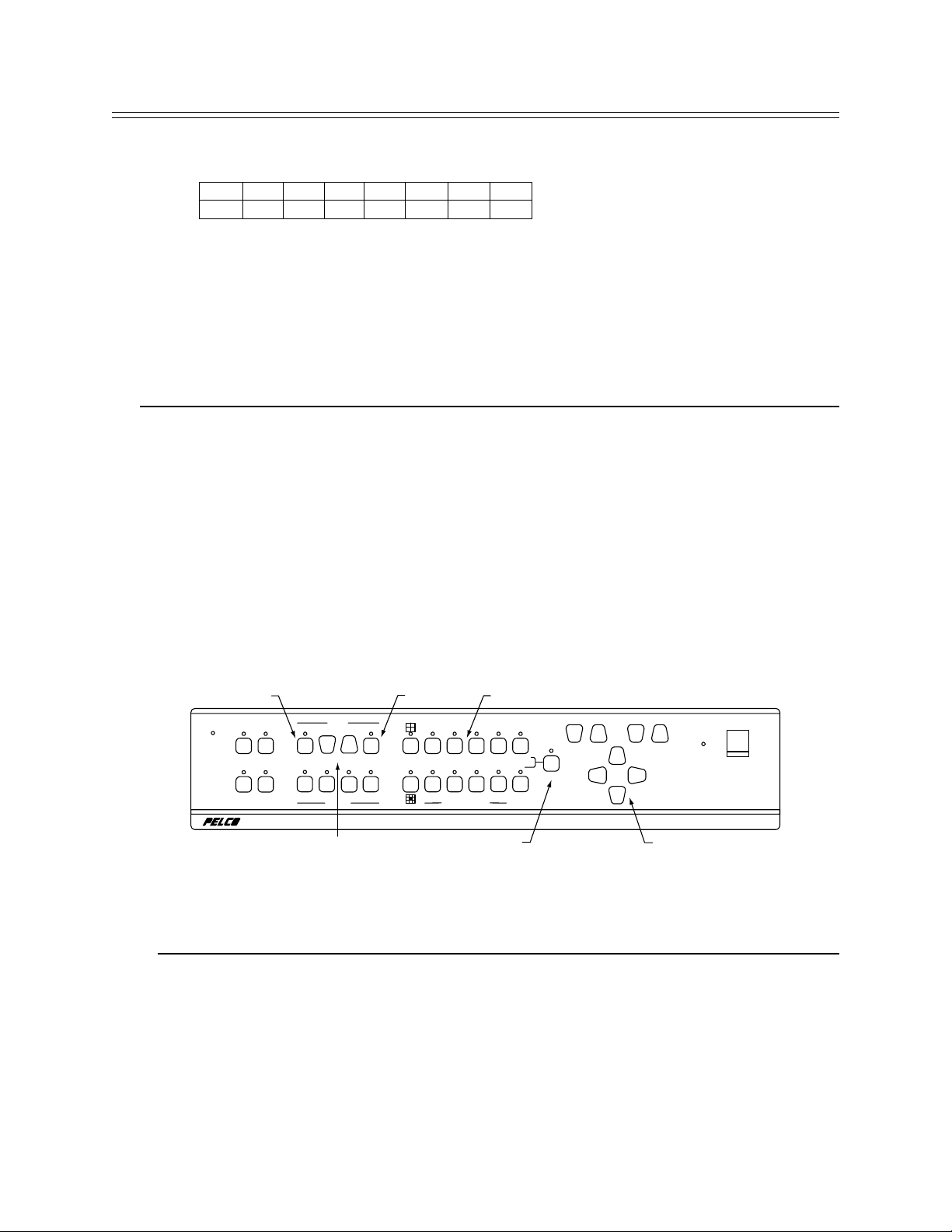
Refer to Figure 2 during the instructions that follow.
■ From the Receiver front panel, press the PROG (program) key to display the Receiver Status dialog box on the monitor
display.
■ Enter 1234 (default pass code) to display the Programming dialog box.
■ Using the PAN/TILT keys, move the highlight to Receiver and press the ENTER key to display the main Receiver Program-
ming dialog box.
■ Using the PAN/TILT keys, highlight Director y in the Receiver Programming menu, then press the ENTER key to display the
Telephone Directory list. The left side of the Telephone Directory is for entering site names; the right side for entering
telephone numbers.
■ Use the PAN/TILT keys to move around within the Directory menu.
■ Use the SCROLL keys to increment/decrement through the allowable character set for each character entry.
■ Enter the Site Name (optional) and phone number of the Transmitter you wish to connect to. Don’t forget to include area
code and/or any other access numbers, as necessary.
DIR
LINE
12
34
AUXILIARY
PHONE
NUMBER
DIR SCROLL ENTER
VERIFY
NEW HIGH WNDO FREEZ
DISPLAY
ENTER
0
1
12
56
56
CAMERA - PRESET
DIAL
SCROLL
NUMBER PAD (1234)
23
4
4
3
789
7 8 A/B
PROG
PRESETDIR
MODEM
FRONT
FOCUSZOOM
POWER
PROG
PAN / TILT
RECEIVER
PAN/TILT
Figure 2. Front Panel
Pelco has made available a toll-free PSTN demonstration number for 24-hour call-up. An ISDN site is available by appointment.
Dealers may call Pelco at 1-800-289-9100 to obtain the ISDN demonstration number.
Site Phone Number
Toll-free PSTN demonstration site 1-888-294-1560
■ To return to the PelcoVision™ main screen after entering Transmitter phone number(s), press ENTER, move the highlight to
Save Changes (you must save the changes), press ENTER, move to Exit, press ENTER, and finally, move to Exit again and
press ENTER.
Dialing a Transmitter Phone Number
Press the DIR key (from the PelcoVision™ screen) to display the Telephone directory. Use the NUMBER up/down keys to highlight
the entry to be dialed and press DIAL. The Receiver will dial the number and attempt a connection. If successful, the type of
connection and baud rate will be displayed on the monitor. If unsuccessful, a reason code will be displayed. See Troubleshooting or
section 7.0 in the PelcoVision™ I/O Manual (C1913M).
Page 3

SETTING UP A TRANSMITTER TO RECEIVE A CALL
This section details the minimum steps necessary to set up a Transmitter for transmission of video to a Receiver. Refer to Figure 3
when setting DIP switches and making cable connections to the PV1016T.
PV1016T
SW 1
SW 2
REAR
B
HILOB
12
LOOPHILOBLOOPHILOBLOOPHILOBLOOP
A
CAMERA INPUT A1
3456
HILOB
LOOPHILOBLOOPHILOBLOOPHILOBLOOP
78
SW1 SW2
MONITOR
MODEM PORT AC POWER
COM 2COM 1
MODEM ALARM
KEYBOARD
Figure 3. PV1016T Rear Panel
Hardware Setup
■ Remove the DIP switch cover from the rear of the Transmitter and set SW 1 and SW 2 according to the appropriate table.
PV1016T Transmitter with PV110 Modem
12345678
SW 1 ON ON OFF OFF ON ON OFF OFF
SW 2 ON OFF OFF OFF OFF OFF OFF OFF
PV1016TN Transmitter with PV120 Terminal Adapter*
12345678
SW 1 ON ON OFF ON ON ON OFF OFF
SW 2 ON OFF OFF OFF OFF OFF OFF OFF
PV1004T Transmitter with PV110 Modem
12345678910
SW 1 ON ON ON ON N/A N/A N/A N/A N/A N/A
SW 2 ON OFF OFF OFF ON ON OFF OFF OFF ON
PV1004T Transmitter with PV120 Terminal Adapter*
12345678910
SW 1 ON ON ON ON N/A N/A N/A N/A N/A N/A
SW 2 ON ON OFF ON ON ON OFF OFF OFF ON
*Program the PV120 in accordance with the Instruction Sheet (C1918M) included in the PV120 package prior to connecting it to the
Transmitter. It m ust match the configuration of the PV120 used for the Receiver. DIP switch settings for the PV120 are correct out of the
box.
■ Set the DIP switches on the rear of the PV110 modem according to the table below.
PV110 Modem DIP Switch Settings
1 234567 8
ON ON OFF OFF ON ON OFF OFF
■ Connect the modem or terminal adapter to the Transmitter using the supplied cable.
■ Connect the Transmitter to an approved power source.
■ Connect a camera to camera input A1 on the rear of the Transmitter.
■ Connect phone line(s) and power supply to the modem or terminal adapter.
■ Switch power ON to the Modem/Terminal Adapter first, then turn on the Transmitter. The Modem/Terminal Adapter will take
a moment to “handshake” with the Transmitter. If Transmitter and Modem/Ter minal Adapter will not successfully handshake,
confirm programming and/or DIP switch settings. When the handshake is complete the Transmitter is ready to transmit video.
BACK-TO-BACK RECEIVER AND TRANSMITTER SETUP
This section will detail the minimum steps necessary to establish a back-to-back, demonstration mode, connection between a
PelcoVision™ Receiver and a PelcoVision™ Transmitter. This setup does not require modems or terminal adapters.
Page 4

Back-to-back operation requires a “full handshake” null modem connection between Transmitter and Receiver. A null modem adapter
is available at most electronics stores (check gender requirements for the adapter) or create your own null modem by wiring two
female 25-pin D-sub connectors according to Figure 22 in the PelcoVision™ I/O Manual (C1913M).
PV1004T REARAC POWER
CAMERAS
1234
SW1 SW2 MODEM ALARM COM 1 COM 2
CAMERA INPUT 1 SW 1
SW 2 MODEM PORT
Figure 4. PV1004T Rear Panel
Hardware Setup
■ Remove the DIP switch access panels from the rear of the Transmitter and Receiver and set switches according to the
appropriate table.
Receiver, PV1016R models
SW 1 ON ON OFF OFF OFF OFF OFF OFF
SW 2 ON OFF OFF OFF N/A N/A N/A N/A
Transmitter, PV1016T models
SW 1 ON ON OFF OFF OFF OFF OFF OFF
SW 2 ON OFF OFF OFF OFF OFF OFF OFF
Transmitter, PV1004T models
SW 1 ON ON ON ON N/A N/A N/A N/A N/A N/A
SW 2 ON OFF OFF OFF OFF OFF OFF OFF OFF ON
■ Connect a monitor to the Receiver monitor output.
■ Connect at least one camera to a Transmitter camera input.
■ Connect Receiver and Transmitter together using a null modem cable.
■ Plug Receiver and Transmitter into a suitable electrical outlet.
■ Switch power ON to the Receiver and Transmitter. If they are configured and connected correctly, the Receiver should begin
to receive video from the Transmitter.
■ This will create a connection at 38.4 kbps.
12345678
12345678
12345678910
TROUBLESHOOTING
PROBLEM POSSIBLE CAUSE FIX
■ Cannot access the telephone Receiver is configured in the Leased Set the DIP switches on the back of the
directory to call Transmitter site. Line mode. Receiver to the correct modem setting.
■ Selected number does not dial Telephone number is programmed into Ensure the telephone number is programmed
at all. the Receiver incorrectly. on the right hand side of the Telephone
■ PelcoVision™ Receiver will not Modem or Terminal Adapter is faulty, Set the DIP switch settings on the back of the
initialize, seems to restart Receiver is not programmed correctly, Receiver to the correct modem setting.
over and over. or modem cable is bad. Check modem power and data connections.
■ ISDN Receiver cannot call the Terminal Adapter is not configured Ensure the Receiver site terminal adapter is
ISDN Transmitter or the correctly. Bad modem cable. bonded exactly the same as the Transmitter
PelcoVision™ ISDN site terminal adapter. Refer to PelcoVision™
demonstration site. I/O Manual (C1913M).
Directory box.
Check phone line for possible access codes .
PBX systems usually require a 9 dialed first.
Check for dial tone, or if using ISDN, chec k for
a steady green LS light on the Terminal Adapter.
Ensure that verbal result codes are enabled
by the modem DIP switches.
Try using another modem.
 Loading...