

PT780 Legacy® Series
Pan/Tilts
Installation/
Operation Manual
C342M-D (8/05)
Pelco • 3500 Pelco Way, Clovis • CA 93612-5699 USA • www.pelco.com
In North America and Canada: Tel (800) 289-9100 or FAX (800) 289-9150
International Customers: Tel (1-559) 292-1981 or FAX (1-559) 348-1120

CONTENTS
Section Page
1.0 GENERAL .................................................................................................. 5
1.1 IMPORTANT SAFEGUARDS AND WARNINGS ............................... 5
2.0 DESCRIPTION .......................................................................................... 6
2.1 MODELS ............................................................................................6
3.0 INSTALLATION .......................................................................................... 7
3.1 MOUNTING ....................................................................................... 7
3.2 PAN AND TILT LIMIT STOP ADJUSTMENTS ................................... 8
3.3 ENCLOSURE INSTALLATION ......................................................... 10
3.4 ELECTRICAL INSTALLATION .......................................................... 10
3.4.1 LRD41 Series Legacy® Receiver/Drivers .............................. 10
3.4.2 All Control Equipment Except LRD41 Series
Legacy® Receiver/Drivers .....................................................10
4.0 OPERATION .............................................................................................19
5.0 MAINTENANCE ........................................................................................20
5.1 SERVICE MANUAL .......................................................................... 21
6.0 SPECIFICATIONS ....................................................................................22
7.0 WARRANTY AND RETURN INFORMATION ........................................... 24
2 Pelco Manual C342M-D (8/05)

LIST OF ILLUSTRATIONS
Figure Page
1 Removing the Screws ........................................................................8
2 Releasing the Covers ........................................................................ 8
3 Removing the Covers ........................................................................ 8
4 Hooking Cover Halves ....................................................................... 8
5 Tilt Limit Adjustment ...........................................................................9
6 Pan Limit Adjustment .........................................................................9
7 Replacing the Cover Halves .............................................................. 9
8 Securing the Cover Halves ................................................................ 9
9 Connector Assembly ......................................................................... 11
10 Wiper On/Off Connection .................................................................. 12
11 Pan/Tilt Adjustments ......................................................................... 20
12 PT780 Series Dimension Drawing ....................................................23
LIST OF TABLES
Table Page
A-1 37-Position Connector Pin Designations for Pan/Tilts with
EH4700L and EH5700L Enclosures .................................................13
A-2 37-Position Connector Pin Designations for Pan/Tilts with
EH8106L Enclosures ........................................................................ 14
B Requirements to Wire Power to Pan and Tilt Motors ........................15
C Maximum Cable Distances Using RB24 or RB115 Relay Boxes...... 16
D Requirements to Wire Power to Camera Enclosure ......................... 17
E Requirements to Wire Power for Optional Heater Blanket ............... 17
F 24 VAC Wiring Distances Chart ........................................................18
REVISION HISTORY
Manual Date Comments
C342M 1991 Original version.
C342M-A 4/96 Consolidated C344M and C345M manuals into C342M-A
4/96 Updated wiring instructions for EH8106L enclosures.
C342M-B 6/97 Put into new format. Revised exploded assembly
manual. Revised installation instructions. Created
manual history and updated to new manual style.
diagrams in Figures 12, 13, 14 and 15 to show
movement of the wire clamp and grommet from the side
to the bottom of the pan spindle per ECO #96-352. Pan
spindle nut (part # 9004004COMP) replaced by snap
ring (part # 80010019) per ECO #97-194. Figure 4
revised.
C342M-C 11/98 Revised Section 5.0, Maintenance. Moved Section 6.0,
C342M-D 8/05 Added ratings per ECO 05-10441. Added WEEE
Exploded Assembly Diagrams, to new service manual
(C342SM). Repaginated manual.
statement.
Pelco Manual C342M-D (8/05) 3

(This page intentionally left blank.)
4 Pelco Manual C342M-D (8/05)
1.0 GENERAL
1.1 IMPORTANT SAFEGUARDS AND WARNINGS
Prior to installation and use of this product, the following WARNINGS should be
observed.
1. Installation and servicing should only be done by qualified service personnel
and conform to all local codes.
2. The weight of the camera/lens and enclosure shall not exceed 40 lb (18.14 kg)
with 12VDC pan/tilts or 52 lb (23.59 kg) with 24 VAC or 120 VAC pan/tilts.
3. Only use replacement parts recommended by Pelco.
4. After replacement/repair of this unit’s electrical components, conduct a resistance measurement between line and exposed parts to verify the exposed
parts have not been connected to line circuitry.
5. The installation method and materials should be capable of supporting four
times the weight of the enclosure, pan/tilt, camera and lens combination.
The product and/or product manual may bear the following
marks:
This symbol indicates that dangerous voltage constituting a
risk of electric shock is present within this unit.
This symbol indicates that there are important operating and
maintenance instructions in the literature accompanying this
unit.
CAUTION:
RISK OF
ELECTRIC SHOCK.
DO NOT OPEN.
TO REDUCE THE RISK OF ELECTRICAL SHOCK,
DO NOT REMOVE COVER. NO USER-
SERVICEABLE PARTS INSIDE. REFER SERVICING
TO QUALIFIED SERVICE PERSONNEL.
CAUTION:
Please thoroughly familiarize yourself with the information
in this manual prior to installation and operation.
Pelco Manual C342M-D (8/05) 5

2.0 DESCRIPTION
The PT780 Legacy® Series pan/tilt units are designed for medium, indoor/outdoor
use.
Only Legacy Series enclosures can be mounted on the pan/tilt units. These enclosures are the EH4700L and EH5700L environmental enclosures and the EH8106L
pressurized enclosure. Pelco’s RediLINKTM connector makes it simple and quick
for you to install an enclosure. The weight of the enclosure with camera and lens
must not exceed 40 pounds (18.14 kg) with the 12 VDC pan/tilt units or 52 pounds
(23.56 kg) with the 24 VAC or 120 VAC pan/tilt units.
You can easily remove the clamshell covers from the sides of the pan/tilt units to
access all internal parts without having to remove the camera enclosure. This makes
it easy to service the units and to adjust the pan and tilt limit stops.
2.1 MODELS
The PT780 Series consists of the following models:
PT780P Heavy-duty, indoor/outdoor pan/tilt, 120 VAC.
PT780P/PP PT780P with preset positioning capabilities.
PT780SL PT780P with 360° pan rotation.
PT780SL/PP PT780SL with preset positioning capabilities.
PT780-VS Heavy-duty, indoor/outdoor, variable-speed pan/tilt, 12
PT780-VS/PP PT780VS with preset positioning capabilities.
PT780-VSSL PT780VS with 360° pan rotation.
PT780-VSSL/PP PT780-VSSL with preset positioning capabilities.
PT780-24P Heavy-duty, indoor/outdoor pan/tilt, 24 VAC.
PT780-24P/PP PT780-24P with preset positioning capabilities.
PT780-24SL PT780-24P with 360° pan rotation.
PT780-24SL/PP PT780-24SL with preset positioning capabilities.
VDC.
6 Pelco Manual C342M-D (8/05)

3.1 MOUNTING
3.0 INSTALLATION
NOTE:
To insure proper wiring and
operation of your equipment, it is recommended that you test the pan/tilt
unit and associated equipment in your
facility before installing it in the field.
Refer to Sections 3.2 through 3.4.
CAUTION:
The PT780
pan/tilt units are designed
for upright or inverted (base
up) operation. Never mount
the pan/tilt horizontally.
NOTE:
If you mount your pan/tilt unit
in the inverted position, you must install a rain cover (part number
90010018).
Attach the pan/tilt unit to a wall or ceiling mount. Follow the instructions that are
provided with the mount. Make sure the mounting surface and the selected mount
can support four times the combined weight of the pan/tilt unit and the camera
enclosure (including the camera and lens). The pan/tilt unit weighs approximately
21.5 pounds (9.68 kg). Refer to the manuals for your enclosure, camera, and lens
for the weights of those items.
Pelco Manual C342M-D (8/05) 7
3.2 PAN AND TILT LIMIT STOP ADJUSTMENTS
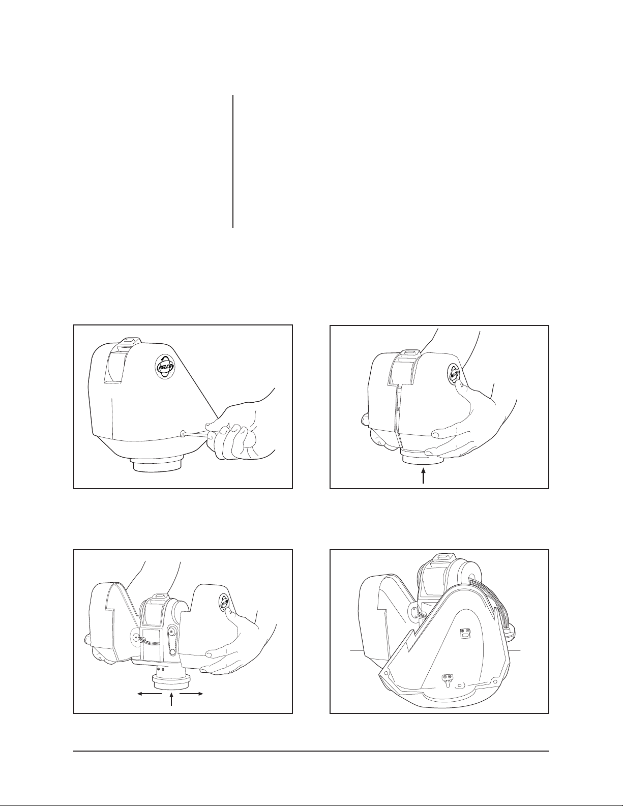
1. Remove the covers.
a. Refer to Figure 1 and remove the Phillips screw on each side of the pan/
tilt unit.
b. Refer to Figure 2 and place your hands under the cover halves. Exert a
strong, upward force to release the covers from their internal latching
devices.
c. Refer to Figure 3 and pull the cover halves away from the pan/tilt unit.
d. Set the covers down or hang them by the eyelets inside the covers (refer
to Figure 4). The wire and hook on which to hang the covers is not provided.
Figure 1. Removing the Screws
Figure 3. Removing the Covers
Figure 2. Releasing the Covers
Figure 4. Hooking Cover Halves
8 Pelco Manual C342M-D (8/05)

CAUTION:
the tilt limit stops.
NOTE:
SL models do not have pan
limit stops.
Never remove
2. Adjust the tilt limit stops.
Refer to Figure 5 for the location of the tilt limit stops. The tilt limit stop closest
to the front of the pan/tilt unit limits the downward movement. The tilt limit stop
closest to the back of the pan/tilt unit limits the upward movement. These
movements are reversed if the pan/tilt unit is installed upside down.
Loosen the screw in the limit stop that you want to adjust. Position the limit
stop in the desired location by sliding it in the circular groove. Tighten the
screw to lock the limit stop in position.
3. Adjust the pan limit stops.
CAUTION:
Never loosen
or remove the center stop.
It is for protection of wiring
inside the pan/tilt unit. If the
center stop is loosened or
removed, the wiring inside
the pan/tilt unit will be damaged.
NOTE:
If you need to readjust the
pan and tilt limit stops after you install the enclosure, you can do this
without removing the enclosure, no
matter what angle the enclosure
might be tilted.
Refer to Figure 6 for the location of the pan limit stops. Loosen the screw in
the limit stop that you want to adjust. Position the limit stop in the desired
location by sliding it on the circular ring. Tighten the screw to lock the limit stop
in position.
4. Replace the covers.
a. Refer to Figure 7 and grasp one cover half in each hand and position the
covers on each side of the pan/tilt unit.
b. Bring the two cover halves together, aligning the two pins in one cover
half with the mating holes in the other cover half.
c. When the cover halves are together, press downward, as shown in Fig-
ure 8, to force the covers into their latches.
d. Replace the screws in the covers.
Figure 5. Tilt Limit Adjustment
Figure 6. Pan Limit Adjustment
Figure 7. Replacing the Cover Halves Figure 8. Securing the Cover Halves
Pelco Manual C342M-D (8/05) 9

3.3 ENCLOSURE INSTALLATION
Attach the camera enclosure to the pan/tilt unit. Follow the instructions that are
provided with the enclosure.
3.4 ELECTRICAL INSTALLATION
3.4.1 LRD41 Series Legacy® Receiver/Drivers
Connect the 37-pin round connector from the pan/tilt unit to the mating connector
on the receiver/driver.
3.4.2 All Control Equipment Except LRD41 Series Legacy
Receiver/Drivers
Make the interconnecting cable to link the 37-pin round connector from the pan/tilt
unit to the control equipment.
For cable requirements, refer to the following tables and chart:
Table A-1: Connector Pin Designations for Pan/Tilts with EH4700L
and EH5700L Enclosures
Table A-2: Connector Pin Designations for Pan/Tilts with EH8106L
Enclosures
Tables Band C: Requirements to Wire Power to Pan and Tilt Motors
Table D: Requirements to Wire Power to Camera Enclosure
Table E: Requirements to Wire Power to Optional Heater Blanket
Table F: 24 VAC Wiring Distances Chart
The following are some recommended common installation practices:
• For unshielded conductors, use jacketed, stranded, multiconductor cable, with
additional conductors than needed for future servicing and/or additions. Use
color-coded conductors for ease of wiring and to identify functions at a later
date.
• Keep a wiring diagram with the system for later reference.
®
10 Pelco Manual C342M-D (8/05)

Refer to Figure 9 and the following steps to construct the cable:
1. Slide the unshielded and coaxial cables through the cable shell and rubber
boot.
2. Strip one inch of the jacket from the cables.
3. For the unshielded conductors, strip 1/8 inch of insulation from the individual
wires.
4. For the coax, unwrap the braid and twist it into a single conductor. Strip 1/8
inch of insulation from the center conductor. If you are using two coax cables
- one for video output and one for camera synchronization - twist the braid
from the two coax cables together.
5. Insert the end of each wire into a socket and crimp the end of the socket over
the wire’s insulation. This provides strain relief for the bare wire. Then crimp or
solder the bare wire to the socket.
WARNING:
To prevent damage to
the wiper, if your enclosure has one,
AC high to turn on the wiper (pin 25
of the 37-pin connector) must come
from the same circuit that provides
power to the wiper (pin 15 of the 37pin connector). This is because the
wiper and the on/off control share the
same AC neutral (pin 16). See Figure 10.
6. Refer to Table A and push each socket into the proper hole of the 37-pin connector until it snaps into place. Once a socket snaps into place, it can not be
removed without a special AMP tool.
7. Slide the cable shell down the cabling and screw it to the 37-pin connector.
8. Screw the cable clamp to the cable shell.
9. Connect the 37-pin connector to the mating connector on the pan/tilt unit.
10. To make a watertight assembly, use RTV silicone on both sides of the connector to fill any gaps between the cable clamps, cable shell, and cable.
1"
1/8"
FRONT VIEW
OR
15 10
22 16
28 23
33 29
37 34
14
59
00173
Figure 9. Connector Assembly
Pelco Manual C342M-D (8/05) 11

Figure 10. Wiper On/Off Connection
12 Pelco Manual C342M-D (8/05)

Table A-1. 37-Position Connector Pin Designations for Pan/Tilts with
EH4700L and EH5700L Enclosures
Pin # Function PT780P PT780P/PP PT780-SL PT780-SL/PP
Coaxial Cable
27/4 Video Signal/Ground • • • •
30/4 Sync Signal/Ground (B) (B) (B) (B)
Unshielded Conductors
3 Left • • • •
7Right ••••
6Up • • • •
5 Down • • • •
1 Common (A) (A) (A) (A)
8 Safety Ground • • • •
10 Iris (B) (B) (B) (B)
11 Focus • • • •
12 Zoom • • • •
9 Camera Power (C) (C) (C) (C)
(AC High)
14 Camera Power (C) (C) (C) (C)
(AC Neutral)
13 Lens Common • • • •
15 Enclosure Power • • • •
(AC High)
16 Enclosure Power • • • •
(AC Neutral)
31 Heater Blanket (D) (D) (D) (D)
(AC High)
32 Heater Blanket (D) (D) (D) (D)
(AC Neutral)
25 Wiper • •
26 Washer (Future) • •
17 Spare • •
18 Spare • •
28 PP Ground • •
29 PP 5V • •
34 PP Focus • •
35 PP Zoom • •
33 PP Pan • •
36 PP Tilt • •
37 PP SL •
PT780-24P PT780-24P/PP PT780-24SL PT780-24SL/PP
PT780-VS PT780-VS/PP PT780-VSSL PT780-VSSL/PP
Pins 2 and 19-24 are not used.
(A) Not used on VS models.
(B) Not available on some SL models. Check the 37-pin connector from the pan/tilt to see if pin is present.
(C) Use if camera power is different from enclosure power.
(D) Wire only if you ordered a heater blanket with your pan/tilt unit.
Pelco Manual C342M-D (8/05) 13

Table A-2. 37-Position Connector Pin Designations for Pan/Tilts with EH8106L Enclosures
Pin # Function PT780P PT780P/PP PT780-SL PT780-SL/PP
Coaxial Cable
27/4 Video Signal/Ground • • • •
Unshielded Conductors
3 Left • • • •
7Right ••••
6Up • • • •
5 Down • • • •
1 Common (A) (A) (A) (A)
8 Safety Ground • • • •
10 Iris (B) (B) (B) (B)
11 Focus • • • •
12 Zoom • • • •
9 Camera Power • • • •
(AC High)
14 Camera Power • • • •
(AC Neutral)
13 Lens Common • • • •
15 Enclosure Power • • • •
(AC High)
16 Enclosure Power • • • •
(AC Neutral)
31 Heater Blanket (C) (C) (C) (C)
(AC High)
32 Heater Blanket (C) (C) (C) (C)
(AC Neutral)
18 Pressure Switch (D) (D)
19 Pressure Switch (D) (D)
28 PP Ground • •
29 PP 5V • •
34 PP Focus • •
35 PP Zoom • •
33 PP Pan • •
36 PP Tilt • •
37 PP SL •
PT780-24P PT780-24P/PP PT780-24SL PT780-24SL/PP
PT780-VS PT780-VS/PP PT780-VSSL PT780-VSSL/PP
Pins 2, 17, and 20-26 are not used.
(A) Not used on VS models.
(B) Not available on some SL models. Check the 37-pin connector from the pan/tilt to see if pin is present.
(C) Wire only if you ordered a heater blanket with your pan/tilt unit.
(D) Wire only if you ordered a pressure switch for your enclosure.
14 Pelco Manual C342M-D (8/05)

Table B. Requirements to Wire Power to Pan and Tilt Motors
Wire Size 6 Conductors** 7 Conductors*** 5 Conductors****
120 VAC
PT780P Models
20 AWG 1,370 ft (417 m) 2,745 ft (836 m)
18 AWG 2,180 ft (664 m) 4,370 ft (1,331 m)
16 AWG 3,470 ft (1,057 m) 6,940 ft (2,115 m)
24 VAC
PT780-24P Models
20 AWG 59 ft (17.98 m) 118 ft (35.96 m)
18 AWG 94 ft (28.65 m) 188 ft (57.30 m)
16 AWG 149 ft (45.41 m) 298 ft (90.83 m)
12 VDC
PT780-VS Models
20 AWG 24 ft (7.3 m)
18 AWG 38 ft (11.58 m)
16 AWG 60 ft (18.28 m)
* Cable distances are based on:
26.4 VAC output from the controller (24 VAC models), or
132 VAC output from the controller (120 VAC models), or
12 VDC output from the controller (12 VDC models), and
10% cable loss with both motors (pan and tilt) running simultaneously
** Six conductors for operating pan and tilt motors:
Pin number in 37-pin connector Function
3 Left
7 Right
6 Down
5Up
1 Motor Common
8 Safety Ground
*** Same as six conductors except uses two wires for motor common.
**** Same as six conductors except motor common is not used.
Maximum Cable Length*
NOTE: Operation of the pan/tilt unit at lower than 12 VDC, 24 VAC, or 120 VAC, depending on model, will result in reduced
load and speed capability.
Pelco Manual C342M-D (8/05) 15

Table C. Maximum Cable Distances Using RB24 or RB115 Relay Boxes
Wire Size Maximum “A” Maximum “B”
Distance Distance
20 AWG* 5,800 ft (1,768 m)
18 AWG 8,250 ft (2,515 m) Use Table B
16 AWG 13,000 ft (3,962 m)
* Not recommended for reliable service between control and relay box.
NOTE: Relay boxes can not be used with 12 VDC pan/tilts.
CONTROL
A
RELAY
BOX
B
REQUIRED EXTERNAL
POWER SUPPLY
16 Pelco Manual C342M-D (8/05)

Table D. Requirements to Wire Power to Camera Enclosure
EH8106L: Power for the camera and heaters are separate. Refer to your camera manual for the camera wattage to
determine the size of wire to use. Wire camera power through pins 9 and 14 of the 37-pin connector. The heaters use a total
of 80 watts; wire through pins 15 and 16 of the 37-pin connector.
EH4700L and EH5700L: To determine the wire gauge to use, add up the wattages for the different accessories inside your
enclosure.
CAUTION: There are two ways to supply power to the camera - when the power requirements for the camera and enclosure’s
accessories are the same (for example, if the camera and accessories use 24 VAC), and when the power requirements for
the camera and the enclosure’s accessories are different (for example, if the camera uses 24 VAC and the accessories use
120 VAC).
If the camera uses the same power as the accessories, add the wattage of the camera to wattages of the accessories. Wire
power for the camera and accessories through pins 15 and 16 of the 37-pin connector.
If the camera uses different power than the accessories, wire power for the camera through pins 9 and 14 of the 37-pin
connector. Wire power for the accessories through pins 15 and 16 of the 37-pin connector.
EH4700L Enclosures EH5700L Enclosures
120 VAC Models 120 VAC Models
Blower 8 watts Blower 15 watts
Heater 60 watts Heater 90 watts
Defroster 15 watts Defroster 30 watts
Window wiper 15 watts*
24 VAC Models 24 VAC Models
Blower 8 watts Blower 10 watts
Heater 50 watts Heater 50 watts
Defroster 15 watts Defroster 30 watts
230 VAC Models 230 VAC Models
Blower 8 watts Blower 15 watts
Heater 55 watts Heater 70 watts
Defroster 15 watts Defroster 30 watts
* WARNING: To prevent damage to the wiper, AC high to turn on the wiper (pin 25 of the 37-pin connector) must come from the same
circuit that provides power to the wiper (pin 15 of the 37-pin connector). This is because the wiper and the on/off control share the same
AC neutral (pin 16). See Figure 10.
Window wiper 15 watts*
Window wiper 15 watts*
Table E. Requirements to Wire Power for Optional Heater Blanket
Option Power
HB1 120 VAC (40 watts)
HB2 24 VAC (40 watts)
HB3 230 VAC (40 watts)
Pelco Manual C342M-D (8/05) 17

Table F. 24 VAC Wiring Distances Chart
The following are the recommended maximum distances for 24 VAC applications
and are calculated with a 10-percent voltage drop. (Ten percent is generally the
maximum allowable voltage drop for AC-powered devices.)
EXAMPLE:
An enclosure that requires 80 vA and is installed 35 feet
(10 m) from the transformer would
require a minimum wire gauge of
20 Awg.
NOTE:
Distances are calculated
in feet; values in parentheses are
meters.
Wire Gauge
20 18 16 14 12 10
10 283 451 716 1142 1811 2880
(86) (137) (218) (348) (551) (877)
20 141 225 358 571 905 1440
(42) (68) (109) (174) (275) (438)
30 94 150 238 380 603 960
(28) (45) (72) (115) (183) (292)
40 70 112 179 285 452 720
(21) (34) (54) (86) (137) (219)
50 56 90 143 228 362 576
(17) (27) (43) (69) (110) (175)
60 47 75 119 190 301 480
(14) (22) (36) (57) (91) (146)
70 40 64 102 163 258 411
(12) (19) (31) (49) (78) (125)
80 35 56 89 142 226 360
(10) (17) (27) (43) (68) (109)
90 31 50 79 126 201 320
(9) (15) (24) (38) (61) (97)
100 28 45 71 114 181 288
(8) (13) (21) (34) (55) (87)
110 25 41 65 103 164 261
(7) (12) (19) (31) (49) (79)
120 23 37 59 95 150 240
Total vA consumed
(7) (11) (17) (28) (45) (73)
130 21 34 55 87 139 221
(6) (10) (16) (26) (42) (67)
140 20 32 51 81 129 205
(6) (9) (15) (24) (39) (62)
150 18 30 47 76 120 192
(5) (9) (14) (23) (36) (58)
160 17 28 44 71 113 180
(5) (8) (13) (21) (34) (54)
170 16 26 42 67 106 169
(4) (7) (12) (20) (32) (51)
180 15 25 39 63 100 160
(4) (7) (11) (19) (30) (48)
190 14 23 37 60 95 151
(4) (7) (11) (18) (28) (46)
200 14 22 35 57 90 144
(4) (6) (10) (17) (27) (43)
Maximum distance from transformer to load
18 Pelco Manual C342M-D (8/05)

4.0 OPERATION
Refer to the manual for your control equipment for operating the pan/tilt unit.
If your enclosure has the heater blanket option, it is thermostatically controlled to
turn on at 40° F (4.44° C) and turn off at 60° F (15.56° C). The heater blanket allows
operation of the pan/tilt unit to -50° F (-45.56° C).
Pelco Manual C342M-D (8/05) 19

5.0 MAINTENANCE
If you need to remove the enclosure, protect the RediLINK™ connector area against
moisture, dust, dirt, etc. Failure to do so could result in a bad connection. Also,
damage to the pan/tilt unit or enclosure could occur when power is turned on.
The following servicing should be done every six months with average use.
1. Remove the PT780’s outer casing. (Refer to step 1 under Section 3.2, PAN
AND TILT STOP LIMIT ADJUSTMENTS.)
2. Inspect the gaskets around the cover, tilt shaft, and spindle for damage.
3. Refer to Figure 11. It shows the parts locations of the tilt assembly. Look for
similar orientations of parts when adjusting the pan assembly.
4. Check the backlash adjustment.
Backlash is the slack or binding in a pan and tilt base mount. Determine backlash by lifting the mount assembly, grasping the base, and wiggling it. There
should not be any play or binding between the gear (A) and worm drive (B).
Play or binding indicates a backlash problem.
• One backlash problem involves a worm and worm gear connection loose
enough to cause slipping or tight enough to cause binding.
• The second involves a too-loose or too-tight chain, usually causing symp-
toms similar to the worm and worm gear problem–slipping or binding.
H
G
Figure 11. Pan/Tilt Adjustments
a. Verify that the worm drive (B) is fully seated in the worm gear (A). If it is not:
(1) Locate the worm-driven gear for either the pan or the tilt motor link-
age. Loosen the three hex screws (F) holding the worm in place,
but leave enough thread in place to hold the assembly on the mount.
(2) Using your thumbs, gently move the worm forward or pull the as-
sembly back from the worm gear to either tighten or loosen the gear
spacing to the worm gear. Move the base of the pan and tilt to check
the adjustment.
(3) If you get movement in the base, press a finger down in the middle
of the worm assembly. If you get no movement in the base, use
your thumb and forefinger to pull the worm assembly back until you
get movement.
(4) When the spacing is correct, tighten the hex screws. Start with the
middle screw to ensure proper spacing.
(5) Remove the screw (C) in the gear train nut (D).
(6) Tighten the gear train nut to remove any play.
(7) Line up the hole in the gear train nut with the nearest hole in the
gear train bracket (E).
(8) Replace the screw.
b. Refer to Figure 11. Adjust chain tension, if needed:
(1) Locate the pan or tilt motor on the assembly. Loosen the hex screws
(G) that hold the motor to its mounting bracket. Depending on which
motor assembly you are adjusting, there will be either three (pan) or
four (tilt). (Only two screws are shown in Figure 11.)
20 Pelco Manual C342M-D (8/05)

(2) Using a screwdriver, pry the motor down at H to tighten for the cor-
rect chain tension. (You should not be able to freely move the motor
with your finger, nor should it be so tight that it will not move at all as
this usually leads to binding.)
(3) Tighten the hex screws.
c. Using a controller, you should now be able to move the PT780 without
looseness or binding. If you have any problems, contact Pelco’s Technical Support Department.
5. Lubricate the chains. Use a Teflon chain lubricant, such as TriFlon™.
6. Replace the covers. (Refer to step 4 under Section 3.2, PAN AND TILT STOP
LIMIT ADJUSTMENTS.)
5.1 SERVICE MANUAL
If you need to repair your unit, obtain a service manual in one of the following ways:
• Go to Pelco’s web site at ftp://www.pelco.com and find service manual C342SM.
• Contact Pelco’s Literature Department and request service manual C342SM.
Pelco Manual C342M-D (8/05) 21

6.0 SPECIFICATIONS
Specifications apply to all models unless specified otherwise.
MECHANICAL
Pan Rotation: Movement in horizontal plane: 0-355°
Pan Speed
12 VDC models only: 1-17°/sec ±1° (maximum load)
All others: 9°/sec ±1° (no load condition)
Tilt Rotation: 90° down from horizontal
Tilt Speed
12 VDC models only: 1-4°/sec ±-.5° (maximum load)
All others: 3°/sec ±.5° (no load condition)
Torque Output
12 VDC models only: 18.3 ft lb (24.8 Nm) at rated voltage and 75° (23.9°C)
All others: 23.8 ft lb (32.3 Nm) at rated voltage and 75° (23.9°C)
Maximum Load
12 VDC models only: 40 lb (18.14 kg) at specified torque
All others: 52 lb (23.55 kg) at specified torque
Pan/Tilt
Drive System: Delrin
Pan/Tilt Bearings: Roller thrust bearings and bronze Oilite bushings
Lubricants
Bearings: NLGI #2; Lithium complex grease fortified with molybdenum
Chain: Teflon chain lubricant (for example, TriFlon™)
0-360° (SL models only)
60° up from horizontal
™
worm gear. Ground and polished stainless steel worm
Braking: Friction
ELECTRICAL
Input Voltage
12 VDC models only: 12 VDC
All others: 120 VAC or 24 VAC, 50/60 Hz
vA Required
Input Voltage 120 VAC
Pan: 19.2 vA (.16 A)
Tilt: 32.4 vA (.27 A)
Total vA Required: 51.6 vA (.43 A)
Input Voltage 24 VAC
Pan: 21.6 vA (.9 A)
Tilt: 24 vA (1 A)
Total vA Required: 45.6 vA (1.9 A)
Input Voltage 12 VDC
Pan 17.04 vA (1.42 A)
Tilt 12.48 vA (1.04 A)
Total vA Required 29.52 vA (2.46 A)
Maximum Current: 2 amps per conductor (SL models only)
22 Pelco Manual C342M-D (8/05)

Connectors: Amp CPC type, mate supplied (37 pins)
Motor Type
12 VDC models only: 12 VDC continuous duty. DC permanent magnet
All others: Single phase, instantaneous reversing, induction type.
120 VAC or 24 VAC, 50/60 Hz, impedance protected. 50%
duty cycle; 30-minute rating
Limit Switches: 5 amp, 250 VAC maximum, 10 million cycle rating, internal
adjustment
GENERAL
Construction
Pan/Tilt: Aluminum exterior; painted steel and aluminum interior
parts
Worm Gear: Delrin™ premium performance acetal
Worm Drive: Ground and polished stainless steel
Dimensions: See Figure 12
Environment: Indoor/outdoor
-10° to 140 °F (-23° to 60° C)
Weight
Unit: 21.5 lb (9.68 kg) approximate
Shipping: 25 lb (11.32 kg)
Ratings: Meets NEMA Type 3R and IP54 standards
(Design and specifications subject to change without notice.)
This equipment contains electrical or electronic components that must be recycled properly to comply with Directive
2002/96/EC of the European Union regarding the disposal of waste electrical and electronic equipment (WEEE). Contact
your local dealer for procedures for recycling this equipment.
9.60
(24.38)
(28.19)
.70
(1.78)
11.10
PELCO
8.50
(21.59)
NOTE: VALUES IN PARENTHESES ARE CENTIMETERS;
ALL OTHERS ARE INCHES
Ø 4.00 (10.16)
Ø 3.50 (8.89)
1/4-20 D&T X .50 (1.27)
USABLE THREAD DEPTH
EQUALLY SPACED ON A 2.25 (5.72) B.C.
Figure 12. PT780 Series Dimension Drawing
Pelco Manual C342M-D (8/05) 23

7.0 WARRANTY AND RETURN INFORMATION
WARRANTY
Pelco will repair or replace, without charge, any merchandise proved defective in material or
workmanship for a period of one year after the date of shipment.
Exceptions to this warranty are as noted below:
® Pelco, the Pelco logo, Spectra, Esprit, Genex,
Legacy, and Camclosure are registered trademarks
of Pelco.
™ Endura and ExSite are trademarks of Pelco.
© Copyright 2005, Pelco. All rights
reserved.
• Five years on FT/FR8000 Series fiber optic products.
• Three years on Genex
• Three years on Camclosure
CC3751H-2, CC3651H-2X, MC3651H-2, and MC3651H-2X camera models, which have a fiveyear warranty.
• Two years on standard motorized or fixed focal length lenses.
• Two years on Legacy
dome products.
• Two years on Spectra
continuous motion applications.
• Two years on Esprit
Eighteen months on DX Series digital video recorders, NVR300 Series network video
•
recorders, and Endura™ Series distributed network-based video products.
• One year (except video heads) on video cassette recorders (VCRs). Video heads will be
covered for a period of six months.
• Six months on all pan and tilts, scanners or preset lenses used in continuous motion applications
(that is, preset scan, tour and auto scan modes).
Pelco will warrant all replacement parts and repairs for 90 days from the date of Pelco shipment.
All goods requiring warranty repair shall be sent freight prepaid to Pelco, Clovis, California. Repairs
made necessary by reason of misuse, alteration, normal wear, or accident are not covered under
this warranty.
Pelco assumes no risk and shall be subject to no liability for damages or loss resulting from the
specific use or application made of the Products. Pelco’s liability for any claim, whether based on
breach of contract, negligence, infringement of any rights of any party or product liability, relating
to the Products shall not exceed the price paid by the Dealer to Pelco for such Products. In no event
will Pelco be liable for any special, incidental or consequential damages (including loss of use, loss
of profit and claims of third parties) however caused, whether by the negligence of Pelco or
otherwise.
The above warranty provides the Dealer with specific legal rights. The Dealer may also have
additional rights, which are subject to variation from state to state.
If a warranty repair is required, the Dealer must contact Pelco at (800) 289-9100 or (559) 292-1981
to obtain a Repair Authorization number (RA), and provide the following information:
1. Model and serial number
2. Date of shipment, P.O. number, Sales Order number, or Pelco invoice number
3. Details of the defect or problem
If there is a dispute regarding the warranty of a product which does not fall under the warranty
conditions stated above, please include a written explanation with the product when returned.
Method of return shipment shall be the same or equal to the method by which the item was received
by Pelco.
RETURNS
In order to expedite parts returned to the factory for repair or credit, please call the factory at (800)
289-9100 or (559) 292-1981 to obtain an authorization number (CA number if returned for credit,
and RA number if returned for repair).
All merchandise returned for credit may be subject to a 20% restocking and refurbishing charge.
Goods returned for repair or credit should be clearly identified with the assigned CA or RA number
and freight should be prepaid. Ship to the appropriate address below.
If you are located within the continental U.S., Alaska, Hawaii or Puerto Rico, send goods to:
If you are located outside the continental U.S., Alaska, Hawaii or Puerto Rico and are instructed
to return goods to the USA, you may do one of the following:
If the goods are to be sent by a COURIER SERVICE, send the goods to:
Service Department
Pelco
3500 Pelco Way
Clovis, CA 93612-5699
Pelco
3500 Pelco Way
Clovis, CA 93612-5699 USA
If the goods are to be sent by a FREIGHT FORWARDER, send the goods to:
Pelco c/o Expeditors
473 Eccles Avenue
South San Francisco, CA 94080 USA
Phone: 650-737-1700
Fax: 650-737-0933
®
Series products (multiplexers, server, and keyboard).
®
and fixed camera models, except the CC3701H-2, CC3701H-2X,
®
, CM6700/CM6800/CM9700 Series matrix, and DF5/DF8 Series fixed
®
, Esprit®, ExSite™, and PS20 scanners, including when used in
®
and WW5700 Series window wiper (excluding wiper blades).
24 Pelco Manual C342M-D (8/05)
 Loading...