

Page 1
®
PT1250 Series
PT1250DC Series
PT1253R
PT1250 EX/AMS
PT1260EX Series
PT1280 Series
Heavy-Duty Pan/Tilts
Maintenance/
Service Manual
C373SM-A (8/01)
Pelco • 3500 Pelco Way, Clovis • CA 93612-5699 USA • www.pelco.com
In North America and Canada: Tel (800) 289-9100 or FAX (800) 289-9150
International Customers: Tel +1 (559) 292-1981 or FAX +1 (559) 348-1120
Page 2

CONTENTS
LIST OF ILLUSTRATIONS
Section Page
IMPORTANT SAFEGUARDS AND WARNINGS................................................................4
DESCRIPTION...................................................................................................................5
MODELS ....................................................................................................................5
OPTIONS ...................................................................................................................6
MAINTENANCE .................................................................................................................7
TIGHTENING DRIVE CHAINS ..................................................................................7
CHAIN DRIVE LUBRICATION ...................................................................................7
Resetting Potentiometers ...................................................................................................8
MOTOR BRAKE REPLACEMENT.............................................................................8
EXPLODED ASSEMBLY DIAGRAMS................................................................................9
WIRING DIAGRAMS.........................................................................................................34
WARRANTY AND RETURN INFORMATION....................................................................48
Figure Page
1 Servicing the Pan/Tilt .........................................................................................7
2 Sealant Locations ..............................................................................................8
3 PT1250 Series Exploded Assembly Diagram (Mechanical Parts) .....................9
4 PT1250 Series Exploded Assembly Diagram (Hardware) ................................12
5 PT1250DC Series Exploded Assembly Diagram ..............................................14
6 PT1253R Exploded Assembly (Mechanical Parts) ...........................................16
7 PT1253R Exploded Assembly (Hardware) ....................................................... 18
8 PT1250EX/AMS Exploded Assembly Diagram.................................................20
9 PT1260EX and PT1260EX/PP Exploded Assembly Diagram (Mechanical
Parts) ................................................................................................................23
10 PT1280P and PT1280SL Exploded Assembly (Mechanical Parts)...................26
11 PT1280P and PT1280SL Exploded Assembly (Hardware)...............................28
12 PT1280P/PP and PT1280SL/PP Exploded Assembly Diagram (Mechanical
Parts) ................................................................................................................30
13 PT1280P/PP and PT1280SL/PP Exploded Assembly (Hardware) ...................32
14 PT1250 Series Wiring for P, FG, FGP, HB and 220 Models .............................34
15 PT1250 Series Wiring for RAD Model ..............................................................35
16 PT1250 Series Wiring for PP and WT Models ..................................................35
17 PT1250DC Wiring Diagram ..............................................................................36
18 PT1250DC/PP Wiring Diagram.........................................................................37
19 PT1253R Schematic Diagram ..........................................................................38
20 12501007ACOMP Frame Scan Schematic.......................................................39
21 PT1250EX/AMS Wiring Diagram ......................................................................41
22 PT1260EX Wiring Schematic............................................................................42
23 PT1260EX/220 Wiring Diagram ........................................................................42
24 PT1260EX/PP and PT1260EX/PP/230 Wiring Schematic................................43
25 PT1280P/PT128SL Wiring Diagram .................................................................44
26 PT1280P/HB Wiring Diagram ...........................................................................45
27 PT1280P/PP Wiring Diagram............................................................................46
28 PT1280Sl/PP Wiring Diagram...........................................................................47
2 Pelco Manual C373SM-A (8/01)
Page 3

LIST OF TABLES
Table Page
A PT1250 Series Mechanical Parts List ...............................................................10
B PT1250 Series Hardware List ...........................................................................13
C PT1250DC Series Parts List .............................................................................15
D PT1253R Mechanical Parts List ........................................................................17
E PT1253R Hardware List....................................................................................19
F PT1250EX/AMS Parts List................................................................................21
G PT1260EX Series Mechanical Parts List ..........................................................24
H PT1260EX Series Hardware List ......................................................................25
I PT1280P and PT1280SL Mechanical Parts List ...............................................27
J PT1280P and PT1280SL Hardware List ...........................................................29
K PT1280P/PP and PT1280SL/PP Mechanical Parts List ...................................31
L PT1280P/PP and PT1280SL/PP Hardware List ...............................................33
M PT1250 Series Electrical Parts List...................................................................34
N PT1250DC Electrical Parts List .........................................................................36
O PT1250DC/PP Electrical Parts List ...................................................................37
P 12501007ACOMP Frame Scan Parts List ........................................................40
Q PT1250EX/AMS Electrical Parts List ................................................................41
Pelco Manual C373SM-A (8/01) 3
Page 4
IMPORTANT SAFEGUARDS AND WARNINGS
Prior to installation and use of this product, the following WARNINGS should be observed.
1. Installation and servicing should only be done by qualified service personnel and
conform to all local codes.
2. Unless the unit is specifically marked as a NEMA Type 3, 3R, 3S, 4, 4X, 6 or 6P
enclosure, it is designed for indoor use only and it must not be installed where
exposed to rain and moisture.
3. Only use replacement parts recommended by Pelco.
4. The installation method and materials should be capable to supporting four times the
weight of the enclosure, camera and lens combination.
5. The total load on tilt table shall not exceed 100 lb (45 kg) with the center of gravity at
5 inches above the tilt table surface. The weight and stiffness of explosion-proof
cabling must be included in this weight calculation.
6. PT1250EX/AMS, PT1260EX Series Only–If used in marine applications, the
installation shall be in accordance with the Electrical Engineering Regulations of the
U.S.C.G., Subpart J, C.G. 259 (46 CFR Parts 110-113).
7. After replacement/repair of this unit’s electrical components, conduct a resistance
measurement between line and exposed parts to verify the exposed parts have not
been connected to line circuitry.
The product and/or manual may bear the following marks:
This symbol indicates that dangerous
voltage constituting a risk of electric shock
is present within this unit.
This symbol indicates that there are
important operating and maintenance
instructions in the literature accompanying
this unit.
Please thoroughly familiarize yourself with the information in this manual prior to installation
and operation.
CAUTION:
RISK OF ELECTRIC SHOCK.
DO NOT OPEN.
4 Pelco Manual C373SM-A (8/01)
Page 5

DESCRIPTION
All heavy duty pan/tilts can operate with loads up to 100 pounds (45.4 kg). Rugged hightorque motors with adjustable worm-gear final drives ensure long operational life and driftfree operation. All models are manufactured from cast and/or plate aluminum with all
internal parts corrosion-protected steel or aluminum.
The PT1250 Series and PT1280 Series are capable of auto/random scan operation with
the addition of the Pelco solid-state auto/random scan joystick control.
The PT1253R is equipped with variable frame scan capabilities (adjustable from 2-9
seconds) and interfaces with other manufacturers' control systems for frame scan operation. This pan/tilt can be used in place of the Vicon V390APT pan/tilt.
The PT1250EX/AMS meets the rigorous requirements for weather and dust-proof electrical
equipment for installations in salt-air environments.
Pan/tilts in the PT1260EX Series meet the rigorous requirements of explosion-proof and
dust-ignition-proof electrical equipment for installation and use in hazardous locations.
PT1260EX Series units are suitable for use in salty conditions such as aboard ships and on
sea coasts.
MODELS
PT1250 Series
PT1250P Heavy-duty, indoor/outdoor pan/tilt, 120 VAC
PT1250P/220 Same as PT1250P except 230 VAC input
PT1250P/FG Same as PT1250P except supplied with high-speed gears (12°/6° per
PT1250P/FGP Same as PT1250P except supplied with special pan-speed gearing
PT1250P/HB Same as PT1250P except supplied with spot heaters in base, blanket
PT1250P/HB/FG Combination of PT1250P/HB and PT1250P/FG
PT1250P/PP Same as PT1250P except supplied with preset positioning option.
PT1250P/PP/WT Same as PT1250P/PP except white epoxy polyester powder coat finish
PT1250P/RAD Same as PT1250P except supplied with radiation-resistant wiring and
PT1250DC Series
PT1250DC Heavy duty, indoor/outdoor pan/tilt, 115 VDC
PT1250DC/FG Same as PT1250DC except supplied with special high-speed gears
PT1250DC/HB Same as PT1250DC except supplied with spot heater in base, blanket
sec pan/tilt speed). Reduces load to 50 lb (22.68 kg)
(12°/sec pan speed)
heater in cover. Heaters are 120 VAC, 50/60 Hz, 230 watts total, and
allow operation to -50°F (-46°C)
Requires preset control or control with AZL option (position-indication
meter)
white epoxy paint. Low-level radiation resistancy
(12°/6° per second pan/tilt speed). Reduces total load rating to 50 lb
(22.68)
heater in cover, 120 VAC (230 watts total). Allows operation to
-50°F (-46°C)
Pelco Manual C373SM-A (8/01) 5
Page 6

PT1250DC/PP Same as PT1250DC except supplied with position feedback
modification. Requires preset control or control with AZL option (panel
readout meters)
PT1250DC/RAD Same as PT1250DC except supplied with radiation resistant wiring and
PT1253R
PT1253R Heavy duty, indoor/outdoor pan/tilt, 120 VAC. Equipped with variable
PT1250EX/AMS
PT1250EX/AMS Heavy duty, indoor/outdoor pan/tilt, 120 VAC, Weather and dust-proof
PT1260EX Series
PT1260EX Explosion-proof, 120 VAC operation pan/tilt for loads up to 100 lb (45 kg).
PT1260EX/220 Same as PT1260EX except 230 VAC operation
PT1260EX/PP Same as PT1260EX except supplied with preset position modification
PT1260EX/PP/230 Same as PT1260EX/PP except 230 VAC operation
PT1280 Series
PT1280P Heavy duty indoor/outdoor pan/tilt, 120 VAC
PT1208P/HB Same as PT1280P except supplied with spot heaters in base, blanket
white epoxy paint. Low level radiation resistant up to 106 rads
frame scan
construction for installation in salt-air environments.
(PP)
heater in cover, 230 watts total. 120 VAC, 50/60 Hz
PT1280P/PP Same as PT1280P except with presets
PT1280SL Heavy duty indoor/outdoor pan/tilt with SL option (360° pan rotation)
PT1280SL/PP Same as PT1280SL except with presets
OPTIONS
FGT/1250 Special tilt speed gearing: 6°/sec tilt speed. Reduces load to 50 lb
FG/1250P High speed gears: 12°/sec pan, 6°/sec tilt. Reduces load to 50 lb
FGP/1250P High speed gearing for pan: 12°/sec
FGT/1250P High speed gearing for tilt: 6°/sec tilt. Reduces load to 50 lb (22.68 kg)
SEC Sector scan modification allows pan/tilt to auto-scan and manually
HB/1250 Spot heaters in base, blanket heater in cover. 230 watts total. 120
(22.68 kg)
(22.68 kg)
override in present sector (PT1280P)
VAC, 50/60Hz allows operation to -50°F (-45.56°C)
6 Pelco Manual C373SM-A (8/01)
Page 7
MAINTENANCE
Inspect the pan/tilt unit every six months to ensure trouble-free operation and an extended
product life. Harsh environments and/or continuous motion applications may require more
frequent maintenance.
Please read all of the instructions that follow before servicing the pan/tilt.
To begin, remove the three screws on the front of the pan/tilt housing and lift the cover to
gain access to the pan and tilt motor assemblies.
TIGHTENING DRIVE CHAINS
Check the pan and tilt drive chains for tension. A movement of 1/32 of an inch to 3/32 of an
inch in the chains is acceptable. If the movement of a chain exceeds 3/32 of an inch, adjust
the chain as follows:
1. Loosen the screws securing the motor to the mounting frame.
2. Pry on the motor to apply tension to the chain. Do not over-tension the drive chain.
3. Keep tension on the chain while tightening the screws.
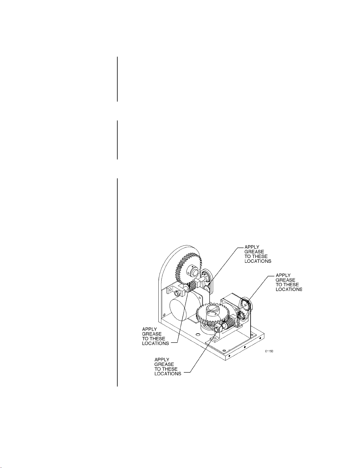
CHAIN DRIVE LUBRICATION
Sprockets, chains, and gears should be well greased. If necessary, lubricate the pan and tilt
gears, sprockets, and chains as follows with a high-quality grease capable of withstanding
temperatures from -50° to 170°F (-46° to 77°C). Do the following:
1. Liberally apply grease to the pan and tilt gears, chains, and sprockets (refer to Figure 1).
2. Operate the pan and tilt motors to spread the grease across the parts.
3. Apply additional grease if necessary.
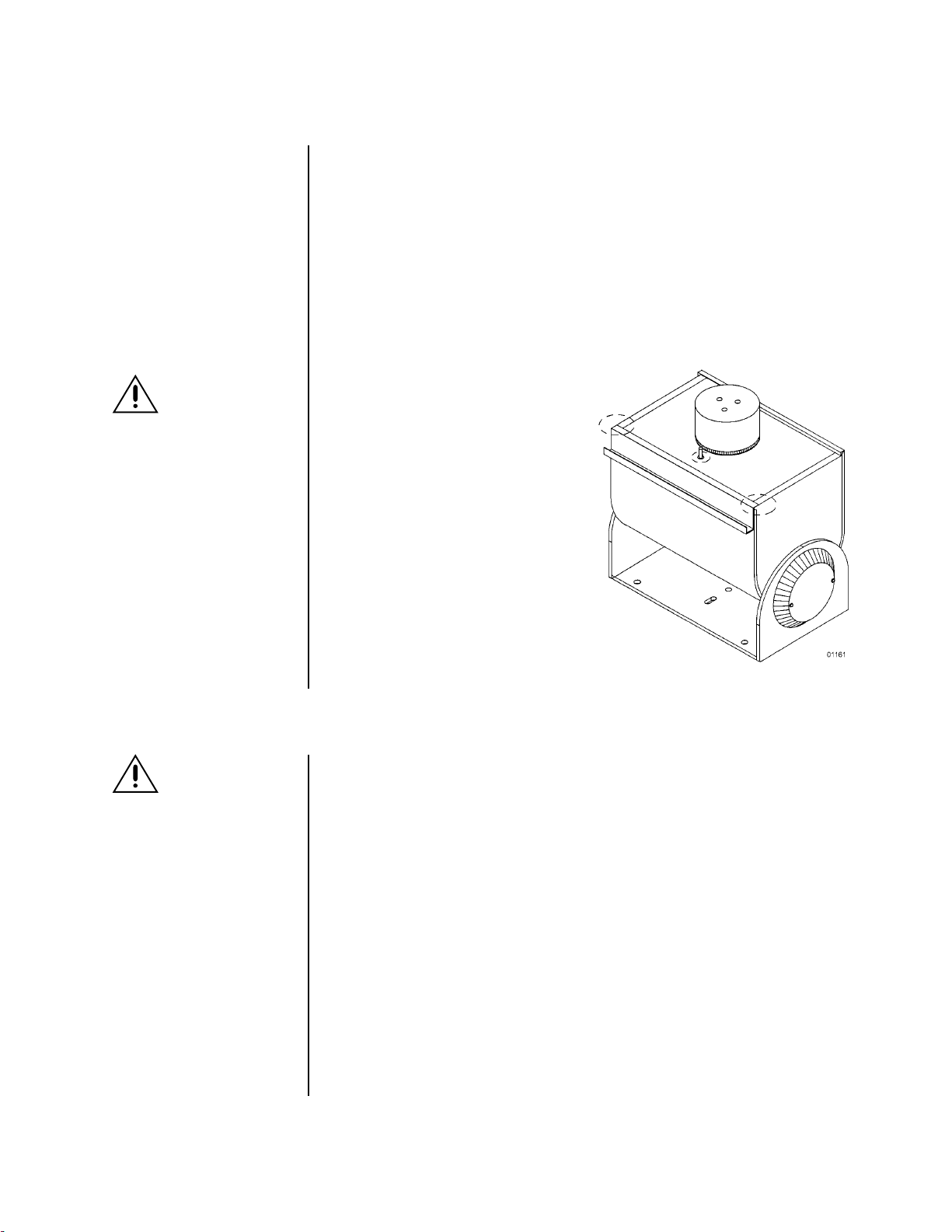
4. Reinstall the cover. If the pan/tilt is installed outdoors in an inverted position, apply
RTV silicone sealant as shown in Figure 2 (except PT1250EX/AMS and PT1260EX
Series).
Figure 1. Servicing the Pan/Tilt
Pelco Manual C373SM-A (8/01) 7
Page 8
RESETTING POTENTIOMETERS
IMPORTANT:
Be very
careful when resetting potentiometer switches. Be
sure that the pan/tilt has
been centered between
maximum pan and tilt travel,
regardless of the adjustable
limit stops. Failure to observe caution when resetting potentiometers could
result in damage to the
preset positioning ability of
the pan/tilt.
WARNING:
NEVER reposition
the pan fixed limit
stop. Doing so WILL DAMAGE the wiring harness
and, if the pan/tilt has preset
positioning, COULD cause
the pan potentiometer to
BREAK.
Models with Preset Positioning (PP)
Models with preset positioning (PP) use potentiometer switches that are factory set to the
full range of pan and tilt travel. Under normal operating conditions and at routine service
intervals they do not need adjusting.
Should your pan/tilt require any work on the drive mechanism other than routine maintenance, perform the following procedure to reset the potentiometers.
To begin, remove the cover to gain access to the pan and tilt motor assemblies.
1. Remove the potentiometer gears and position the pan/tilt to the middle of its maximum
pan and tilt travel, regardless of the position of the adjustable limit stops. That is, the
tilt table should be level and the fixed limit stop should be opposite the limit switch.
2. Turn a potentiometer all the way in
one direction until it stops, then
observing the number of turns, turn it
back the other way until it stops.
Rotate the potentiometer half the
number of turns the other way to
reach the center.
3. Replace the potentiometer gear.
4. Perform steps 2 and 3 for the other
potentiometer.
➛
➛
➛
WARNING
: The
knife-blade included in the brake
kit is very sharp. It should be
handled carefully and disposed of properly after use.
NOTE
: This section does
not apply to the PT1250DC
Series.
Figure 2. Sealant Locations
MOTOR BRAKE REPLACEMENT
To order replacement motor brakes, specify part number 1250BRAKE. The kit consists of
four springs, four Teflon pads, two screws, and a small knife-blade for removing the old
brake pads.
1. Remove the large rectangular heat sink from the back of the pan motor. Remove the
four springs. Do not disturb the silicone heat sink compound. It ensures the transfer of
heat to the heat sink and MUST be present when the heat sink is replaced.
2. Use the knife blade to remove the worn pads, as follows:
a. Insert the knife blade into the opening and press firmly into the brake pad.
b. Before trying to remove the brake pad, twist the knife-blade. This will loosen the
worn pad and make removal easier.
c. Gently twist the blade as you pull the worn pad out.
3. Insert the four new brake pads and four springs. Replace the heat sink using the new
screws.
Reinstall the cover. If your pan/tilt is installed outdoors in an inverted position, apply RTV
silicone sealant to the areas circled in Figure 2 (except PT1250EX/AMS and PT1260EX
Series).
8 Pelco Manual C373SM-A (8/01)
Page 9
EXPLODED ASSEMBLY DIAGRAMS
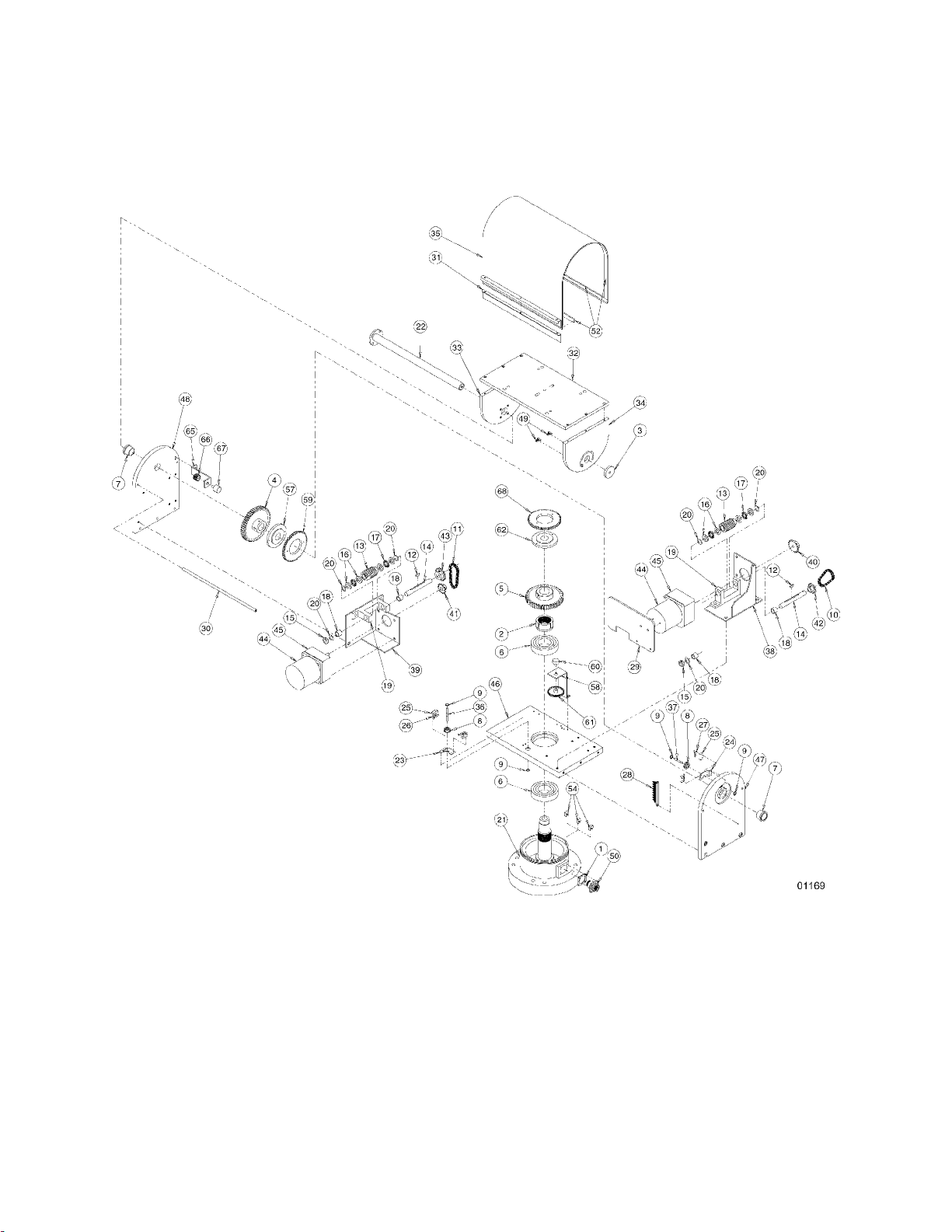
Figure 3. PT1250 Series Exploded Assembly Diagram (Mechanical Parts)
Pelco Manual C373SM-A (8/01) 9
Page 10

Table A. PT1250 Series Mechanical Parts List
Item Qty Description Part Number
11Gasket 105010010
21Pan spindle nut 10504017COMP
31Thrust cap (except WT, RAD models) 10504076COMP
41Tilt gear 10504084COMP
51Pan gear 10504089COMP
62Bearing 10506009
72Bearing 10506010
82Grommet 125010000
94Retainer clip 125010001
10 1 Pan chain assembly (except 220, FG, FGP models) 12501010COMP
11 1 Tilt chain assembly (except 220 , FG, FGP models) 12501011COMP
12 2 Key 105010015
13 2 Worm gear 105012010
14 2 Shaft (except 220 model) 10504078COMP
15 2 Thrust collar 10504085COMP
16 8 Bearing washer 10506005
17 4 Bearing cage 10506006
18 4 Bearing 10506007
19 2 Gear train bracket 12504079COMP
20 8 Arbor shim ZHSHIM.004
21 1 Spindle base assembly (except WT, RAD models) 12501041ACOMP
22 1 Tilt shaft assembly 12501043COMP
23 1 Pan limit bracket 12504100COMP
24 1 Tilt limit bracket 1554052COMP
25 4 Switch SWI1SM1
26 2 Pan switch actuator with insulation SWIJS221
27 2 Tilt switch actuator with insulation SWIJS138B
28 1 9-pin terminal strip TRS2009
29 1 Heat sink (except 220, RAD models) 12504010ACOMP
30 2 Spacer rod 12504110COMP
31 1 Pull-up bar (except WT, RAD models) 12504111COMP
32 1 Tilt table top (except WT , RAD models) 12504116COMP
33 1 Tilt table side (except WT, RAD models) 12504117COMP
34 1 Tilt table side (limit stops) (except WT, RAD models) 12504118COMP
35 1 Cover (except WT, RAD models) 12504119BWA
36 1 Pan limit pin 12504120ACOMP
37 1 Tilt limit pin 12504121ACOMP
38 1 Pan motor plate (except 220 model) 12504123COMP
39 1 Tilt motor plate (except 220 model) 12504123TCOMP
40 1 Pan motor sprocket (except 220, FG, FGP models) 12504124COMP
41 1 Tilt motor sprocket (except 220, FG models) 12504125COMP
42 1 Pan sprocket 12504126COMP
1 Thrust cap (WT and RAD only) 10504076WCOMP
1 Pan chain assembly (FG and FGP only) 12501020COMP
1 Pan chain assembly (220 only) 12501221COMP
1 Tllt chain assembly (FG and FGP only) 12501001COMP
1 Tilt chain assembly (220 only) 12501220COMP
2 Shaft (220 only) 20004110COMP
1 Spindle base assembly (WT and RAD only) 12501041AWCOMP
1 Pull-up bar (WT and RAD only) 12504111WCOMP
1 Tilt table top (WT and RAD only) 12504116WCOMP
1 Tilt table side (WT and RAD only) 12504117WCOMP
1 Tilt table side (limit stops) (WT and RAD only) 12504118WCOMP
1 Cover (WT and RAD only) 12504119WA
1 Pan motor plate (220 only) 12504220COMP
1 Tilt motor plate (220 only) 12504221COMP
1 Pan motor sprocket (FG and FGP only) 1504016 COMP
1 Pan motor sprocket (220 only) 12504226COMP
1 Tilt motor sprocket (220 only) 28012011
1 Tilt motor sprocket (FG only) 12504124COMP
Continued on next page
10 Pelco Manual C373SM-A (8/01)
Page 11

Table A. PT1250 Series Mechanical Parts List (Continued)
Item Qty Description Part Number
43 1 Tilt sprocket (except 220, FG models) 12504127COMP
44 2 Motor, 120 VAC (except 220 model) 12508110
45 2 Gear head (except 220 model) 12508111
46 1 Bottom plate 12504112ACOMP
47 1 Side plate, tilt side (except WT , RAD models) 12504115COMP
48 1 Side plate, pan side (except WT, RAD models) 12504114ACOMP
49 2 Tilt limit stop 1554055COMP
50 1 7-pin male connector (RAD model) MS3102E16S1P
51 Not used
52 7 Gasket, 1/8" x 1/2" x feet (except FG, FGP models) EH550010030
53 Not used
54 3 Pan limit stop 58010006
55 Not used
56 Not used
57 1 Collar, tilt AZL gear 12504020COMP
58 1 AZL potentiometer bracket 12504003COMP
59 1 Gear, AZL collar 12504104
60 1 Potentiometer, 5K ohm POT005.0K10534
61 1 Gear potentiometer TV12000
62 1 Collar, pan AZL gear 12504001COMP
63 Not used
64 Not used
65 1 AZL potentiometer bracket 12504003COMP
66 1 Gear TV12000
67 1 Potentiometer, 5K ohm POT005.0K10534
68 1 Gear, AZL collar 12504104
1 Tilt sprocket (220 only) 12504227COMP
1 Tilt sprocket (FG only) 12504126COMP
2 Motor, 230 VAC (220 only) 12508115
2 Gear head (220 only) 12508114
1 Side plate, tilt side (WT and RAD only) 12504115WCOMP
1 Side plate, pan side (WT and RAD only) 12504114AWCOMP
1 9-pin male connector (P, 220, FG, FGP models) CON206705-1
1 16-pin male connector (PP, WT, HB models) CON206036-1
2 Gasket, 1/8" x 1/2" x feet (FG and FGP only) EH550010030
The following items are for the PP and WT models only:
The following items are for the HB model only but are
not shown:
1Cover heater blanket, 120 VAC 105010000
2 Base heater blanket, 120 VA C EH110065A
1 Thermostat EH5510049A
Pelco Manual C373SM-A (8/01) 11
Page 12
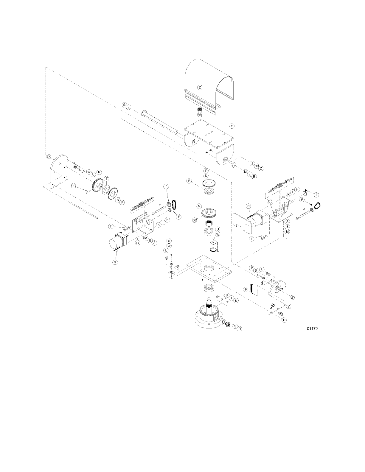
Figure 4. PT1250 Series Exploded Assembly Diagram (Hardware)
12 Pelco Manual C373SM-A (8/01)
Page 13

Table B. PT1250 Ser ies Hardware List
Item Qty Description Part Number
A4Screw, 1/4-20 x 1/2" ZH1/420X.500CH
B5Allen bolt, 1/4-20 x 5/8" ZH1/420X.625CS
C4Bolt, 1/4-20 x 3/4" ZH1/420X.750CH
D6Screw 1/4-20 x 1", flat-head, Phillips ZH1/420X1.00SFS
E9Split lock washer, 1/4" ZH1/4LWSSL
F4Set screw, 10-32 x 3/16" (except PP, WT models) ZH10-32X.187S
G8Screw, 10-32 x 2 1/4", pan head, Phillips ZH10-32X2.25SPS
H8Nut, 10-32 ZH10-32NUTSH
I8Split lock washer, #10 ZH10LWSSL
J2Flat washer, #8 ZH188X435X60C
K8Flat washer, #10 ZH204X436X60C
L8Screw, 2-56 x 7/16", pan head, Phillips ZH2-56X.437SPP
M5Flat washer, 3/16" ZH260X562X65C
N2Set screw, 3/8-24 x 3/8" ZH3/8-24X.375S
P4
R4Screw, 4-40 x 3/8", pan head, Phillips ZH4-40X.375SPP
S6Internal tooth lock washer, #4 (except PP, WT) ZH4LWSIS
T3Set screw, 6-32 x 3/16" ZH6-32X.187S
U4
V4Screw, 6-32 x 3/4" flat head, Phillips ZH6-32X.750SFS
W2Split lock washer, #6 (except PP, WT) ZH6LWSIS
X Not used
Y6Allen screw, 8-32 x 1/2" ZH8-32X.500CS
Z5Screw, 8-32 x 5/8", pan head, Phillips ZH8-32X.625SPP
AA 3 Nut, 8-32 ZH8-32NUTSH
BB 5 Internal star washer, #8 ZH8LWSIS
CC 1 Tapered pin, #5 x 2 1/2" 105010017
DD 1 Dowel pin, 3/16" x 5/8" ZHPIN3/16X5/8
6 Set screw, 10-32 x 3/16" (PP and WT only) ZH10-32X.187S
8 Screw, 4-40 x 1/4", pan head, Phillips (PP, WT only) ZH4-40X.250SPP
Screw, 4-40 x 1/4", pan head, Phillips (except PP, WT
10 Internal tooth lock washer, #4 (PP and WT only) ZH4LWSIS
Screw, 6-32 x 3/8", pan head, Phillips (except PP, WT
6 Screw, 6-32 x 3/8", pan head, Phillips (PP, WT only) ZH6-32X.375SPP
6 Split lock washer, #6 (PP and WT only) ZH6LWSIS
) ZH4-40X.250SPP
) ZH6-32X.375SPP
Pelco Manual C373SM-A (8/01) 13
Page 14
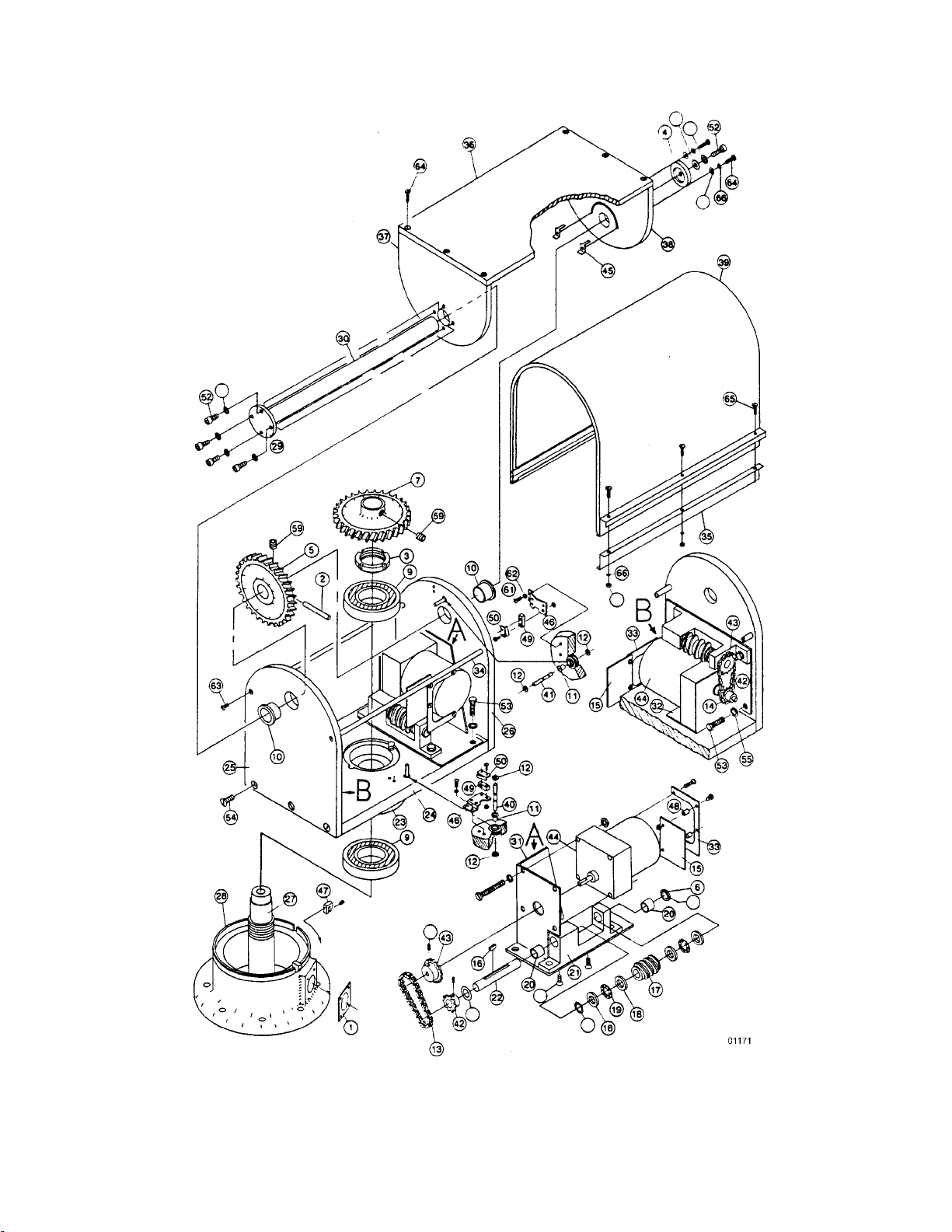
Figure 5. PT1250DC Series Exploded Assembly Diagram
14 Pelco Manual C373SM-A (8/01)
Page 15

Table C. PT1250DC Series Parts List
Item Qty Description Part Number
11Gasket connector 105010010
21Pin tapper #5 x 2" 105010017
31Nut, pan spindle 10504017COMP
41Thrust cap 10504076COMP
51Gear tilt 10504084COMP
62Thrust collar 10504085COMP
71Gear, pan 10504089COMP
8–(Not used)
92Bearing 10506009
10 2 Bearing 10506010
11 2 Mount limit pin 125010000
12 4 Clip retainer 125010001
13 1 Chain assembly, pan motor 12501000COMP
14 1 Chain assembly, tilt motor 12501001COMP
15 2 PC board assembly filter 12501003COMP
16 2 Key, Woodruff #3 105010015
17 2 Gear, worm pan/tilt 105012010
18 8 Bearing, A016 washer only 10506005
19 4 Bearing, A016C cage only 10506006
20 6 Bearing 10506007
21 2 Bracket, gear train 12504079COMP
22 2 Shaft, gear train 20004110COMP
23 1 Bearing, boss 10504069COMP
24 1 Bottom plate 12504113ACOMP
25 1 Pan side plate 12504114ACOMP
26 1 Tilt side plate 12504115ACOMP
27 1 Spindle 10504074COMP
28 1 Base 12504112ACOMP
29 1 Flange, tilt 10504077COMP
30 1 Shaft, tilt (less flange) 12504122COMP
31 1 Plate, pan motor 12504006COMP
32 1 Plate, tilt motor 12504007COMP
33 2 Bracket, circuit board 12504009COMP
34 2 Spacer, rod 12504110COMP
35 1 Pull-up bar 12504111COMP
36 1 Tilt table top 12504116COMP
37 1 Table, side tilt 4H 12504117COMP
38 1 Table, side tilt 1H 12504118COMP
39 1 Cover 12504119BWA
40 1 Pin limit, pan 12504120ACOMP
41 1 Pin limit, tilt 12504121ACOMP
42 2 Sprocket, pan gear train 12504126ACOMP
43 2 Sprocket, tilt gear train 12504127ACOMP
44 2 Motor MR02-0002-3104
45 2 Tilt limit stop 1554050COMP
46 2 Bracket, tilt limit 1554052COMP
47 3 Limit stop pan, univ pan/tilt 58010006
48 4 Spacer, 1/4 O.D. x .375 ##6, clear SPA2101
49 4 Switch SWI1SM1
50 2 Pan switch actuator w/insulator SWIJS138B
51 4 Screw, 1/4-20 x 1/2" Hex CAD ZH1/4-20X.500CH
52 5 Bolt, 1/4-20 x 5/8" SOC SS ZH1/420X.625CS
53 4 Bolt, 1/4-20 x 3/4" Hex CAD ZH1/420X.750CH
54 6 Screw, 1/4-20 x 1" Flat slot SS ZH1/420X1.00SFS
2 Tilt switch actuator w/insulator SWIJS221
Pelco Manual C373SM-A (8/01) 15
Page 16

35
31
22
33
48
4
7
20
18
20
15
30
45
44
20
17
13
16
12
18
19
25
26
23
11
43
14
41
39
49
5
2
6
46
9
36
8
9
6
52
32
34
3
20
17
13
16
20
19
45
44
29
9
28
54
18
20
15
37
8
27
25
24
9
47
40
12
10
42
14
18
38
7
21
1
50
01172
Figure 6. PT1253R Exploded Assembly (Mechanical Parts)
16 Pelco Manual C373SM-A (8/01)
Page 17

Table D. PT1253R Mechanical Parts List
Item Qty Description Part Number
11Gasket, connector 105010010
21Nut, pan spindle black no. 8 10504017COMP
31Thrust cap 10504076COMP
41Gear, tilt 10504084COMP
51Gear, pan 10504089COMP
62Bearing 6208-ZZ 10506009
72Bearing FB1416-6 10506010
82Mount grommet LOR00 125010000
94Clip retainer 125010001
10 1 Chain, assy pan 12501010COMP
11 1 Chain, assy tilt 12501011COMP
12 2 Key, Woodruff #3 alloy 105010015
13 2 Gear, worm pan 105012010
14 2 Pan shaft 10504078COMP
15 2 Thrust collar 10504085COMP
16 8 Bearing AO16, washer only 10506005
17 4 Bearing AO16C, cage only 10506006
18 4 Bearing B810-4 10506007
19 2 Bracket, gear train 12504079COMP
20 6 Shim arbor ZHSHIM.004
21 1 Base, spindle assy 12501041ACOMP
22 1 Tilt, shaft assy 12501043COMP
23 1 Pan limit bracket 12504100COMP
24 1 Tilt limit bracket 1554052COMP
25 4 Switch SWI1SM1
26 2 Switch actuator w/ insulation SWIJS138B
27 2 Switch actuator, long w/insulation SWIJS221
28 1 Terminal strip, 9 position TRS2009
29 1 Heat sink 12504010ACOMP
30 2 Spacer rod 12504110COMP
31 1 Pull up bar 12504111COMP
32 1 Tilt table, top 12504116COMP
33 1 Table, side tilt 4H 12504117COMP
34 1 Table, side tilt 1H 12504118COMP
35 1 Cover 12504119BWA
36 1 Pin, limit pan 12504120ACOMP
37 1 Pin, limit tilt 12504121ACOMP
38 1 Plate, motor pan 12504123COMP
39 1 Plate, motor tilt 12504123TCOMP
40 1 Sprocket, 25B18-5/16" W/SS 12504124COMP
41 1 Sprocket, motor tilt 12504125COMP
42 1 Sprocket, 25B13 1/2" bore w/ set screw 12504126COMP
43 1 Sprocket, 25B18 1/2" bore w/ set screw 12504127COMP
44 2 Motor, 120V 12508110
45 2 Gear head 12508111
46 1 Bottom plate assy 12504112ACOMP
47 1 Tilt, side plate 12504115COMP
48 1 Pan, side plate 12504114ACOMP
49 2 Tilt, limit stop 1554050COMP
50 1 Conn CPC 16 pos pin recp CON206036-1
51 1 PCB Assy, Frame Scan (not shown) 12501007ACOMP
52 7 ft. Gasket, poron 1/8 x 1/2, black EH550010030
53 Not Used
54 3 Limit stop, pan 58010006
Pelco Manual C373SM-A (8/01) 17
Page 18

Z
B
E
CC
N
F
T
K
M
E
A
C
G
F
H
I
U
W
L
BB
AA
Y
J
BB
Z
M
E
B
N
DD
G
T
C
H
I
K
A
E
M
F
F
P
L
S
P
U
T
U
S
R
V
D
01173
Figure 7. PT1253R Exploded Assembly (Hardware)
18 Pelco Manual C373SM-A (8/01)
Page 19

Table E. PT1253R Hardware List
Item Qty Description Part Number
A4Screw, 1/4-20 x .500 soc ZH1/420X.500CS
B5Bolt, 1/4-20 x 5/8" sock SS ZH1/420X.625CS
C4Bolt, 1/4-20 x 3/4" hex SS ZH1/420X.750CH
D6Screw, 1/4-20 x 1" flat phil SS ZH1/420X1.00SFS
E9Washer, split lock 1/4" SS ZH1/4LWSSL
F4Set screw, 10-32 x 3/16" soc knur blk ZH10-32X.187S
G8Screw, 10-32 x 2 1/4" phil pan SS ZH10-32X2.25SPS
H8Nut, hex 10-32 SS ZH10-32NUTSH
I8Washer, split lock #10 SS ZH10LWSSL
J2Washer, flat #8 SS ZH188X435X60C
K8Washer, flat #10 ZH204X436X60C
L8Screw, 2-56 x 7/16" pan phil SS ZH2-56X.437SPP
M5Washer, flat 3/16" SS ZH260X562X65C
N2Set screw, 3/8-24 x 3/8" soc knur blk ZH3/8-24X.375S
P4Screw, 4-40 x 1/4" pan phil SS ZH4-40X.250SPP
R4Screw, 4-40 x 3/8" pan phil SS ZH4-40X.375SPP
S6Washer, lock #4 internal tooth SS ZH4LWSIS
T3Set screw, 6-32 x 3/16" soc knur blk ZH6-32X.187S
U6Screw, 6-32 x 3/8" pan phil SS ZH6-32X.375SPP
V4Screw, 6-32 x 3/4" flat phil SS ZH6-32X.750SFS
W4Washer, split lock #6 ZH6LWSIS
X3Screw, 8-32 x 3/8" pan phil SS ZH8-32X.375SPP
Y6Screw, 8-32 x 1/2" soc SS ZH8-32X.500CS
Z5Screw, 8-32 x 5/8" pan phil SS ZH8-32X.625SPP
AA 3 Nut, hex 8-32 SS ZH8-32NUTSH
BB 5 Washer, internal star #8 SS ZH8LWSIS
CC 1 Taper pin, #5 x 2 1/2" ZHPIN#5X21/2
DD 1 Pin, dowel 3/16" x 5/8" ZHPIN3/16X5/8
Pelco Manual C373SM-A (8/01) 19
Page 20

20 Pelco Manual C373SM-A (8/01)
Figure 8. PT1250EX/AMS Exploded Assembly Diagram
Page 21

Table F. PT1250EX/AMS Parts List
Item Qty Description Part Number
1 Not used
21Pan spindle nut 10504017COMP
31Thrust cap 10504076WCOMP
41Tilt gear 10504084COMP
51Pan gear 10504089COMP
61Upper pan shaft bearing 10506009
71Lower pan shaft bearing 10506012
81Pan chain assembly 12501010COMP
91Tilt chain assembly 12501011COMP
10 2 Key 105010015
11 2 Worm gear 105012010
12 2 Worm gear shaft 10504078COMP
13 2 Thrust collar 10504085COMP
14 8 Bearing washer 10506005
15 4 Bearing cage 10506006
16 4 Bearing 10506007
17 2 Gear train bracket 12504079COMP
18 8 Arbor shim ZHSHIM.004
19 1 Tilt shaft 12501043SSCOMP
20 1 Heat sink 12504010ACOMP
21 2 Tilt collar 12504020COMP
22 1 Mounting for pan limit ring and preset position gear 12504101COMP
23 2 Preset position gear 12504104
24 1 Tilt table top 12504116WCOMP
25 1 Pan motor plate 12504123COMP
26 1 Sprocket 12504124COMP
27 1 Sprocket 12504125COMP
28 1 Sprocket 12504126COMP
29 1 Sprocket 12504127COMP
30 2 120 VAC motor 12508110
31 2 Gear head 12508111
32 1 Spindle base 1250EX1043COMP
33 1 Body 1250EX1141WCOMP
34 1 Potentiometer bracket 12550EX4003WA
35 2 Limit stop ring 1250EX4005COMP
36 1 Tilt switch bracket 1250EX4006COMP
37 1 Pan switch bracket 1250EX4007COMP
38 1 Heat sink bracket 1250EX4008COMP
39 1 Tilt table side plate, tilt side 1250EX4213WCOMP
40 1 Tilt table side plate, pan side 1250EX4116WCOMP
41 1 Tilt motor plate 1250EX4123TCOMP
42 2 Bushing 1250EX6000
43 4 Retainer clip 125010001
44 Not used
45 6 Limit stop 58010006
46-48 Not used
49 2 Grommet GRO2172N
50 2 Potentiometer, 5K ohm POT005.0K10534
51 2 Actuator pin PT18044020COMP
52 4 Switch SWI1SM1
53 4 Actuator with insulator SWIJS138B
54 Not used
55 1 Terminal strip TRS2009
56 2 Gear TV12000
57 2 Cover 1250EX4218WCOMP
2 Cover gasket (not shown) 1250EX10002
Continued on next page
Pelco Manual C373SM-A (8/01) 21
Page 22

Table F. PT1250EX/AMS Parts List (Continued)
Item Qty Description Part Number
A Not used
B6Allen screw, 8-32 x 1/2" ZH8-32X.500CS
C-E Not used
F6Internal star lock washer, #6 ZH6LWSIS
G Not used
H8Flat washer, #10 ZH204X436X60C
I-J Not used
K12Split lock washer, 1/4" ZH1/4LWSSL
L-M Not used
N3Allen screw, 6-32 x 3/8" ZH6-32X.375CS
O Not used
P9Flat washer, 3/16" ZH260X562X65C
Q1Internal star lock washer, 1/4" ZH1/4LWSIS
R-S Not used
T3Split lock washer, #6 ZH6LWSSL
U8Split lock washer, #10 ZH10LWSSL
V-W Not used
X8Screw, 2-56 x 7/16", pan head ZH2-56X.437SPP
Y8Screw, 4-40 x 3/8", pan head ZH4-40X.375SPP
Z-AA Not used
BB 4 Internal star lock washer, #4 ZH4LWSIS
CC 5 Screw, 6-32 x 3/8", pan head ZH6-32X.375SPP
DD 3 Set screw, 6-32 x 3/16" ZH6-32X.187S
EE 2 Screw, 4-40 x 1/4", pan head ZH4-40X.250SPP
FF Not used
GG 5 Allen bolt, 1/4-20 x 5/8" ZH1/420X.625CS
HH 2 Set screw, 3/8-24 x 3/8" ZH3/8-24X.375S
II 9 Set screw, 10-32 x 3/16" ZH10-32X.187S
JJ 6 Screw, 6-32 x 1/4", pan head ZH6-32X.250SPP
KK 4 Bolt, 1/4-20 x 1/2" ZH1/4-20X.500CH
LL 24 Allen bolt, 1/4-20 x 3/4" ZH1/4-20X.750CS
MM 4 Bolt, 1/4-20 x 3/4" ZH1/420X.750CH
NN 2 Nut, 4-40 ZH4-40NUTSH
OO Not used
PP 9 Nut, 10-32 ZH10-32NUTSH
QQ 2 Screw, 10-32 x 1/2", pan head ZH10-32X.500SPP
RR 8 Screw, 10-32 x 2-1/4", pan head ZH10-32X2.25SPS
SS 1 Tapered pin, #5 x 2" 105010017
TT 2 Dowel pin, 3/16” x 5/8" ZHPIN3/16X5/8
UU 8 Nylon washer ZH131X361X62N
22 Pelco Manual C373SM-A (8/01)
Page 23

Figure 9. PT1260EX and PT1260EX/PP Exploded Assembly Diagram (Mechanical Parts)
Pelco Manual C373SM-A (8/01) 23
Page 24

Table G. PT1260EX Series Mechanical Parts List
Item Qty Description Part Number
1—Not used —
21Nut, pan spindle 10504017COMP
31Thrust cap 10504076COMP
41Gear, tilt 10504084COMP
51Gear, pan 10504089COMP
62Bearing, pan shaft 10506012
7—Not used —
81Chain assembly, pan 12501010COMP
91Chain assembly, tilt 12501011COMP
10 2 Key, Woodruff #3 105010015
11 2 Gear, worm 105012010
12 2 Shaft, worm gear 10504078COMP
13 2 Collar, thrust 10504085COMP
14 8 Bearing, washer only 10506005
15 4 Bearing, cage only 10506006
16 4 Bearing 10506007
17 2 Bracket, gear train 12504079COMP
18 8 Shim, arbor ZHSHIM.004
19 1 Shaft, tilt 12501043SSCOMP
20 1 Heat sink 12504010ACOMP
21 1 Collar, tilt (non-preset models) 12504020COMP
22 1 Mount, pan limit ring 12504101COMP
23 2 Gear, AZL collar (preset models only) 12504104
24 1 Tilt table 12504116COMP
25 1 Plate, motor pan 12504123COMP
26 1 Sprocket, with set screw 12504124COMP
27 1 Sprocket, with set screw 12504125COMP
28 1 Sprocket, with set screw 12504126COMP
29 1 Sprocket, with set screw 12504127COMP
30 2 Motor only: 120 VAC 12508110
31 2 Gear head only: 120 VAC 12508111
32 1 Spindle base 1260EX1042COMP
33 1 Body 1250EX1141COMP
34 1 Bracket, AZL pots (preset models only) 1250EX4003WA
35 2 Ring, limit stop 1250EX4005COMP
36 1 Bracket, tilt switch 1250EX4006COMP
37 1 Bracket, pan switch 1250EX4007COMP
38 1 Bracket, heat sink 1250EX4008COMP
39 1 Side plate, tilt table, tilt side 1250EX4213COMP
40 1 Side plate, tilt table, pan side 1250EX4116COMP
41 1 Plate, motor tilt 1250EX4123TCOMP
42 2 Bushing 1250EX6000
43 4 Retainer, clip 125010001
44 — Not Used
45 6 Limit stop universal 58010006
46 1 Plate, UL label (not Shown) 1260EX4000COMP
47 — Not used —
48 — Not used —
49 2 Grommet (special) GRO2172N
50 2 Potentiometer, 5K ohm (preset models only) POT005.0K10534
51 2 Pin, actuator PT18044020COMP
52 4 Switch SWI1SM1
53 4 Actuator with insulator SWIJS138B
54 — Not used —
55 1 Terminal Strip TRS2009
56 2 Gear, AZL (preset models only) TV12000
57 2 Cover, front/rear 1250EX4218COMP
58 1 Pipe nipple 1/2" x 4" galv. 1250EX10000
59 1 Gland, explosion proof EHX82410084
2 Collar, tilt (preset models) 12504020COMP
Motor only: 230 VAC 12508115
Gear head only: 230 VAC 12508114
UL Label (not shown) ULBL02
2 Gasket, cover (not shown) 1250EX10002
24 Pelco Manual C373SM-A (8/01)
Page 25

Table H. PT1260EX Ser ies Hardware List
Item Qty Description Part Number
A—Not used —
B6Screw, 8-32 x 1/2" Hex socket head ZH8-32X.500CS
C—Not used —
D—Not used —
E—Not used —
F6Lockwasher #6 internal star ZH6LWSIS
G—Not used —
H8Flat, washer #10 ZH204X436X60C
I—Not used —
J—Not used —
K12Washer, split lock 1/4" ZH1/4LWSSL
L—Not used —
M—Not used —
N3Screw, 6-32 x 3/8", socket head (preset models only) ZH6-32X.375CS
O—Not used —
P9Washer, flat 3/16" special ZH260X562X65C
Q1Lockwasher, 1/4" internal star ZH1/4LWSIS
R—Not used —
S—Not used —
T3Split lock washer, #6 (preset models only) ZH6LWSSL
U8Washer, #10 split lock ZH10LWSSL
V—Not used —
W—Not used —
X8Screw 2-56 x 7/16" pan head ZH2-56X.437SPP
Y4Screw 4-40 x 3/8" pan head (non-preset models) ZH4-40X.375SPP
Z—Not used —
AA — Not used —
BB 4 Lockwasher #4 internal star ZH4LWSIS
CC 5 Screw 6-32 x 3/8" pan head ZH6-32X.375SPP
DD 3 Set screw 6-32 x 3/16" socket head knur black ZH6-32X.187S
EE 2 Screw 4-40 x 1/4" pan head ZH4-40X.250SPP
FF — Not used —
GG 5 Bolt 1/4-20 x 5/8" hex socket head ZH1/420X.625CS
HH 2 Set screw 3/8-24 x 3/8" hex socket knur black ZH3/8-24X.375S
II 7 Set screw 10-32 x 3/16" hex socket knur black (non-preset models) ZH10-32X.187S
JJ 6 Screw 6-32 x 1/4" pan head ZH6-32X.250SPP
KK 4 Bolt 1/4-20 x 1/2" hex head ZH1/4-20X.500CH
LL 24 Bolt 1/4-20 x 3/4" hex socket head ZH1/420X.750CS
MM 4 Bolt 1/4-20 x 3/4" hex head ZH1/420X.750CH
NN 2 Nut, Hex 4-40 ZH4-40NUTSH
OO — Not used —
PP 9 Nut, Hex 10-32 ZH10-32NUTSH
QQ 2 Screw 10-32 x 1/2" pan head ZH10-32X.500SPP
RR 8 Screw 10-32 x 2-1/4" pan head ZH10-32X2.25SPS
SS 1 Pin, taper #5 x 2" 105010017
TT 2 Pin, dowel 3/16" x 5/8" ZHPIN3/16X5/8
UU 8 Washer, nylon ZH131X361X62N
8 Screw 4-40 x 3/8" pan head (preset models) ZH4-40X.375SPP
9 Set screw 10-32 x 3/16" hex socket knur black (preset models) ZH10-32X.187S
Pelco Manual C373SM-A (8/01) 25
Page 26

35
31
7
*PT1280P ONLY
**PT1280SL ONLY
22
33
48
4
20
17
13
16
20
18
18
20
30
15
45
44
19
25
*
26
*
23
*
11
43
14
12
41
39
49
56
**
55
**
5
2
6
53
46
9
*
36
*
8
*
9
*
6
21
52
32
34
3
20
17
13
16
20
19
45
44
29
9
54
28
*
18
20
15
37
8
27
25
24
9
47
40
12
10
42
14
18
38
7
1
50
51
01151
Figure 10. PT1280P and PT1280SL Exploded Assembly (Mechanical Parts)
26 Pelco Manual C373SM-A (8/01)
Page 27

Table I. PT1280P and PT1280SL Mechanical Parts List
Item Qty Description Part Number
11Gasket, connector 105010010
21Nut, pan spindle black no.8 10504017COMP
31Thrust cap 10504076COMP
41Gear, tilt 10504084COMP
51Gear, pan 10504089COMP
62Bearing 6208-ZZ 10506009
72Bearing FB1416-6 10506010
82 (1) Mount grommet LOR00 125010000 (SL)
94 (2) Clip retainer 125010001 (SL)
10 1 Chain, assy pan 12501010COMP
11 1 Chain, assy tilt 12501011COMP
12 2 Key, Woodruff #3 alloy 105010015
13 2 Gear, worm pan 105012010
14 2 Pan shaft 10504078COMP
15 2 Thrust collar 10504085COMP
16 8 Bearing AO16, washer only 10506005
17 4 Bearing AO16C, cage only 10506006
18 4 Bearing B810-4 10506007
19 2 Bracket, gear train 12504079COMP
20 6 Shim arbor ZHSHIM.004
21 1 Base, spindle assy 12501041ACOMP
22 1 Tilt, shaft assy 12501043COMP
23 1 Pan limit bracket 12504100COMP
24 1 Tilt limit bracket 1554052COMP
25 4 (2) Switch SWI1SM1 (SL)
26 2 Switch actuator w/insulation SWIJS138B
27 2 Switch actuator, long w/insulation SWIJS221
28 1 Terminal strip, 9 position TRS2009
29 1 Heat sink 12504010ACOMP
30 2 Spacer rod 12504110COMP
31 1 Pull up bar 12504111COMP
32 1 Tilt table, top 12504116COMP
33 1 Table, side tilt 4H 12504117COMP
34 1 Table, side tilt 1H 12504118COMP
35 1 Cover 12504119BWA
36 1 Pin, limit pan 12504120ACOMP
37 1 Pin, limit tilt 12504121ACOMP
38 1 Plate, motor pan 12504123COMP
39 1 Plate, motor tilt 12504123TCOMP
40 1 Sprocket 25B18-5/16" W/SS 12504124COMP
41 1 Sprocket, motor tilt 12504125COMP
42 1 Sprocket, 25B13 1/2" bore w/set screw 12504126COMP
43 1 Sprocket, 25B18 1/2" bore w/set screw 12504127COMP
44 2 Motor 115V 12508110
45 2 Gear head 12508111
46 1 Bottom plate 12504112ACOMP
47 1 Tilt, side plate 12504115COMP
48 1 Pan, side plate 12804114COMP
49 2 Tilt, limit stop 1554050COMP
50 1 Conn CPC 16 pos pin recp CON206036-1
51 2 UL, gland, SL-9 EH400010003
52 7 FT Gasket poron 1/8 x 1/2, black EH550010030
53 1Term strip, 11 pin TRS2011
54 3 Limit, stop pan 58010006 (P ONLY)
55 1 Bracket, slip ring 12804002COMP (SL ONLY)
56 1 Ring, slip #AC4023-18A 28010000 (SL ONLY)
Pelco Manual C373SM-A (8/01) 27
Page 28

CC
Z
B
E
N
F
T
K
M
E
C
A
G
F
H
I
U
*
W
*
L
*
DD
BB
AA
Y
J
BB
X
**
U
**
W
**
N
U
G
Z
M
E
B
C
T
H
I
K
A
E
M
F
F
P
L
S
*PT1280 Only
**PT1280SL Only
*
U
P
*
T
*
U
S
R
V
D
Figure 11. PT1280P and PT1280SL Exploded Assembly (Hardware)
28 Pelco Manual C373SM-A (8/01)
01152
Page 29

Table J. PT1280P and PT1280SL Hardware List
Item Qty Description Part Number
A4Screw, 1/4-20 x .500 soc ZH1/420X.500CS
B5Bolt, 1/4-20 x 5/8" sock SS ZH1/420X.625CS
C4Bolt 1/4-20 x 3/4" hex SS ZH1/420X.750CH
D6Screw 1/4-20 x 1" flat phil SS ZH1/420X1.00SFS
E9Washer, split lock 1/4" SS ZH1/4LWSSL
F4Set screw 10-32 x 3/16" soc knur blk ZH10-32X.187S
G8Screw 10-32 x 2 1/4" phil pan SS ZH10-32X2.25SPS
H8Nut, hex 10-32 SS ZH10-32NUTSH
I8Washer, split lock #10 SS ZH10LWSSL
J2Washer, flat #8 SS ZH188X435X60C
K8Washer, flat #10 ZH204X436X60C
L8 (4) Screw 2-56 x 7/16" pan phil SS ZH2-56X.437SPP (SL ONLY)
M5Washer, flat 3/16" SS ZH260X562X65C
N2Set screw 3/8-24 x 3/8" soc knur blk ZH3/8-24X.375S
P4Screw 4-40 x 1/4" pan phil SS ZH4-40X.250SPP
R4Screw 4-40 x 3/8" pan phil SS ZH4-40X.375SPP
S6Washer lock #4 internal tooth SS ZH4LWSIS
T3Set screw 6-32 x 3/16" soc knur blk ZH6-32X.187S
U6 (4) Screw 6-32 x 3/8" pan phil SS ZH6-32X.375SPP (SL ONLY)
V4Screw 6-32 x 3/4" flat phil SS ZH6-32X.750SFS
W2 (2) Washer, split lock #6 ZH6LWSIS (SL ONLY)
X3Screw 8-32 x 3/8" pan phil SS ZH8-32X.375SPP
Y6Screw 8-32 x 1/2" soc SS ZH8-32X.500CS
Z5Screw 8-32 x 5/8" pan phil SS ZH8-32X.625SPP
AA 3 Nut, hex 8-32 SS ZH8-32NUTSH
BB 5 Washer, internal star #8 SS ZH8LWSIS
CC 1 Taper pin #5 x 2 1/2" ZHPIN#5X21/2
DD 1 Pin, dowel 3/16" x 5/8" ZHPIN3/16X5/8
Pelco Manual C373SM-A (8/01) 29
Page 30

35
31
22
33
48
65
66
67
7
30
4
57
59
20
18
20
15
45
44
* PT1280P/PP Only
** PT1280SL/PP Only
20
17
13
16
18
19
25
*
26
*
23
*
11
43
14
12
41
39
49
68
*
62
*
64
**
63
**
5
2
6
53
46
9
*
36
*
8
*
9
*
6
52
32
34
3
20
17
13
16
20
19
45
44
60
29
58
61
54
*
9
28
18
20
15
37
8
27
25
38
24
9
47
**
56
**
55
40
12
10
42
14
18
7
21
1
50
51
01153
Figure 12. PT1280P/PP and PT1280SL/PP Exploded Assembly Diagram (Mechanical Parts)
30 Pelco Manual C373SM-A (8/01)
Page 31

Table K. PT1280P/PP and PT1280SL/PP Mechanical Parts List
Item Qty Description Part Number
11Gasket, connector 105010010
21Nut, pan spindle, black no.8 10504017COMP
31Thrust cap 10504076COMP
41Gear, tilt 10504084COMP
51Gear, pan 10504089COMP
62Bearing 6208-ZZ 10506009
72Bearing FB1416-6 10506010
82 (1) Mount grommet Loroo 125010000 (SL/PP)
94 (2) Clip retainer 125010001 (SL/PP)
10 1 Chain assy, pan 12501010COMP
11 1 Chain assy, tilt 12501011COMP
12 2 Key, Woodruff #3 alloy 105010015
13 2 Gear, worm pan 105012010
14 2 pan shaft 10504078COMP
15 2 Thrust collar 10504085COMP
16 8 Bearing, AO16, washer only 10506005
17 4 Bearing, A016C, cage only 10506006
18 4 Bearing B810-4 10506007
19 2 Bracket, gear train 12504079COMP
20 6 Shim arbor ZHSHIM.004
21 1 Base spindle assy 12501041ACOMP
22 1 Tilt shaft assy 12501043COMP
23 1 Pan limit bracket 12504100COMP
24 1 Tilt limit bracket 1554052COMP
25 4 (2) Switch SWI1SM1 (SL/PP)
26 2 (0) Switch actuator, long w/insulation SWIJS221 (SL/PP)
27 2 Switch actuator w/insulation SWIJS138B
28 1 Terminal strip, 9 pin TRS2009
29 1 Heat sink 12504010ACOMP
30 2 Spacer rod 12504110COMP
31 1 Pull up bar 12504111COMP
32 1 Tilt table top 12504116COMP
33 1 Table, side tilt 4H 12504117COMP
34 1 Table, side tilt 1H 12504118COMP
35 1 Cover 12504119BWA
36 1 (0) Pin, limit pan 12504120ACOMP (SL/PP)
37 1 Pin, limit tilt 12504121ACOMP
38 1 Plate, motor pan 12504123COMP
39 1 Plate, motor tilt 12504123TCOMP
40 1 Sprocket 25B18-5/16" W/SS 12504124COMP
41 1 Sprocket, motor tilt 12504125COMP
42 1 Sprocket, 25B13, 1/2" bore w/set screw 12504126COMP
43 1 Sprocket, 25B18, 1/2" bore w/set screw 12504127COMP
44 2 Motor, 115V 12508110
45 2 Gear head 12508111
46 1 Bottom plate 12504112ACOMP
47 1 Tilt side plate 12504115COMP
48 1 Pan side plate 12804114COMP
49 2 Bottom plate 1554055COMP
50 1 Conn 28 pos pin recp CON205840-3 (SL/PP, P/PP)
51 2 UL, gland, SL-9 EH400010003
52 7 FT Gasket, Poron 1/8 x 1/2, blk EH550010030
53 1Term strip, 11 pin TRS2011
54 3 Limit stop, pan 58010006 (P/PP only)
55 1 Bracket, slip ring 12804003COMP (SL/PP only)
56 1 Slip ring, 24 circuit 250010000
57 1 Collar, tilt AZL gear 12504020COMP
58 1 Bracket, AZL pot 12504003COMP (P/PP only)
59 1 Gear, AZL collar, polycarb 12504104
Bracket, pot (pan) 12804004COMP (SL/PP only)
Pelco Manual C373SM-A (8/01) 31
Page 32

Table K. PT1280P/PP and PT1280SL/PP Mechanical Parts List (Continued)
Item Qty Description Part Number
60 1 Pot model 534 5K OHM POT005.0K10534 (P/PP only)
Pot, dual arm pre res POTDARM01.0K (SL/PP only)
61 1 Gear potentiometer TV12000 (P/PP only)
Gear 1.875 plastic PT250010002 (SL/PP only)
62 1 Collar, pan AZL gear 12504001COMP
63 1 Hub, PP pan gear 12804005COMP
64 1 Gear, pan spindle feedback SL PT25004122COMP
65 1 Gear, polycarb TV12000
66 1 Bracket, AZL potentiometer 12504003COMP
67 1 Pot, model 534 5K OHM POT005.0K10534
68 1 Gear, AZL collar, polycarb 12504104
Z
B
E
BB
AA
Y
CC
J
BB
P
W
N
U
F
F
S
P
F
H
I
T
C
G
* PT1280P/PP Only
** PT1280SL/PP Only
K
M
E
U
A
*
W
*
L
*
*
S
*
F
*
N
F
**
DD
U
W
U
*
*
U
T
*
U
S
R
Z
M
E
B
G
P
C
T
P
L
S
X
**
H
**
I
H
I
K
A
E
M
V
D
F
F
01154
Figure 13. PT1280P/PP and PT1280SL/PP Exploded Assembly (Hardware)
32 Pelco Manual C373SM-A (8/01)
Page 33

Table L. PT1280P/PP and PT1280SL/PP Hardware List
Item Qty Description Part Number
A4Screw 1/4-20 x .500 soc ZH1/420X.500CS
B5Bolt 1/4-20 x 5/8" soc SS ZH1/420X.625CS
C4Bolt 1/4-20 x 3/4" hex SS ZH1/420X.750CH
D6Screw 1/4-20 x 1" flat phil SS ZH1/420X1.00SFS
E9Washer split lock 1/4" SS ZH1/4LWSSL
F6Set screw 10-32 x 3/16" soc knur blk ZH10-32X.187S
G8Screw 10-32 x 2 1/4" phil pan SS ZH10-32X2.25SPS
H8 (10) Nut hex 10-32 SS ZH10-32NUTSH (SL/PP)
I8 (10) Washer split lock #10 SS ZH10LWSSL (SL/PP)
J2Washer, flat #8 SS ZH188X435X60C
K8Washer, flat #10 ZH204X436X60C
L8 (4) Screw 2-56 x 7/16" pan phil ZH2-56X.437SPP (SL/PP)
M5Washer flat 3/16" SS ZH260X562X65C
N2Set screw 3/8-24 x 3/8" soc knur black ZH3/8-24X.375S
P8Screw 4-40 x 1/4" pan phil SS ZH4-40X.250SPP
R4Screw 4-40 x 3/8" pan phil SS ZH4-40X.375SPP
S10Washer lock #4, internal tooth SS ZH4LWSIS
T3Set screw 6-32 x 3/16" soc knur black ZH6-32X.187S
U 10 (6) Screw 6-32 x 3/8" pan phil SS ZH6-32X.375SPP (SL/PP)
V4Screw 6-32 x 3/4" flat phil SS ZH6-32X.750SFS
W6 (2) Washer split lock #6 ZH6LWSIS
X3Screw 8-32 x 3/8" pan phil SS ZH8-32X.375SPP
Y6Screw 8-32 x 1/2" soc SS ZH8-32X.500CS
Z5Screw 8-32 x 5/8" pan phil SS ZH8-32X.625SPP
AA 3 Nut hex 8-32 SS ZH8-32NUTSH
BB 5 Washer internal star #8 SS ZH8LWSIS
CC 1 Taper pin #5 x 2 1/2" ZHPIN#5X21/2
DD 2 Pin dowel 3/16" x 5/8" ZHPIN3/16X5/8
Pelco Manual C373SM-A (8/01) 33
Page 34

WIRING DIAGRAMS
Table M. PT1250 Series Electrical Parts List
Parts are for all models unless specified otherwise
Symbol Description Part Number
C1, C2 Capacitor, 6 MFD, 250 VAC (except 220 model) CAPU0006.0/250N
C3 Capacitor, 1 MFD, 600 V (except 220 model) CAPU0001.0/600
M1, M2 Pan and tilt motors (except 220 model) 12508110
— Motor gearhead (except 220 model) 12508111
— Motor gearhead (220 model only) 12508114
R1, R2 Potentiometer, 5K ohm (PP, WT models only) POT005.0K10534
S1-S4 Switch SWI1SM1
S1-S4 Pan switch actuator SWIJS221
S1-S4 Tilt switch actuator SWIJS138B
— Cover heater blanket, 80 watts (HB model only) 10501000
— Base heater blanket, 75 watts each (HB model only) EH110065A
— Thermostat (HB model only) EH5510049A
— 7-pin female mating connector assy (RAD model only) MS3106E16S1S
— 9-pin female connector assy (P, 220, FG, FGP models only) 1751000COMP
— 16-pin female connector assy (PP, WT, HB models only) CONA16S
Capacitor, 1.5 MFD, 400 V (220 model only) 12508016
Not used (220 model only)
Pan and tilt motors (220 model only) 12508115
Figure 14. PT1250 Series Wiring for P, FG, FGP, HB and 220 Models
34 Pelco Manual C373SM-A (8/01)
Page 35

Figure 15. PT1250 Series Wiring for RAD Model
Figure 16. PT1250 Series Wiring for PP and WT Models
Pelco Manual C373SM-A (8/01) 35
Page 36

Figure 17. PT1250DC Wiring Diagram
Table N. PT1250DC Electrical Parts List
Quantity Symbol Description Manufacturer Part Number
8 C1-8 Capacitor .0047/1kv CDE CAPU0.0047/1000
4 C9-12 Capacitor .1/400V Sprague CAPU0000.1/400
4 L1-4 Choke 100mh Miller CHO5250
2 M1-2 Motor Pelco MR02-0002-3104
1P1 Connector AMP CON206705-1
9— Connector Pin AMP CON66103-2
4 R1-4 Resistor 47ohm 1/4W — RES047.0-.25
2— P.C. Assembly Pelco 1551016COMP
1—Mating Connector Assy. AMP 1751000COMP
4 S1-S4 Switch — SWI1SM1
36 Pelco Manual C373SM-A (8/01)
Page 37

Figure 18. PT1250DC/PP Wiring Diagram
Table O. PT1250DC/PP Electrical Parts List
Quantity Symbol Description Part Number
8 C1-8 Capacitor .0047/1kv CAPU0.0047/1000
4 C9-12 Capacitor .1/400V CAPU0000.1/400
4 L1-4 Choke 100mh CHO5250
2 M1-2 Motor MR02-0002-3104
1P1 Connector CON206036-1
4 R1-4 Resistor 47 ohm 1/4W RES047.0-.25
2 R5-6 Pot 5K Ten Turn POT005.0K10534
2— P.C. Assembly 1551016COMP
1— Mating Connector Assy. CONA16S
4 S1-S4 Switch SWI1SM1
16 — Connector Pin CON66103-2
Pelco Manual C373SM-A (8/01) 37
Page 38

Figure 19. PT1253R Schematic Diagram
38 Pelco Manual C373SM-A (8/01)
Page 39

01162
Figure 20. 12501007ACOMP Frame Scan Schematic
Pelco Manual C373SM-A (8/01) 39
Page 40

Table P. 12501007ACOMP Frame Scan Parts List
Schematic Quantity Component Description Part Number
C7 1 CAP 500PF 600V radial CAPP0500.0/500
C2 1 CAP .022MF 100V AZ CAPU00.022/100
C4A, C6A 2 CAP .01M 1000V radial disc CAPU000.01/1000
C3, C4 2 CAP .01MF 16V radial CAPU000.01/16
C1A, C7A 2 CAP .1M 400V axial CAPU0000.1/400
C5, C10 2 CAP .1M 50V rad CAPU0000.1/50
C6 1 CAP 1M 35V TNTDP CAPU0001.0/35TD
C1 1 CAP 1MF AX CAPU0001.0/400
C8 1 NP CAP 22M 15VAX CAPU0022.0/15T
C9 1 CAP 470M 35V RAD CAPU470.0/35
M4610 2 Choke, 6.2 microhenrys CHO4610
Input Connector 1 CONN MTA HDR LK 14-pos PC MT CON1-640388-4
CR4, CR5, CR6, CR7 4 NP diode 600V 1A 1N4005 DIO4005
CR3 1 Diode 10V 1W ZENNER 1N470A DIO4740
CR1, CR2 2 NP diode 1A UNITRODE 1N914 DIO914
4011 1 IC MC14011BCP ICO4011
4027 1 IC CD4027BCN ICO4027
4060 1 IC binary CT DIV OS HCF4060BE IOC4060
4093 1 IC GN NAND SCHMTRIG CD4093BE IOC4093
R17 1 POT 20K OHM POT20.0K0191BR
K1, K2 2 Relay 120 VAC SPST MP120D4 REL120A01MP
R5A, 10R4, 11R3 3 NP RES 4.7K OHM 1/4W RES004.7K.25
R9, R13A, R13B, R15A 4 NP RES 10 OHM 1/2W RES010.0-.5
R1 1 NP RES 10K OHM 1/4W RES010.0K.25
R2 1 NP RES 5.1K OHM 1/4W RES005.1K.25
R12 1 Resistor 22K OHM 1W RES022.0K1
R13 1 Resistor 22K OHM 2W RES022.0K2
R6, R7, R8 3 NP RES 47K OHM 1/4W RES047.0K.25
R5, R10, R14 3 NP RES 100K OHM 1/4W RES100.0K.25
R11, R15 2 Resistor 270K OHM 1/4W RES270.0K.25
40 Pelco Manual C373SM-A (8/01)
Page 41

Figure 21. PT1250EX/AMS Wiring Diagram
Table Q. PT1250EX/AMS Electrical Parts List
Symbol Description Part Number
C1, C2 Capacitor, 6 MFD, 250 VAC CAPU0006.0/250N
C3 Capacitor, 1 MFD, 600 V CAPU0001.0/600
M1, M2 Pan and tilt motors 12508110
— Motor gearhead 12508111
—Potentiometer, 5K ohm POT005.0K10534
S1-S4 Switch SWI1SM1
S1-S4 Switch actuator SWIJS138B
— Heater blanket, 40 watts each EHWD10087
T Thermostat EH5510049A
— Mating connector assembly CONMS3406D20-27
Pelco Manual C373SM-A (8/01) 41
Page 42

BRN
RED
BLUE
S1
C1 M1
S2
S3
ORG
YEL
C2 C3 M2
S4
GRN
Quantity Symbol Description Part Number
1 C1, C2 Capacitor, 6 MFD 250 VAC CAPU0006.0/250N
1C3Capacitor, 1 MF 600V CAPU0001.0/600
1M1Pan Motor 12508110
1M2Tilt Motor 12508110
2—Motor Gearhead 12508111
4 S1–S4 Switch SWI1SM1
Figure 22. PT1260EX Wiring Schematic
COMMON
BRN
S1
LEFT
RIGHT
RED
BLUE
C1 M1
S2
S3
UP
DOWN
ORG
YEL
C2 M2
S4
GROUND
Quantity Symbol Description Part Number
1 C1, C2 Capacitor, 1.5 MF 400V 12508116
1M1Pan Motor 12508115
1M2Tilt Motor 12508115
2—Motor Gearhead 12508114
4 S1–S4 Switch SWI1SM1
GRN
Figure 23. PT1260EX/220 Wiring Diagram
42 Pelco Manual C373SM-A (8/01)
Page 43

S1
PRESET COMMON
PAN PRESET
TILT PRESET
PRESET +5V
PT1260EX/PP
LEFT
RIGHT
UP
DOWN
COMMON
GROUND
RED
BLUE
W/BLK
W/GRN
W/VIO
W/BRN
ORG
YEL
BRN
GRN
S2
S3
S4
C1
C2 C3
RIGHT
LEFT
3
PAN
R1
5K
1
M1
M2
DOWN
UP
1
TILT
R2
5K
3
01164
Quantity Symbol Description Part Number
2 C1, C2 Capacitor, 6 MF 250V CAPU0006.0/250N
1C3Capacitor, 1 MF 600V CAPU0001.0/600
4 S1–S4 Switch SWI1SM1
1M1Pan Motor 12508110
1M2Tilt Motor 12508110
2—Gear Head 12508111
2 R1, R2 Pot POT005.0K10534
PT1260EX/PP/230
Quantity Symbol Description Part Number
1 C1, C2 Capacitor, 1.5 MF 400V 12508016
—C3Not Used —
1M1Pan Motor 12508115
1M2Tilt Motor 12508115
2—Motor Gearhead 12508114
4 S1–S4 Switch SWI1SM1
Figure 24. PT1260EX/PP and PT1260EX/PP/230 Wiring Schematic
Pelco Manual C373SM-A (8/01) 43
Page 44

CAMERA ENCLOSURE
T
MOUNTED HERE
OTHER CONTROL
SIGNAL FEED-THRU
FEED-THROUGHS
GO TO THE
CAMERA ENCLOSURE
BOTH OF THESE
COAX VIDEO
FEED-THRU
(THIS REPRESENTS ONLY A
PORTION OF THE WIRING
THAT ENTERED THE PAN/TIL
HOUSING VIA THE P1
CONNECTOR)
P1
CONNECTOR FROM
CONTROLLER
(ALL CONTROL AND POWER FUNCTIONS ENTER
THE PAN/TILT HOUSING THROUGH THIS CONNECTOR).
01165
Qty Sym Description Mfr Part Number
1 C1,C2 Capacitor 6MFD, 250VAC — CAPU0006.0/250N
1C3Capacitor, 1MF 600VAC CDE CAPU0001.0/600
1M1Pan Motor Pelco 12508110
1M2Tilt Motor Pelco 12508110
1P1Connector AMP CON206036-1
4 S1-S4 Switch Microswitch SWI1SM1
16 — Connector Pins AMP CON66103-2
Figure 25. PT1280P/PT128SL Wiring Diagram
44 Pelco Manual C373SM-A (8/01)
Page 45

CAMERA ENCLOSURE
T
MOUNTED HERE
OTHER CONTROL
SIGNAL FEED-THRU
FEED-THROUGHS
GO TO THE
CAMERA ENCLOSURE
BOTH OF THESE
COAX VIDEO
FEED-THRU
(THIS REPRESENTS ONLY A
PORTION OF THE WIRING
THAT ENTERED THE PAN/TIL
HOUSING VIA THE P1
CONNECTOR)
P1
CONNECTOR FROM
CONTROLLER
(ALL CONTROL AND POWER FUNCTIONS ENTER
THE PAN/TILT HOUSING THROUGH THIS CONNECTOR).
01166
Qty Sym Description Mfr Part Number
1 C1,C2 Capacitor 6MFD 250VAC — CAPU0006.0/250N
1C3 Capacitor 1MF 600VAC CDE CAPU0001.0/600
1M1 Pan Motor Pelco 12508110
1M2 Tilt Motor Pelco 12508110
1P1 Connector AMP CON206036-1
4 S1-S4 Switch Microswitch SWI1SM1
28 — Connector Pins AMP CON205840-3
Figure 26. PT1280P/HB Wiring Diagram
Pelco Manual C373SM-A (8/01) 45
Page 46

CAMERA ENCLOSURE
T
MOUNTED HERE
OTHER CONTROL
SIGNAL FEED-THRU
FEED-THROUGHS
GO TO THE
CAMERA ENCLOSURE
BOTH OF THESE
COAX VIDEO
FEED-THRU
(THIS REPRESENTS ONLY A
PORTION OF THE WIRING
THAT ENTERED THE PAN/TIL
HOUSING VIA THE P1
CONNECTOR)
P1
CONNECTOR FROM
CONTROLLER
(ALL CONTROL AND POWER FUNCTIONS ENTER
THE PAN/TILT HOUSING THROUGH THIS CONNECTOR).
01167
Qty Sym Description Mfr Part Number
1 C1, C2 Capacitor 6MFD 250VAC — CAPU0006.0/250N
1C3 Capacitor 1MF 600VAC CDE CAPU0001.0/600
1M1 Pan Motor Pelco 12508110
1M2 Tilt Motor Pelco 12508110
1P1 Connector AMP CON206036-1
4 1-S4 Switch Microswitch SWI1SM1
28 — Connector Pins AMP CON205840-3
Figure 27. PT1280P/PP Wiring Diagram
46 Pelco Manual C373SM-A (8/01)
Page 47

CAMERA ENCLOSURE
T
MOUNTED HERE
OTHER CONTROL
SIGNAL FEED-THRU
FEED-THROUGHS
GO TO THE
CAMERA ENCLOSURE
BOTH OF THESE
COAX VIDEO
FEED-THRU
(THIS REPRESENTS ONLY A
PORTION OF THE WIRING
THAT ENTERED THE PAN/TIL
HOUSING VIA THE P1
CONNECTOR)
P1
CONNECTOR FROM
CONTROLLER
(ALL CONTROL AND POWER FUNCTIONS ENTER
THE PAN/TILT HOUSING THROUGH THIS CONNECTOR).
01168
Qty Sym Description Mfr Part Number
1 C1, C2 Capacitor 6MFD 250VAC — CAPU0006.0/250N
1C3 Capacitor 1MF 600VAC CDE CAPU0001.0/600
1M1 Pan Motor Pelco 12508110
1M2 Tilt Motor Pelco 12508110
1P1 Connector AMP CON206036-1
4 1-S4 Switch Microswitch SWI1SM1
28 — Connector Pins AMP CON205840-3
Figure 28. PT1280Sl/PP Wiring Diagram
Pelco Manual C373SM-A (8/01) 47
Page 48

WARRANTY AND RETURN INFORMATION
WARRANTY
Pelco will repair or replace, without charge, any merchandise proved defective in material
or workmanship for a period of one year after the date of shipment.
Exceptions to this warranty are as noted below:
• Five years on FT/FR8000 Series fiber optic products.
• Three years on Genex® Series products (multiplexers, server, and keyboard).
• Three years on Camclosure® and fixed camera models, except the CC3701H-2,
CC3701H-2X, CC3751H-2, CC3651H-2X, MC3651H-2, and MC3651H-2X camera
models, which have a five-year warranty.
• Two years on standard motorized or fixed focal length lenses.
• Two years on Legacy®, CM6700/CM6800/CM9700 Series matrix, and DF5/DF8 Series
fixed dome products.
• Two years on Spectra®, Esprit®, ExSite™, and PS20 scanners, including when used in
continuous motion applications.
• Two years on Esprit® and WW5700 Series window wiper (excluding wiper blades).
• Eighteen months on DX Series digital video recorders, NVR300 Series network video
recorders, and Endura™ Series distributed network-based video products.months on DX
Series digital video recorders, NVR300 Series network video recorders, Endura™ Series
distributed network-based video products, and TW3000 Series twisted pair transmission
products.
• One year (except video heads) on video cassette recorders (VCRs). Video heads will be
covered for a period of six months.
• Six months on all pan and tilts, scanners or preset lenses used in continuous motion
applications (that is, preset scan, tour and auto scan modes).
Pelco will warrant all replacement parts and repairs for 90 days from the date of Pelco
shipment. All goods requiring warranty repair shall be sent freight prepaid to Pelco, Clovis,
California. Repairs made necessary by reason of misuse, alteration, normal wear, or
accident are not covered under this warranty.
Pelco assumes no risk and shall be subject to no liability for damages or loss resulting
from the specific use or application made of the Products. Pelco’s liability for any claim,
whether based on breach of contract, negligence, infringement of any rights of any party
or product liability, relating to the Products shall not exceed the price paid by the Dealer to
Pelco for such Products. In no event will Pelco be liable for any special, incidental or
consequential damages (including loss of use, loss of profit and claims of third parties)
however caused, whether by the negligence of Pelco or otherwise.
The above warranty provides the Dealer with specific legal rights. The Dealer may also
have additional rights, which are subject to variation from state to state.
If a warranty repair is required, the Dealer must contact Pelco at (800)289-9100 or
(559) 292-1981 to obtain a Repair Authorization number (RA), and provide the following
information:
1. Model and serial number
2. Date of shipment, P.O. number, Sales Order number, or Pelco invoice number
3. Details of the defect or problem
If there is a dispute regarding the warranty of a product which does not fall under the
warranty conditions stated above, please include a written explanation with the product
when returned.
Method of return shipment shall be the same or equal to the method by which the item
was received by Pelco.
RETURNS
In order to expedite parts returned to the factory for repair or credit, please call the factory
at (800) 289-9100 or (559) 292-1981 to obtain an authorization number (CA number if
returned for credit, and RA number if returned for repair).
All merchandise returned for credit may be subject to a 20% restocking and refurbishing
charge.
Goods returned for repair or credit should be clearly identified with the assigned CA or RA
number and freight should be prepaid. Ship to the appropriate address below.
If you are located within the continental U.S., Alaska, Hawaii or Puerto Rico, send goods
to:
If you are located outside the continental U.S., Alaska, Hawaii or Puerto Rico and are
instructed to return goods to the USA, you may do one of the following:
If the goods are to be sent by a COURIER SERVICE, send the goods to:
If the goods are to be sent by a FREIGHT FORWARDER, send the goods to:
Service Department
Pelco
3500 Pelco Way
Clovis, CA 93612-5699
Pelco
3500 Pelco Way
Clovis, CA 93612-5699 USA
Pelco c/o Expeditors
473 Eccles Avenue
South San Francisco, CA 94080 USA
Phone: 650-737-1700
Fax: 650-737-0933
REVISION HISTORY
Manual # Date Comments
C373SM 1/99 Original version.
C373SM-A 8/01 Revised description of PT1260EX Series and changed part numbers for the pan shaft bearings and the tilt shaft in the parts list.
Reference ECO #01-7128.
® Pelco, the Pelco logo, Spectra, Esprit, Genex, Legacy, and Camclosure are registered trademarks of Pelco.
™ Endura and ExSite are trademarks of Pelco. © Copyright 2001, Pelco. All rights reserved.
48 Pelco Manual C373SM-A (8/01)
 Loading...