

Pelco PT1250DC User Manual
®
PT1250DC Series
Heavy Duty Pan/Tilt
Installation/
Operation Manual
C373M-F (10/98)
Pelco • 3500 Pelco Way, Clovis • CA 93612-5699 USA • www.pelco.com
In North America and Canada: Tel (800) 289-9100 or FAX (800) 289-9150
International Customers: Tel (1-559) 292-1981 or FAX (1-559) 348-1120

CONTENTS
Section Page
1.0 GENERAL ...................................................................................................3
1.1 IMPORTANT SAFEGUARDS AND WARNINGS.........................................3
2.0 DESCRIPTION ...........................................................................................4
2.1 MODELS.............................................................................................4
2.2 RATINGS ............................................................................................4
3.0 INSTALLATION ..........................................................................................5
3.1 MOUNTING ........................................................................................5
3.2 CAMERA/ENCLOSURE MOUNTING.................................................5
3.3 WIRING .............................................................................................5
3.3.1 Mating Connector Assembly ....................................................7
3.4 LIMIT STOP ADJUSTMENTS ..........................................................10
4.0 OPERATION .............................................................................................11
5.0 TROUBLESHOOTING..............................................................................12
5.1 SERVICE MANUAL ..........................................................................12
6.0 MAINTENANCE........................................................................................13
6.1 TIGHTENING DRIVE CHAINS .........................................................13
6.2 CHAIN DRIVE LUBRICATION.......................................................... 13
7.0 SPECIFICATIONS ....................................................................................14
8.0 WARRANTY AND RETURN INFORMATION ...........................................16
LIST OF ILLUSTRATIONS
Figure Page
1 Sealant Locations ..............................................................................5
2 Connector Assembly..........................................................................7
3 PT1250DC Wiring Diagram ...............................................................8
4 PT1250DC/PP Wiring Diagram..........................................................9
5 Limit Stops ........................................................................................10
6 Servicing the Pan/Tilt ........................................................................13
7 PT1250DC Dimension Drawing ........................................................15
LIST OF TABLES
Table Page
A Maximum Cable Distances ................................................................6
REVISION HISTORY
Manual # Date Comments
C373M-F 10/98 Changed manual to new format. Added ratings. Revised
installation instructions. Moved exploded assembly diagram and parts lists to maintenance/service manual.
Revised wiring diagrams to reflect new motor.
2 Pelco Manual C373M-F (10/98)
1.0 GENERAL
1.1 IMPORTANT SAFEGUARDS AND WARNINGS
Prior to installation and use of this product, the following WARNINGS should be
observed.
1. Installation and servicing should only be done by qualified service personnel
and conform to all local codes.
2. Unless the unit is specifically marked as a NEMA Type 3, 3R, 3S, 4, 4X, 6, or
6P enclosure, it is designed for indoor use only and it must not be installed
where exposed to rain and moisture.
3. The weight of the camera, lens, and enclosure shall not exceed 100 lb (45.36 kg),
subject to specific pan/tilt unit.
4. Only use replacement parts recommended by Pelco.
5. After replacement/repair of this unit’s electrical components, conduct a resistance measurement between line and exposed parts to verify the exposed
parts have not been connected to line circuitry.
6. The installation method and materials should be capable of supporting four
times the weight of the enclosure, pan/tilt, camera and lens combination.
The product and/or manual may bear the following marks:
This symbol indicates that dangerous voltage constituting a
risk of electric shock is present within this unit.
This symbol indicates that there are important operating and
maintenance instructions in the literature accompanying this
unit.
CAUTION:
RISK OF
ELECTRIC SHOCK.
DO NOT OPEN.
TO REDUCE THE RISK OF ELECTRICAL SHOCK,
DO NOT REMOVE COVER. NO USER-
SERVICEABLE PARTS INSIDE. REFER SERVICING
TO QUALIFIED SERVICE PERSONNEL.
CAUTION:
Please thoroughly familiarize yourself with the information
in this manual prior to installation and operation.
Pelco Manual C373M-F (10/98) 3

2.0 DESCRIPTION
The PT1250DC is a heavy duty pan/tilt ruggedly constructed to comfortably operate with loads up to 100 lbs (45.36 kg). High torque D.C. motors with heavy duty
adjustable worm gear final drive assemblies eliminate backlash and drifting. Equally
important to the operator is dynamic braking for instantaneous stopping.
Extremely serviceable, the PT1250DC features access to all electrical and mechanical components.
The PT1250DC is manufactured from cast and plate aluminum with all internal
parts corrosion protected steel or aluminum. Limit stops are externally adjustable
for ease of installation.
2.1 MODELS
PT1250DC Heavy duty, indoor/outdoor pan/tilt, 115 VDC
PT1250DC/FG Same as PT1250DC except supplied with special high-spedd
PT1250DC/HB Same as PT1250DC except supplied with spot heater in base,
PT1250DC/PP Same as PT1250DC except supplied with position feedback
PT1250DC/RAD Same as PT1250DC except supplied with radiation resistant
2.2 RATINGS
• NEMA T ype 3R
• IP 32
gears (12°/6° per second pan/tilt speed). Reduces total load
rating to 50lb (22.68)
blanket heater in cover, 120 VAC (230 watts total). Allows
operation to -50°F (-46°C)
modification. Requires preset control or control with AZL
option (panel readout meters)
wiring and white epoxy paint. Low level radiation resistant up
to 106 rads
4 Pelco Manual C373M-F (10/98)
3.0 INSTALLATION
CAUTION:
Pan/tilts in
the PT1250DC Series
are designed for upright
or inverted operation and
should never be mounted
horizontally.
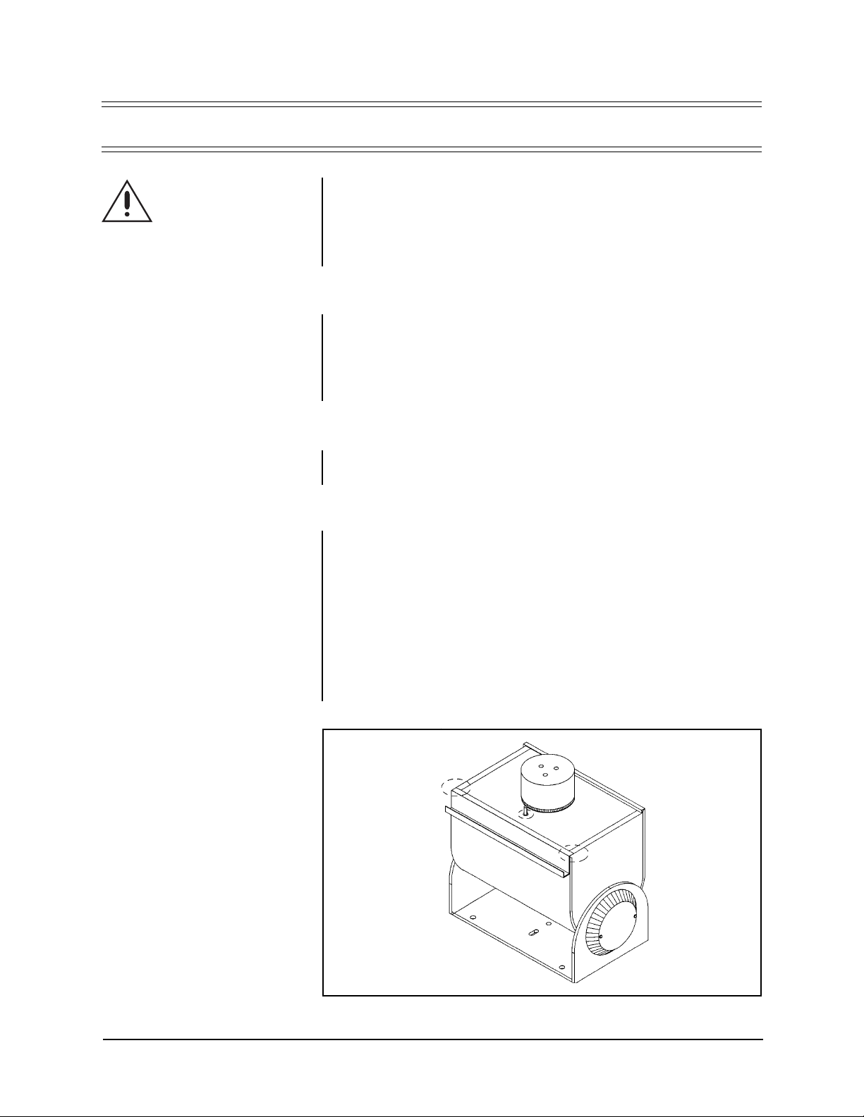
NOTE:
When mounting the pan/
tilt outdoors in the inverted position
(base up), RTV silicone sealant,
such as Dow Corning Type 732 or
equivalent, should be applied to the
areas indicated in Figure 1.
Pan/tilts in the PT1250DC Series are designed to mount onto a horizontal surface
in the upright or inverted position.
In order to ensure proper wiring and system operation of all components, it is recommended that you test the pan/tilt and the associated control equipment in your
facility before field installation. Refer to Sections 3.3 through 3.4.
3.1 MOUNTING
Attach the pan/tilt unit to a mount, following the instructions that accompany the
mount. To ensure maximum pan travel, mount the pan/tilt so that the fix ed limit stop
is directly opposite the center of the intended viewing area.
Make sure the mounting surface and the mounting method is strong enough to support four times the combined weight of the pan/tilt, enclosure, camera and lens.
3.2 CAMERA/ENCLOSURE MOUNTING
Attach the enclosure, camera and lens to the pan/tilt unit with 1/4-20 hardware (not
supplied). The enclosure, camera and lens must be correctly mounted and balanced
on the tilt table for proper operation.
3.3 WIRING
Cable distances for pan and tilt motors should not exceed the distances specified in Table A. Cable fabrication must be in accordance with Section 3.3.1, Mating Connector Assembly . The f ollowing are some recommended common installation practices.
1. Always use jack eted stranded multi-conductor interconnecting cab le between
the control and the pan/tilt unit, with additional conductors than needed for
future servicing and or additions.
2. Always use color-coded conductors for ease of wiring and to identify functions
at a later date.
3. Keep a wiring diagram with the system for later use and reference.
➛
➛
Figure 1 . Sealant Locations
➛
Pelco Manual C373M-F (10/98) 5
 Loading...