

Page 1
®
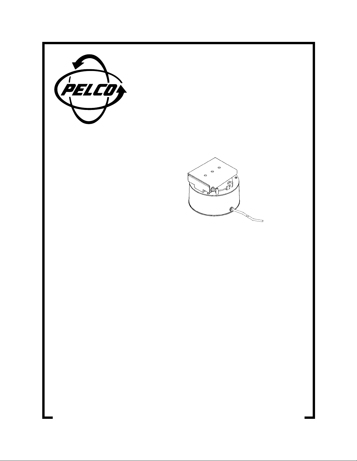
PS7 and PS7-24
Light-Duty Scanners
Installation/
Operation Manual
C350M-H (10/99)
Pelco • 3500 Pelco Way, Clovis • CA 93612-5699 USA • www.pelco.com
In North America and Canada: Tel (800) 289-9100 or FAX (800) 289-9150
International Customers: Tel +1 (559) 292-1981 or FAX +1 (559) 348-1120
Page 2

CONTENTS
LIST OF ILLUSTRATIONS
Section Page
IMPORTANT SAFEGUARDS AND WARNINGS ................................................................3
DESCRIPTION...................................................................................................................3
MODELS ....................................................................................................................3
INSTALLATION...................................................................................................................3
MOUNTING................................................................................................................4
CAMERA/ENCLOSURE MOUNTING........................................................................4
ELECTRICAL INSTALLATION ...................................................................................4
LIMIT STOP ADJUSTMENTS....................................................................................6
MAINTENANCE .................................................................................................................6
SERVICE MANUAL ....................................................................................................6
SPECIFICATIONS ..............................................................................................................7
WARRANTY AND RETURN INFORMATION ....................................................................8
Figure Page
1 PS7 and PS7-24 Wiring Diagrams.....................................................................5
2 PS7/PS7-24 Tilt and Limit Adjustments .............................................................6
LIST OF TABLES
Table Page
A Cable Distances.................................................................................................5
2 Pelco Manual C350M-H (10/99)
Page 3
IMPORTANT SAFEGUARDS AND WARNINGS
Prior to installation and use of this product, the following WARNINGS should be observed.
1. Installation and servicing should only be done by qualified service personnel and con-
form to all local codes.
2. Unless the unit is specifically marked as a NEMA Type 3, 3R, 3S, 4, 4X ,6 or 6P enclo-
sure, it is designed for indoor use only and it must not be installed where exposed to
rain and moisture.
3. The camera and lens combined weight shall not exceed 15 pounds (7 kg).
4. Only use replacement parts recommended by Pelco.
5. After replacement/repair of this unit’s electrical components, conduct a resistance
measurement between line and exposed parts to verify the exposed parts have not
been connected to line circuitry.
6. Use only installation methods and materials capable of supporting four times the com-
bined weight of the enclosure, scanner, camera and lens.
The product and/or manual may bear the follo wing marks:
This symbol indicates that dangerous voltage constituting a risk of electric shock is
present within this unit.
This symbol indicates that there are important operating and maintenance instructions
in the literature accompanying this unit.
CAUTION:
RISK OF ELECTRIC SHOCK.
DO NOT OPEN.
Please thoroughly familiarize yourself with the information in this manual prior to installation
and operation.
DESCRIPTION
The PS7 and PS7-24 “mini” scanners are light-duty indoor scanning units designed to operate with a maximum load of 15 pounds (7 kg.).
The PS7 is a 120 VAC continuous-duty scanner. The PS7-24 is a 24 VAC scanner capable
of either automatic or manual operation when used with a remote control unit or continuousduty operation when voltage is supplied directly to the scanner. External limit stops allow for
pan rotation up to 320 degrees.
MODELS
PS7 Light-duty “mini” scanner, 120 VAC (UL)
PS7-24 Light-duty “mini” scanner, 24 VAC (CE, UL)
INSTALLATION
The following parts are supplied:
1 PS7 Scanner with six-foot cord or
PS7-24 Scanner with eight-foot cable
1 Adapter plate
3 10-32 mounting screws
3 Internal tooth lock washer
1 Allen hex key
Pelco Manual C350M-H (10/99) 3
Page 4

CAUTION:
The
PS7 Series Scanner
is designed to
operate upright or inverted.
Do not mount horizontally.
MOUNTING
Make sure the mounting surface can support four times the combined weight of the scanner
and the camera and lens or enclosure, camera, and lens. Refer to the manuals for your enclosure, camera, and lens for the weights of those units. The weight of the camera and lens
or enclosure, camera and lens must not exceed 15 pounds (7 kg).
To mount the scanner directly to a solid surface, attach the adapter plate to the scanner
with the three 10-32 mounting screws provided. Fasten the adapter plate to the solid surface using four number 10 scre ws or other suitable fasteners.
If you use a wall, or ceiling/pedestal mount, follow the instructions that are provided with the
mount and then attach the scanner to the mount with the three 10-32 mounting screws supplied.
CAMERA/ENCLOSURE MOUNTING
To mount a camera or enclosure, lift the tilt table. Center (balance) the camera and lens or
enclosure, camera and lens load on the tilt table. Adjust the position as needed to align the
mounting holes. A 1/4-20 hex head bolt (not supplied) is required to mount the camera to
the tilt table. Secure the load to the tilt table. Manually adjust tilt table to desired angle and
tighten. Make all necessary electrical connections. To wire the camera and lens or camera
enclosure, refer to the manuals for that equipment.
ELECTRICAL INSTALLATION
This section provides instructions for wiring the scanner only.
PS7
The PS7 is supplied with a six-foot line cord. Plug the line cord directly into a standard
120 VA C outlet.
PS7-24
Remote Control - Connect the eight-foot cable to a terminal strip. Run a matching
cable from the terminal strip to the scanner control. Refer to the wiring diagram in Figure 1.
For inverted operation, reverse the left and right wires.
Refer to Table A for cable distances. The maximum distance is B. If you are using a relay
box, the maximum distance is A plus B.
Continuous-Duty Operation - Connect the COMMON and AUTO wires to a 24 VAC
power supply. Ground the green wire to the closest available ground. Refer to the wiring diagram in Figure 1. Refer to distance B in Table A for cable distances.
4 Pelco Manual C350M-H (10/99)
Page 5

Table A. Cable Distances*
Model (AWG) Distance “A” Distance “B”
Wire Size Maximum Maximum
PS7-24 20 5,800 ft (1,768 m) 745 ft (227 m)
18 8,250 ft (2,515 m) 1,185 ft (361 m)
16 13,000 ft (3,962 m) 1,885 ft (574 m)
*Cable distances are calculated with the motor running and
assuming a 10% voltage drop in the cable.
NOTE:
Conductors are for left and right functions, motor common,
and safety ground.
CAUTION:
The input voltage for the PS7-24 must not
exceed 28 volts or damage to the motor may occur.
A B
PS7-24
MPS524DT/ RB24
MPTAZ24DT
120 VAC POWER SOURCE
PS7 WIRING DIAGRAM
PS7-24 WIRING DIAGRAM
Figure 1. PS7 and PS7-24 Wiring Diagrams
Pelco Manual C350M-H (10/99) 5
Page 6

WARNING:
Do
not operate the
scanner without
limit stops. Do not attempt to
adjust the limit stops while
the unit is operating.
Personal injury or damage
to the unit may result. Do not
remove or reposition the
fixed limit stop on the
scanner. DAMAGE WILL
OCCUR.
LIMIT STOP ADJUSTMENTS
To set pan limit stops, perform the following steps. Refer to Figure 2.
1. Loosen the pan limit stops.
2. Operate the scanner. Pan the unit to the right until the desired right pan limit is
reached.
3. Move the right pan limit stop until it touches the pan limit switch actuator. Push the
stop against the actuator until it clicks, indicating that the limit switch has opened.
Lock the stop in place.
4. Pan the unit to the desired left position. Adjust the left pan limit stop as described in
step 3.
5. Pan left and right to both limit stops and check for exact positioning. Tighten both stops
securely.
MAINTENANCE
Under normal operating conditions and usage, maintenance of this equipment is not necessary. Scanners in the PS7 Series require no lubrication, and the motors are both clutch and
impedance protected from overload. The outside of the scanner may be cleaned by wiping
with a dry cloth or spraying with clean air pressure. Do not use spray cleaners or water.
SERVICE MANUAL
If you need to service your unit, obtain a service manual in one of the following ways:
• Go to Pelco’s web site at ftp://www.pelco.com and find service manual C350SM.
• Contact Pelco’s Literature Department and request service manual C350SM.
Figure 2. PS7/PS7-24 Tilt and Limit Adjustments
6 Pelco Manual C350M-H (10/99)
Page 7

SPECIFICATIONS
GENERAL
Construction: Aluminum with injection-molded plastic housing
Finish: Gray polyester powder coat
Environment: Indoor; 35° to 140°F (2° to 60°C)
Weight: 4 lb (1.80 kg)
MECHANICAL
Pan: 0-320° movement in horizontal plane
Speed: 6°/sec ±.5° maximum load 15 lb (6.8 kg)
Operation: Upright or inverted
Bearings: Heavy-duty needle bearings on output shaft
Overload
Protection: Slip clutch on motor
ELECTRICAL
Input Voltage
PS7: 120 VAC
PS7-24: 24 VA C
Power Requirements
PS7: 60 mA (6.9 vA)
PS7-24: 160 mA (3.8 vA)
Connectors
PS7: 6-ft (1.82 m) AC power cord
PS7-24: 8-ft (2.43 m) cable with spade lugs
Motors: Two-phase induction type, continuous duty, instantaneous reversing
Limit Switches: Pan – 5 amp; external adjustment
Conductors: 5, unshielded (functions: left, right, auto, motor common, safety ground)
Braking: Dynamic for instantaneous stopping
RATINGS
NEMA 1
(Design and product specifications subject to change without notice.)
Pelco Manual C350M-H (10/99) 7
Page 8

WARRANTY AND RETURN INFORMATION
WARRANTY
Pelco will repair or replace, without charge, any merchandise proved defective in material
or workmanship for a period of one year after the date of shipment.
Exceptions to this warranty are as noted below:
• Five years on FT/FR8000 Series fiber optic products.
• Three years on Genex® Series products (multiplexers, server, and keyboard).
• Three years on Camclosure® and fixed camera models, except the CC3701H-2,
CC3701H-2X, CC3751H-2, CC3651H-2X, MC3651H-2, and MC3651H-2X camera
models, which have a five-year warranty.
• Two years on standard motorized or fixed focal length lenses.
• Two years on Legacy®, CM6700/CM6800/CM9700 Series matrix, and DF5/DF8 Series
fixed dome products.
• Two years on Spectra®, Esprit®, ExSite™, and PS20 scanners, including when used in
continuous motion applications.
• Two years on Esprit® and WW5700 Series window wiper (excluding wiper blades).
• Eighteen months on DX Series digital video recorders, NVR300 Series network video
recorders, and Endura™ Series distributed network-based video products.months on DX
Series digital video recorders, NVR300 Series network video recorders, Endura™ Series
distributed network-based video products, and TW3000 Series twisted pair transmission
products.
• One year (except video heads) on video cassette recorders (VCRs). Video heads will be
covered for a period of six months.
• Six months on all pan and tilts, scanners or preset lenses used in continuous motion
applications (that is, preset scan, tour and auto scan modes).
Pelco will warrant all replacement parts and repairs for 90 days from the date of Pelco
shipment. All goods requiring warranty repair shall be sent freight prepaid to Pelco, Clovis,
California. Repairs made necessary by reason of misuse, alteration, normal wear, or
accident are not covered under this warranty.
Pelco assumes no risk and shall be subject to no liability for damages or loss resulting
from the specific use or application made of the Products. Pelco’s liability for any claim,
whether based on breach of contract, negligence, infringement of any rights of any party
or product liability, relating to the Products shall not exceed the price paid by the Dealer to
Pelco for such Products. In no event will Pelco be liable for any special, incidental or
consequential damages (including loss of use, loss of profit and claims of third parties)
however caused, whether by the negligence of Pelco or otherwise.
The above warranty provides the Dealer with specific legal rights. The Dealer may also
have additional rights, which are subject to variation from state to state.
If a warranty repair is required, the Dealer must contact Pelco at (800)289-9100 or
(559) 292-1981 to obtain a Repair Authorization number (RA), and provide the following
information:
1. Model and serial number
2. Date of shipment, P.O. number, Sales Order number, or Pelco invoice number
3. Details of the defect or problem
If there is a dispute regarding the warranty of a product which does not fall under the
warranty conditions stated above, please include a written explanation with the product
when returned.
Method of return shipment shall be the same or equal to the method by which the item
was received by Pelco.
RETURNS
In order to expedite parts returned to the factory for repair or credit, please call the factory
at (800) 289-9100 or (559) 292-1981 to obtain an authorization number (CA number if
returned for credit, and RA number if returned for repair).
All merchandise returned for credit may be subject to a 20% restocking and refurbishing
charge.
Goods returned for repair or credit should be clearly identified with the assigned CA or RA
number and freight should be prepaid. Ship to the appropriate address below.
If you are located within the continental U.S., Alaska, Hawaii or Puerto Rico, send goods
to:
If you are located outside the continental U.S., Alaska, Hawaii or Puerto Rico and are
instructed to return goods to the USA, you may do one of the following:
If the goods are to be sent by a COURIER SERVICE, send the goods to:
If the goods are to be sent by a FREIGHT FORWARDER, send the goods to:
Service Department
Pelco
3500 Pelco Way
Clovis, CA 93612-5699
Pelco
3500 Pelco Way
Clovis, CA 93612-5699 USA
Pelco c/o Expeditors
473 Eccles Avenue
South San Francisco, CA 94080 USA
Phone: 650-737-1700
Fax: 650-737-0933
REVISION HISTORY
Manual # Date Comments
C350M-H 10/99 Rev. H. Revised mounting and installation instructions. Moved exploded assembly diagram and parts list to new
maintenance/service manual (C350SM). Updated manual to new f ormat.
® Pelco, the Pelco logo, Spectra, Esprit, Genex, Legacy, and Camclosure are registered trademarks of Pelco.
™ Endura and ExSite are trademarks of Pelco. © Copyright 1999, Pelco. All rights reserved.
8 Pelco Manual C350M-H (10/99)
 Loading...