

Page 1
C360SM (10/99)
PS30A and PS30-24
Scanners
®
300 W. Pontiac Way,
Clovis, CA 93612-5699
USA
In North America & Canada:
Tel (800) 289-9100
FAX (800) 289-9150
DataFAX (800) 289-9108
International Customers:
Tel +1 (559) 292-1981
FAX +1 (559) 348-1120
DataFAX +1 (559) 292-0435
Pelco Online
http://www.pelco.com
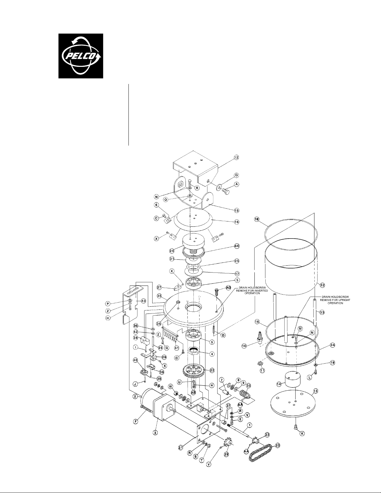
This maintenance/service manual consists of an exploded assembly diagram and parts lists. Use
this manual when ordering replacement parts for PS30A/PS30-24 Scanners.
MAINTENANCE
Under normal operating conditions and usage, maintenance of this equipment is not necessary.
The PS30A and PS30-24 Scanners require no lubrication, and the motors are both clutch and
impedance protected from overload. The outside of the scanner can be cleaned by wiping with a
dry cloth or spraying with clean air pressure. Do not use spray cleaners or water.
EXPLODED ASSEMBLY DIAGRAM
Figure 1. PS30A/PS30-24
Exploded Assembly Diagram
Page 2

Table A. Mechanical Parts List
Item Qty Description Part Number
1 1 Gear train shaft 1754064COMP
2 1 Motor, 24 VAC (PS30-24) 5708008
Motor, 120 VAC (PS30A) 1758008
3 1 Motor gear head 1758009
4 1 Spindle nut 2504012COMP
5 2 Pan spindle bearing 2506000
6 3 Limit stop 5801006
7 1 Bearing 5806005
8 2 Bearing cage 776001
9 4 Bearing washer 776002
10 1 Gland EH300010003
11 1 Nut for EH300010003 gland EH300010004
12 1 Top bracket EM224168COMP
13 1 Flange PM102A4196COMP
14 1 Mounting block PS204153COMP
15 1 Lower tilt bracket PS204160COMP
16 1 Dust cover PS204162COMP
17 1 Drag disk PS3010000
18 2 O-ring PS3010001
19 5 Thread sealing washer PS3010002
20 1 Drive chain PS301005COMP
21 1 Motor plate weld assembly PS301007WA
22 1 Worm gear PS304001COMP
23 1 Gear shaft sprocket PS304005COMP
24 1 Spindle PS304006COMP
25 1 Spindle spacer PS304008COMP
26 1 Limit switch shaft PS304009COMP
27 1 Limit arm PS304010COMP
28 1 Limit switch bracket PS304011COMP
29 1 Motor shaft sprocket PS304012COMP
30 1 Worm PS304013COMP
31 1 Spring washer PS304015COMP
32 1 Cover PS304102COMP
33 3 Spacer PS304103COMP
34 1 Bottom plate PS304104COMP
35 1 Top plate PS304110COMP
36 2 Friction disk limit PS710001
37 1 Bushing, 1/4-inch PT250010005
38 1 Switch SWI11-314
39 2 Switch SWI1SM1
40 2 Switch actuator with insulator SWIJS138B
41 1 Terminal strip, 7-pin TRS2007
42 1 Spring washer TV10000
43 1 Heat sink (PS30-24 only) PS304016COMP
44 1 Spindle seal PS3010003
Page 3

T able B. Hardware Parts List
Item Qty Description Part Number
A 2 Bolt, 3/8-16 x .625-inch ZH3/816X.625CH
B 3 Bolt, 1/4-20 x .625-inch ZH1/420X.625CH
C 3 Screw, 6-32 x .375-inch, pan head, Phillips ZH6-32X.375SPP
D 3 Set screw, 10-32 x .75-inch ZH10-32X.750S
E 4 Allen screw, 10-32 x .5-inch ZH10-32X.500CS
F 4 Screw, 8-32 x 2.25-inch, pan head ZH8-32X2.25CRS
G 1 Screw, 6-32 x .25-inch, pan head, Phillips ZH6-32X.250SPP
H 5 Allen screw, 6-32 x .375-inch ZH6-32X.375CS
I 2 Screw, 2-56 x .75-inch, pan head, Phillips ZH2-56X.750SPS
J 4 Screw, 2-56 x .437-inch, pan head, Phillips ZH2-56X.437SPP
K 3 Screw, 1/4-20 x .75-inch, flat head ZH1/4-20X.750CFS
L 3 Screw, 10-32 x .75-inch, pan head, Phillips ZH10-32X.750SPP
M 2 Allen bolt, 1/4-20 x .625-inch ZH1/420X.625CH
N 5 Split lock washer, .25-inch ZH1/4LWSSL
O 3 Flat washer, .1875-inch ZH260X562X65C
P 2 Flat washer, #8 ZH188X435X60C
Q 2 Flat washer, .375-inch ZH377X880X78
R 8 Flat washer, #10 ZH204X436X60C
S 4 Split lock washer, #8 ZH8LWSSL
T 4 Nut, 8-32 ZH8-32NUTSH
U 3 Split lock washer, #6, ZH6LWSSL
V 4 Split lock washer, #10 ZH10LWSSL
W 1 Nylon lock nut, 1/4-28 58010007
X 3 Set screw, 6-32 x .1875-inch ZH6-32X.187S
Y 1 Set screw, 10-32 x .1875-inch ZH10-32X.187S
Z 3 Internal tooth lock washer, #6 ZH6LWSIS
AA 2 Roll pin, .09375-inch x .5-inch ZHPIN3/32X1/2R
AB 2 Dowel pin .125-inch x .5-inch 15510003
AC 1 Connector mating assembly, 9-pin (not shown) 1751000COMP
AD 2 Allen screw, 10-32 x .375-inch ZH10-32X.375CS
WIRING DIAGRAMS AND SCHEMATICS
REMOTE CONTROL OPERATION
QTY SYMBOL DESCRIPTION PART NUMBER
1 C1 CAPACITOR, CAPU0001.8/250
1.8 µF/250V
2 C2-C4 CAPACITOR, CAPU000.05/500
.05 µF/500V
1 M1 MOTOR 1758008
1 R1 RESISTOR, RES012.0-8
12 OHM/8 W
CONTINUOUS-DUTY OPERATION
2 S1-S2 SWITCH SWI1SM1
1 S3 SWITCH SWI11-314
Figure 2. PS30A Schematic and Wiring Diagrams
Page 4

REMOTE CONTROL OPERATION
CONTINUOUS-DUTY OPERATION
Figure 3. PS30-24 Schematic and Wiring Diagrams
QTY SYMBOL DESCRIPTION PART NUMBER
2 C1-C2 CAPACITOR, CAPU0015.0/100N
15 µF/100V
2 C3-C4 CAPACITOR, CAPU000.05/500
.05 µF/500V
1 M1 MOTOR 5708008
1 R1 RESISTOR, RES010.0-.5
10 OHM, 1/2 W
2 S1-S2 SWITCH SWI1SM1
1 S3 SWITCH SWI11-314
WARRANTY AND RETURN INFORMATION
WARRANTY
Pelco will repair or replace, without charge, any merchandise proved defective in material or workmanship for a period of one year after the date of
shipment. Exceptions to this warranty are as noted below:
• Three years on Genex™ Series (multiplexers, server, and keyboard).
• Two years on all standard motorized and fixed focal length lenses.
• Two years on Esprit™, Legacy®, Intercept®, PV1000 Series, CM6700/
CM8500/CM9500/CM9750/CM9760 Matrix, Spectra®, DF5 Series and DF8
Fixed Dome products.
• Two years on WW5700 series window wiper (excluding wiper blades).
• Two years on cameras.
• Six months on all pan and tilts, scanners or preset lenses used in continuous
motion applications (that is, preset scan, tour and auto scan modes).
Pelco will warrant all replacement parts and repairs for 90 da ys from the date
of Pelco shipment. All goods requiring warranty repair shall be sent freight
prepaid to Pelco, Clovis, California. Repairs made necessary by reason of
misuse, alteration, normal wear, or accident are not covered under this warranty.
Pelco assumes no risk and shall be subject to no liability for damages or loss
resulting from the specific use or application made of the Products. Pelco’s
liability for any claim, whether based on breach of contract, negligence, infringement of any rights of any party or product liability, relating to the Products shall not exceed the price paid by the Dealer to Pelco f or such Products .
In no event will Pelco be liable for any special, incidental or consequential
damages (including loss of use, loss of profit and claims of third parties) however caused, whether by the negligence of Pelco or otherwise.
The above warranty provides the Dealer with specific legal rights. The Dealer
may also have additional rights, which are subject to variation from state to state.
REVISION HISTORY
Manual # Date Comments
C360SM 10/99 Original version.
If a warranty repair is required, the Dealer must contact Pelco at (800) 2899100 or (559) 292-1981 to obtain a Repair Authorization number (RA), and
provide the following information:
1. Model and serial number
2. Date of shipment, P .O. number , Sales Order n umber , or P elco inv oice number
3. Details of the defect or problem
If there is a dispute regarding the warranty of a product which does not fall
under the warranty conditions stated above, please include a written explanation with the product when returned.
Ship freight prepaid to: Pelco
Method of return shipment shall be the same or equal to the method by which
the item was received by Pelco.
RETURNS
In order to expedite parts returned to the factory for repair or credit, please
call the factory at (800) 289-9100 or (559) 292-1981 to obtain an authorization number (CA number if returned for credit, and RA number if returned for
repair). Goods returned for repair or credit should be clearly identified with
the assigned CA/RA number and freight should be prepaid. All merchandise
returned for credit may be subject to a 20% restocking and refurbishing charge.
Ship freight prepaid to: Pelco
300 West Pontiac Way
Clovis, CA 93612-5699
300 West Pontiac Way
Clovis, CA 93612-5699
®Pelco and the Pelco logo are registered trademarks of Pelco. © Copyright 1999, Pelco. All rights reserved.
 Loading...