

Page 1
®
PS20 Medium-Duty
Indoor/Outdoor Scanner
Installation/
Operation Manual
C361M-A (8/02)
Pelco World Headquarters • 3500 Pelco Way, Clovis, CA 93612-5699 USA • www.pelco.com
USA & Canada: Tel: 800/289-9100 • Fax: 800/289-9150
International: Tel: 1-559/292-1981 • Fax: 1-559/348-1120
Page 2

IMPORTANT SAFEGUARDS AND WARNINGS
Prior to installation and use of this product, the following WARNINGS should be observed.
1. Installation and servicing should only be done by qualified service personnel and
conform to all local codes.
2. Installation shall be done in accordance with all local and national elecctrical and
mechanical codes using only approved materials.
3. Unless the unit is specifically marked as a NEMA Type 3, 3R, 3S, 4, 4X, 6 or 6P
enclosure, it is designed for indoor use only and it must not be installed where
exposed to rain and moisture.
4. The camera and lens combined weight shall not exceed 35 pounds (16 kg).
5. Only use replacement parts recommended by Pelco.
6. After replacement/repair of this unit’s electrical components, conduct a resistance
measurement between line and exposed parts to verify the exposed parts have not
been connected to line circuitry.
7. Use only installation methods and materials capable of supporting four times the
combined weight of the enclosure, scanner, camera, and lens.
8. An ALL-POLE MAINS SWITCH with a contact separation of at least 3 mm in each
pole shall be incorporated in the electrical installation of the building.
9. For 24 VAC models only, use a UL Listed, Class 2 power source.
DESCRIPTION
INSTALLATION
NOTE:
compartment shall be provided in which mains supply
connections are to be made
and shall be such that these
connections are capable of
being readily made and inspected without disturbing
the wiring or the apparatus
after the unit is installed.
A terminal box or
The PS20 Series scanner is a medium-duty indoor/outdoor unit designed to operate with a
maximum load of 35 pounds (16 kg). The scanner features stepper motor technology, three
selectable speed settings, easy-to-adjust limit stops, and pan rotation of 380 degrees.
The PS20 scanner is capable of continuous and random operation when connected directly
to a power source. If a Pelco MPTAZ Series control is used, the scanner can operate
continuously, randomly, and manually.
MODELS
PS20 Medium-duty scanner, 120 VAC
PS20-24 Medium-duty scanner, 24 VAC
PS20/230 Medium-duty scanner, 230 VAC
The PS20 scanner can be mounted to any flat surface in an upright or inverted position. If
the scanner is to be attached to a wall/ceiling/pedestal mount, follow the instructions
provided with the mount.
Installation requires a mounting surface or mount with a center feed through hole. Use a
suitable wiring compartment/terminal box for connection with the AC mains supply and
attach the PS20 scanner directly to the mounting surface.
2 Pelco Manual C361M-A (8/02)
Page 3
PREPARE MOUNTING SURFACE
SCANNER
FEED THRU
HOLE
NOTE:
Minimum recommendation for mounting
hardware is 1/4-20 X 5/8 Hex
Head Bolt Stainless Steel,
1/4" Split Lock Washer Stainless Steel, and 1/4" Flat
Washer Stainless Steel with
1" Outer Diameter.
1. Determine the mounting location. Make sure the mounting surface can support four
times the combined weight of the scanner and the camera and lens or enclosure,
camera, and lens. Refer to the manuals for your enclosure, camera, and lens for the
weights of those units.
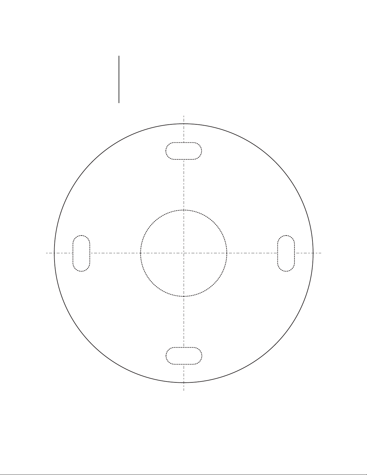
2. If mounting directly to a flat surface, use Figure 1 as a template and mark the bolt and
cable/wire feedthrough positions onto the installation surface. Prepare the mounting
surface and pull cable/wiring for the scanner.
BOLT
HOLE
BOLT
HOLE
SCANNER
FEED THRU
HOLE
BOLT
HOLE
Figure 1. PS20 Surface Mount Template
BOLT
HOLE
00814
Pelco Manual C361M-A (8/02) 3
Page 4

WIRING
Make electrical connections as required for scanner
operation. If required use the wire nuts (provided).
Cable distances should not exceed the distances
specified in Table A.
Refer to the following wiring diagrams (Figure 3)
and select the correct diagram for your installation.
GLAND AND WIRING
ATTACHMENT
Figure 2. Bottom View, Wire
Attachment
120V MODEL
WITH CONTROLLER
CABLE
FROM
SCANNER
WITHOUT CONTROLLER
CABLE
FROM
SCANNER
CABLE
FROM
SCANNER
BLU
BRN
ORG
RED
WHT
GRN/YEL
BLK
WHT
GRN/YEL
BLK
RED
BLU
BRN
ORG
RANDOM MODE
WHT
GRN/YEL
BLK
RED
ORG
BRN
BLU
24V MODEL
WITH CONTROLLER
COMMON
LEFT
RIGHT
AUTO
120 AC LO
GROUND
120 AC HI
CABLE
FROM
SCANNER
BLU
BRN
ORG
RED
WHT
GRN/YEL
BLK
COMMON
LEFT
RIGHT
AUTO
24 AC LO
GROUND
24 AC HI
WITHOUT CONTROLLER
120 AC LO
GROUND
120 AC HI
AUTO
120 AC LO
NOT USED
NOT USED
CABLE
FROM
SCANNER
WHT
GRN/YEL
BLK
RED
BLU
BRN
ORG
24 AC LO
GROUND
24 AC HI
AUTO
120 AC LO
NOT USED
NOT USED
RANDOM MODE
120 AC LO
GROUND
120 AC HI
CABLE
FROM
SCANNER
WHT
GRN/YEL
BLK
RED
ORG
BRN
BLU
24 AC LO
GROUND
24 AC HI
Figure 3. Wiring Diagrams - 120V, 24V and 230V Models
Table A. Maximum Operating Distances
Model 20 AWG 18 AWG 16 AWG
PS20 2,300 ft 3,700 ft 5,900 ft
PS20-24 5,600 ft 9,000 ft 14,300 ft
PS20/23 1,400 ft 2,300 ft 3,600 ft
(0.5 mm2) (1.0 mm2) (1.5mm2)
(701 m) (1,127 m) (1,798 m)
(1,706 m) (2,743 m) (4,368 m)
(426 m) (701 m) (1,097 m)
230V MODEL
WITH CONTROLLER
CABLE
FROM
SCANNER
WITHOUT CONTROLLER
CABLE
FROM
SCANNER
CABLE
FROM
SCANNER
WHT
BLK
ORG
RED
BLU
GRN/YEL
BRN
BLU
GRN/YEL
BRN
RED
WHT
ORG
BLK
RANDOM MODE
BLU
GRN/YEL
BRN
RED
BLK
ORG
WHT
COMMON
LEFT
RIGHT
AUTO
230 AC LO
GROUND
230 AC HI
230 AC LO
GROUND
230 AC HI
AUTO
120 AC LO
NOT USED
NOT USED
230 AC LO
GROUND
230 AC HI
00815
4 Pelco Manual C361M-A (8/02)
Page 5

MOUNTING
12
Attach the scanner to a flat surface or compatible wall/ceiling/pedestal mount using four
bolts (not provided).
CAMERA/ENCLOSURE MOUNTING
1. Center (balance) the camera and lens, or enclosure, camera, and lens load on the tilt
table. Adjust the positioning as needed to align the mounting holes.
2. Attach the camera or enclosure to the tilt table with two 1/4-20 hex head bolts (not
supplied).
3. Position the tilt table at the desired angle and tighten the manual tilt adjustment bolts
(refer to Figure 3) to secure the table.
4. Make all camera, enclosure, and lens connections. Refer to the manuals supplied with
the equipment. Leave enough slack in the cable/wiring so that the camera, enclosure,
and lens connections do not interfere with the operation of the scanner.
SPEED SETTING
The PS20 Series scanner has selectable speed settings for 3 degrees, 6 degrees, and 12
degrees per second. The default speed setting is 6 degrees per second. To decrease or
increase the speed setting do the following:
1. Loosen the screw that secures the speed setting cover. The cover is located on the
side of the scanner (refer to Figure 3).
2. Remove the speed setting cover.
3. Set the switch to the desired speed setting.
4. Replace the cover and tighten the screw.
TILT TABLE
MANUAL TILT
ADJUSTMENT
BOLT
3 612
SPEED
SETTINGS
LIMIT STOP
Figure 4. Scanner Adjustments and Settings
00813
Pelco Manual C361M-A (8/02) 5
Page 6

LIMIT STOP ADJUSTMENT
To set pan limit stops, perform the following steps:
1. Loosen the right and left limit stops.
2. Operate the scanner. Pan the unit to the right until the desired right pan limit is
reached.
3. Move the right limit stop to the selected position and secure in place.
4. Pan the unit to the desired left position. Slide the left limit stop to the selected position
and secure in place.
5. Pan left and right to both limit stops to check for exact positioning. Tighten both stops
securely.
To pan the scanner 380 degrees, remove one limit stop from the scanner. Only one limit
stop is removable. The other limit stop is fixed to the scanner; it can be adjusted but not
removed.
6 Pelco Manual C361M-A (8/02)
Page 7

SPECIFICATIONS
MECHANICAL
Pan: 0-380° movement in horizontal plane
Speed: 3°, 6°, or 12° per sec ±.5°
Maximum Load: 35 lb (16 kg) centered
Operation: Upright or inverted
Bearings: Heavy-duty ball bearings
Overload Protection: Thermal protected
ELECTRICAL
Input Voltage
PS20: 120 VAC
PS20-24: 24 VAC
PS20/230: 230 VAC
Power Requirements
PS20: 0.175 A (20 vA)
PS20-24: 0.600 A (15 vA)
PS20/230: 0.130 A (30 vA)
Connectors: Wire nuts provided
Motors: Stepper motor, continuous duty, instantaneous reversing
Limit Switches: Auto scan switching, external adjustment
Conductors: 7, unshielded (functions: left, right, auto, common, safety ground,
GENERAL
Construction: Aluminum
Finish: Gray polyester powder coat
Environment: Indoor/outdoor; -10° to 120°F (-23° to 49°C)
Unit Weight: 9.9 lb (4.5 kg)
AC Line, AC Neutral)
Pelco Manual C361M-A (8/02) 7
Page 8

REGULATORY NOTICES
This equipment has been tested and found to comply with the limits of a Class B digital
device, pursuant to part 15 of the FCC rules. These limits are designed to provide
reasonable protection against harmful interference in a residential installation. This
equipment generates, uses, and can radiate radio frequency energy and, if not installed
and used in accordance with the instructions, may cause harmful interference to radio
communications. However there is no guarantee that the interference will not occur in a
particular installation. If this equipment does cause harmful interference to radio or
television reception, which can be determined by turning the equipment off and on, the user
is encouraged to try and correct the interference by one or more of the following measures:
• Reorient or relocate the receiving antenna.
• Increase the separation between the equipment and the receiver.
• Connect the equipment into an outlet on a circuit different from that to which the re-
ceiver is connected.
• Consult the dealer or an experienced radio/TV technician for help.
WARRANTY AND RETURN INFORMATION
WARRANTY
Pelco will repair or replace, without charge, any merchandise proved defective in
material or workmanship for a period of one year after the date of shipment. Exceptions to this warranty are as noted below:
• Five years on Pelco manufactured cameras (CC3500/CC3600/CC3700 and
MC3500/MC3600/MC3700 Series); two years on all other cameras.
• Three years on Genex® Series (multiplexers, server, and keyboard).
•Two years on cameras and all standard motorized or fixed focal length lenses.
•Two years on Legacy®, Camclosure® Camera Systems, CM6700/CM6800/
CM8500/CM9500/CM9740/CM9760 Matrix, DF5 and DF8 Series Fixed Dome
products.
•Two years on Spectra®, Esprit®, and PS20 Scanners, including when used in
continuous motion applications.
•Two years on Esprit and WW5700 series window wiper (excluding wiper blades).
• Eighteen months on DX Series digital video recorders.
• One year (except video heads) on video cassette recorders (VCRs). Video heads
will be covered for a period of six months.
• Six months on all pan and tilts, scanners or preset lenses used in continuous
motion applications (that is, preset scan, tour and auto scan modes).
Pelco will warrant all replacement parts and repairs for 90 days from the date of
Pelco shipment. All goods requiring warranty repair shall be sent freight prepaid
to Pelco, Clovis, California. Repairs made necessary by reason of misuse,
alteration, normal wear, or accident are not covered under this warranty.
Pelco assumes no risk and shall be subject to no liability for damages or loss
resulting from the specific use or application made of the Products. Pelco’s liability
for any claim, whether based on breach of contract, negligence, infringement of
any rights of any party or product liability, relating to the Products shall not exceed
the price paid by the Dealer to Pelco for such Products. In no event will Pelco be
liable for any special, incidental or consequential damages (including loss of use,
loss of profit and claims of third parties) however caused, whether by the negligence
of Pelco or otherwise.
The above warranty provides the Dealer with specific legal rights. The Dealer may
also have additional rights, which are subject to variation from state to state.
If a warranty repair is required, the Dealer must contact Pelco at (800) 289-9100
or (559) 292-1981 to obtain a Repair Authorization number (RA), and provide the
following information:
1. Model and serial number
2. Date of shipment, P.O. number, Sales Order number, or Pelco invoice number
3. Details of the defect or problem
If there is a dispute regarding the warranty of a product which does not fall under
the warranty conditions stated above, please include a written explanation with
the product when returned.
Method of return shipment shall be the same or equal to the method by which the
item was received by Pelco.
RETURNS
In order to expedite parts returned to the factory for repair or credit, please call
the factory at (800) 289-9100 or (559) 292-1981 to obtain an authorization number (CA number if returned for credit, and RA number if returned for repair).
All merchandise returned for credit may be subject to a 20% restocking and
refurbishing charge.
Goods returned for repair or credit should be clearly identified with the assigned
CA or RA number and freight should be prepaid. Ship to the appropriate address
below.
If you are located within the continental U.S., Alaska, Hawaii or Puerto Rico:
Service Department
Pelco
3500 Pelco Way
Clovis, CA 93612-5699
If you are located outside the continental U.S., Alaska, Hawaii or Puerto Rico:
Intermediate Consignee Ultimate Consignee
American Overseas Air Freight Pelco
320 Beach Road 3500 Pelco Way
Burlingame, CA 94010 Clovis, CA 93612-5699
USA USA
REVISION HISTORY
Manual # Date Comments
C361M 6/01 Original version.
C361M-A 8/02 Revised installation instructions. Added certifications.
® Pelco, the Pelco logo, Spectra, Genex, Esprit, Camclosure, and Legacy are registered trademarks of Pelco. © Copyright 2002, Pelco.
All rights reserved.
8 Pelco Manual C361M-A (8/02)
 Loading...