

Page 1
POE1XT
Single-Port PoE
Gigabit Extender
User Manual
C3933M (8/13)
Page 2

Contents
Important Safety Instructions ........................................................................................................................................................ 3
Important Notices ......................................................................................................................................................................... 3
Regulatory Notices ................................................................................................................................................................ 3
Radio and Television Interference ................................................................................................................................. 3
ESD Warning ........................................................................................................................................................................ 4
Warranty ....................................................................................................................................................................................... 4
Specifications ............................................................................................................................................................................... 4
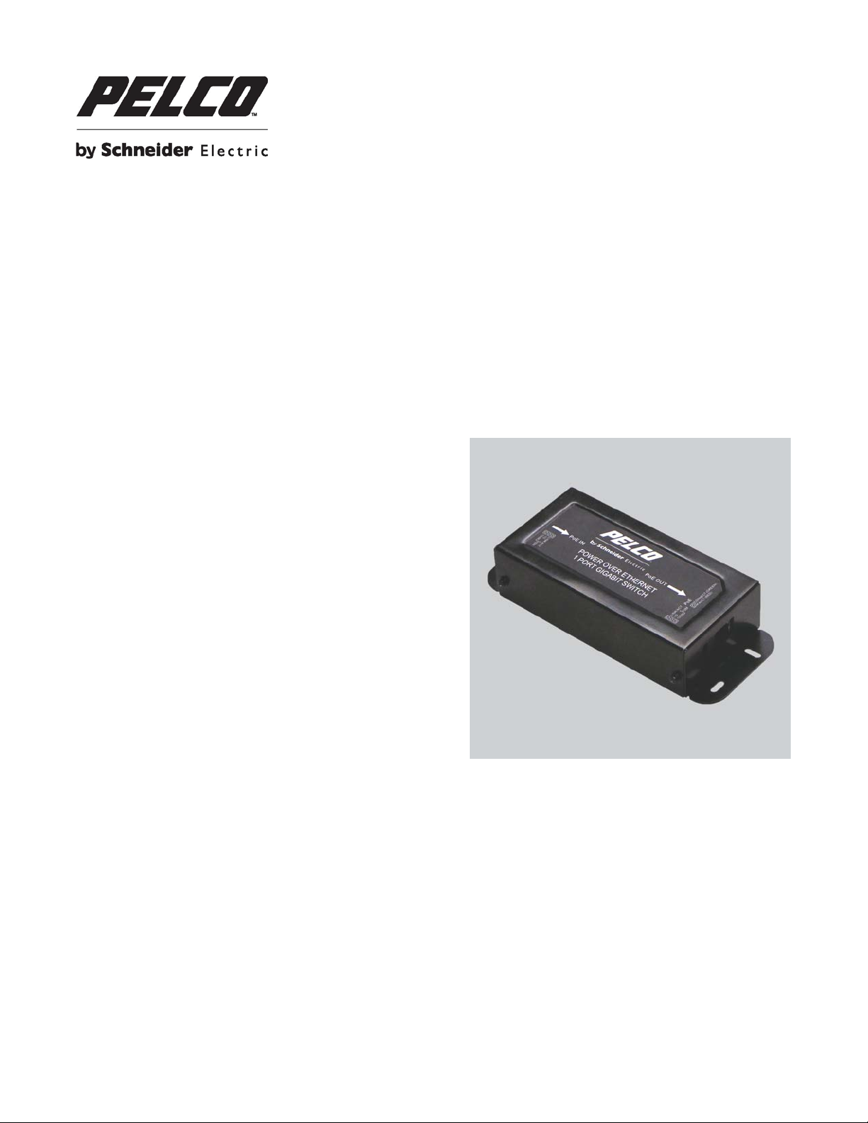
POE1XT Extender Introduction .................................................................................................................................................... 4
Installation Instructions ................................................................................................................................................................. 5
Extender Operation ...................................................................................................................................................................... 5
Frequently Asked Questions ........................................................................................................................................................ 5
What are the benefits to using PoE? ..................................................................................................................................... 5
Why am I limited to 100 meters? ........................................................................................................................................... 5
What is the difference between IEEE802.3af and IEEE802.3at? .......................................................................................... 6
Do I need a special configuration for my network?................................................................................................................ 6
Where should I install my PoE Extender? ............................................................................................................................. 6
Can I connect multiple POE EXTENDERs to extend my reach beyond 200 meters? ........................................................... 6
Can I use the POE1XT with equipment that is not PoE ready? ............................................................................................ 6
Troubleshooting ........................................................................................................................................................................... 6
Power-up Sequence: ............................................................................................................................................................. 6
Detection Sequence: ............................................................................................................................................................. 6
Fault Sequence: .................................................................................................................................................................... 7
Troubleshooting Contact Information ........................................................................................................................................... 7
Dimension Drawing ...................................................................................................................................................................... 7
2 C3933M (8/13)
Page 3

Important Safety Instructions
1. Read, keep, and follow these instructions.
2. Heed all warnings.
3. There are no user-serviceable parts inside this unit. Only authorized service personnel may open the unit.
4. Installation and servicing should only be done by quali fied serv ice per sonnel and con form to all local codes.
5. WARNING: To reduce the risk of fire or electric shock, do not expose this unit to rain or moisture if this unit is designed for
indoor use only.
6. Unless this unit is specifically marked as a NEMA Type 3, 3R, 3S, 4, 4X, 6, or 6P enclosure, it is designed for indoor use
only and it must not be installed where exposed to rain or moisture.
7. Do not block any ventilation openings. Install in accordance with the manufacturer’s instructions.
8. The installation method and materials should be capable of supporting four times the weight of the unit and equipment.
9. Do not install near any heat source.
10. Only use attachments/accessories specified by the manufacturer.
Thoroughly familiarize yourself with the information in this manual prior to installation and operation.
Important Notices
REGULATORY NOTICES
This device complies with Part 15 of the FCC Rules. Operation is subject to the following two conditions: (1) this device may
not cause harmful interference, and (2) this device must accept any interference received, including interference that may
cause undesired operation.
Radio and Television Interference
This equipment has been tested and found to comply with the limits of a Class A digital device, pursuant to Part 15 of the FCC
rules. These limits are designed to provide reasonable protection against harmful interference when the equipment is operated
in a commercial environment. This equipment generates, uses, and can radiate radio frequency energy and, if not installed
and used in accordance with the instruction manual, may cause harmful interference to radio communication s. Oper atio n of
this equipment in a residential area is likely to cause harmful interference in which case the user will be required to correct the
interference at his own expense.
Changes and Modifications not expressly approved by the manufacturer or registrant of this equipment can void your authority
to operate this equipment under Federal Communications Commission’s rules.
In order to maintain compliance with FCC regulations shielded cables must be used with this equipment. Operation with nonapproved equipment or unshielded cables is likely to result in interference to radio and television reception.
This Class A digital apparatus complies with Canadian ICES-003.
Cet appareil numérique de la classe A est conforme à la norme NMB-003 du Canada.
3 C3933M (8/13)
Page 4

ESD WARNING
WARNING: This product is sensitive to Electrostatic Discharge (ESD). To avoid ESD damage to this product,
IEEE802.3af
90m IEEE802.3at
33 W
19 W
use ESD safe practices during installation. Before touching, adjusting or handling this product, correctly attach
an ESD wrist strap to your wrist and appropriately discharge your body and tools. For more information about
ESD control and safe handling practices of electronics, please refer to ANSI/ESD S20.20-1999 or contact the
Electrostatic Discharge Association (www.esda.org).
Warranty
For information about Pelco’s product warranty and thereto related information, refer to www.pelco.com/warranty.
Specifications
Refer to the Product Documentation link at www.pelco.com to download the most up-to-date POE1XT specification shee t .
POE1XT Extender Introduction
Power over Ethernet has a range of 100 meters (100m) from a network switch. Should PoE be needed at distances greater
than 100 meters, solutions might include electrical rewiring for AC power at remote locations or moving netw or k
communication closets, both require extensive labor and are costly and time consuming. Pelco has developed a more cost
effective option with the POE1XT Extender. Users can now double the effective PoE range of their devices to 200 meters
while saving time and money. By using standard Category 5 or better Ethernet cables, the POE1XT takes its power from a
Pelco IEEE802.3at PoE Plus midspan (33.6W) and produces IEEE802.3af com patible 19W output power.
compliant PoE
The PoE Extender is intended for use when expanding existing networks beyond the standard IEEE data limits of 100 meters.
In the above figure, an additional access point is required for an IEEE802.3af Powered Device (PD) 200 meter s from the
network switch. The first Ethernet cable is connected from the network switch to a Pelco PoE IEEE802.3at midspan, then
another cable from the midspan to the POE1XT Extender. The combined lengths of the Ethernet cables from the switch to the
POE1XT Extender cannot exceed 100 meters; in this example, 10 meters + 90 meters. The Extender is then connected to the
end device, such as the security camera shown in the figure, by a cable that measures no more than 100 meters. The
POE1XT is designed to be plug-and-play, there is no additional software or hardware installation required. Upon powering up,
the POE1XT will work automatically by taking the necessary power from the midspan, boosting the power to compensate for
losses in the cable and then providing PoE power to a compatible IEEE802.3af device such as a security camera.
4 C3933M (8/13)
PD
Page 5

Installation Instructions
Indicator
Status LED Color
Description
Ethernet IN/OUT
Green LED 1 and 2
Orange LED
10 Mb activity
Link activity
PoE
Blinking Green
Solid Red
Unit is powered ON with no active load
Unit is in overload condition; Fault
Setting up your new Pelco Extender is easy. With plug and play technology, the Extender is fully functional upon delivery.
There are no additional firmware downloads or need for additional hardware.
Review all important safety instructions before setting up this Extender. Thoroughly familiarize yourself with the information in
this installation manual prior to installation and operation.
1. Familiarize yourself with the Extender.
2. For full functionality, Ethernet cables of Category 5 or better are required. Ethernet cables with RJ-45 connectors
must be used to connect to the Extender IN/OUT ports.
3. Connect the POE1XT IN port to the Midspan PoE/Data OUT.
4. Connect the POE1XT OUT port to an IEEE802.3af compatible device such as a security camera.
5. The Extender is built with mounting ears at the front and rear of the Extender. The unit can be attached to a surface
such as a cabinet shelf, table or wall. The Ethernet cables should not be used to support the Extender.
6. Wait a few seconds to allow connectivity before reading the LED status indicators. The table in the following section
‘Extender Operation’, describes the LED status indicators.
Extender Operation
Input power to the POE1XT must be PoE and can be IEEE802.3at PoE Plus (30W) or IEEE802.3af (19W). However, if
IEEE802.3af is the input power source, the output power is reduced. Output power is IEEE802.3af compatible and is reduced
if the Extender is powered by an IEEE802.3af source. There is an approximate 5 W loss in the Extender. The Extender output,
being dependent on the input source, can be calculated by the formula, Output Power = ((Input Power) – 5W).
During operation, the POE1XT LEDs indicate the status of the power over Ethernet load and connection. The following table
describes the status LEDs and the meaning of each LED function.
Green LED 1
Green LED 2
Solid Green
Blinking Red/Green
100 Mb activity
Gigabit activity
Unit has detected a valid IEEE802.3af load
Unit has detected an invalid load
Frequently Asked Questions
WHAT ARE THE BENEFITS TO USING POE?
Power over Ethernet is best suited to users who want to expand and extend the capabilities of their existing network switches.
PoE uses standard Category 5 or 6 cables and uses them to transfer both dat a and pow er to remote loc atio ns. Since
extensive wiring is not needed, these remote locations are able to be easily changed. PoE power standards are also universal.
Unlike traditional power supplies which are only compatible with specific standards to their region, PoE is able to self regulate
to work with a variety of international power standards. PoE also offers more flexibility in power events, such as a surge or
brownout.
WHY AM I LIMITED TO 100 METERS?
Power can be transmitted over an Ethernet cable to distances that exceed 100 meters depending on the amount of power
being put out by the Midspan and the cable loss across the distance. If the port powering the Ether net puts out 15.4W
(IEEE802.3af standard) of power and the distance is 100 meters, then the power could dissipate to 12.95W in the worst case
scenario by the time it reaches the end device. PoE is possible over distances greater than 100 meters but is not guaranteed
or recommended as the IEEE specifi cat ion guarantees only 100 meters for data transmission. In cases where a distance
5 C3933M (8/13)
Page 6

exceeds 100 meters, a POE1XT Extender is recommended. Although power is possible at distances beyond 100 meters,
severe data loss may be experienced.
WHAT IS THE DIFFERENCE BETWEEN IEEE802.3af AND IEEE802.3at?
In 2003, the IEEE made a standard for Power over Ethernet called 802.3af which defines applications requiring power up to
12.95W over an Ethernet cable. The IEEE802.3at standard, which was rectified in September 2009, expands that definition to
include applications requirin g up to 25.95W on a Category 5e or 6 Ethernet cable for use on higher power PoE devices such
as WiMAX or pan/tilt/zoom security cameras, and would be compatible on networks with 10/100/1000Base-T data rates. The
POE1XT is compliant with both standards taking power from an IEEE802.3at PoE Plus compatible Midspan or network switch
and has an output that meets the IEEE802.3af standard.
DO I NEED A SPECIAL CONFIGURATION FOR MY NETWORK?
No, the POE1XT is set to DHCP detection and will automatically obtain an IP address and it should not affect any existing
network applications. The device acts as an ex tender and repeater only . The data and power will enter the POE1XT and be
relayed on to the powered device. There should be no change as if it were one continuous cable.
WHERE SHOULD I INSTALL MY POE EXTENDER?
The PoE extender can be installed anywhere between the Midspan and the powered device, provided that the cable lengths
from the switch to the extender and from the extender to the end device do not exceed 100 meters. The POE1XT Extender
can be wall or table mounted, but under no circumstances can the Extender be supported by the Ether net cab les .
CAN I CONNECT MULTIPLE POE EXTENDERS TO EXTEND MY REACH BEYOND 200 METERS?
Yes, it is possible to add more than one POE1XT to extend the span of the cable s to 300 meters or more. The PoE Extenders
act as repeaters for both power and data across the Ethernet cable. The power source however, continues to be the network
switch or Midspan and loss of power should be expected after traveling long distances. If the end device being powered does
not require very much power, then more Extenders can be combined to increase the cab le length. Up to three Extenders can
be connected when only data transfer is required (a Midspan is still required to power all three Extenders) or two Extenders
can be connected in a daisy chain when extension of IEEE802.3af power is required. Contact Pelco product support to discuss
details about daisy chain power budget designs.
CAN I USE THE POE1XT WITH EQUIPMENT THAT IS NOT POE READY?
The POE1XT cannot power devices that are not PoE compatible. However, the Extender can be used to do data transfers to a
non-PoE compliant end device that is being powered fr om a separ ate power supply. A PoE Midspan is still required to power
the Extender even though the end device obtains power from a source other than the Ethernet cable.
If more information is needed, refer to the ‘Contact Us’ section on
www.pelco.com
.
Troubleshooting
POWER-UP SEQUENCE:
Upon power-up, all LEDs will light for two seconds, as part of the self-test for the internal microprocessor software. After the
two seconds, the “PoE” LED will illuminate green. The DC output voltage is now available for powering a compliant load (to the
802.3af PoE standards). Until the correct load is applied, the “PoE” LED will illuminate a solid green indicating the unit is
powered and ready for connection. The LED will not illuminate if there is a fault with the input connection. Ensure that the input
is a compliant Pelco IEEE802.3at and that the Ethernet cable is in working order before reconnecting.
DETECTION SEQUENCE:
Once a compliant load is attached to the output RJ-45 connector, the “PoE” LED will blink Green. Should the loa d be non compliant, the LEDs will blink a code signifying the cause for non-detection.
6 C3933M (8/13)
 Loading...