

Page 1

I N S T A L L A T I O N
PMCLNBWMT
Tilt Wall Mount
C22 5 8 M (5/11)
Page 2

Page 3

Contents
Important Safety Instructions ...................................................................................................5
Package Contents ............................................................................................................6
Installing the Wall Plate .......................................................................................................8
Wood Stud Installation ...................................................................................................9
Concrete Installation .....................................................................................................12
Steel Stud Installation ....................................................................................................15
Installing the Mounting Bracket .................................................................................................18
Selecting the Mounting Hardware ..........................................................................................18
Universal Washer Installation ..............................................................................................19
Universal Spacer Installation ...............................................................................................20
Attaching the Mounting Bracket to the Flat-Panel ..............................................................................21
Lock-It™ Security Barrel Installation (Optional) .....................................................................................22
Attaching the Flat-Panel to the Wall Plate .........................................................................................23
Mounting Bracket Adjustments .................................................................................................24
Leveling Screw Adjustment ................................................................................................24
Locking Screw Adjustment ................................................................................................24
Tilt Adjustment ..............................................................................................................25
Adjusting the Flat-Panel Friction Tilt Angle ....................................................................................25
Adjusting the Flat-Panel to the Original Position ...............................................................................25
Utilizing the Security Barrel ....................................................................................................26
Technical Specifications .......................................................................................................26
Warranty ...................................................................................................................27
3 C2258M (5/11)
Page 4

List of Illustrations
1 Package Contents ........................................................................................................6
2 Package Contents Continued ...............................................................................................7
3 Locating the Directional Mounting Arrow .....................................................................................8
4 Determining the Mounting Surface ..........................................................................................8
5 Marking the Center of the Wood Studs .......................................................................................9
6 Marking the Upper Mounting Locations .......................................................................................9
7 Drilling a Pilot Hole .......................................................................................................10
8 Inserting a Lag Bolt .......................................................................................................10
9 Marking the Remaining Mounting Locations ...................................................................................11
10 Drilling the Remaining Pilot Holes ...........................................................................................11
11 Inserting the Lag Bolts ....................................................................................................12
12 Concrete Wedge Anchors ..................................................................................................12
13 Example of 5/16” Concrete Drill Bit (not included). . . . . . . . . . . . . . . . . . . . . . . . . . . . . . . . . . . . . . . . . . . . . . . . . . . . . . . . . . . . . . . . . . . . . . . . . . . . . . . 12
14 Placing the Wall Plate .....................................................................................................13
15 Drilling a Hole in Concrete .................................................................................................13
16 Inserting Concrete Wedge Anchors ..........................................................................................14
17 Attaching Nuts and Washers ...............................................................................................14
18 Steel Stud Components ...................................................................................................15
19 Using a Stud Finder .......................................................................................................15
20 Marking Mounting Holes for Steel Stud Anchors ...............................................................................16
21 Drilling Mounting Holes for Steel Stud Anchors ................................................................................16
22 Compressing Steel Stud Anchor Legs. . . . . . . . . . . . . . . . . . . . . . . . . . . . . . . . . . . . . . . . . . . . . . . . . . . . . . . . . . . . . . . . . . . . . . . . . . . . . . . . . . . . . . . . . 17
23 Inserting Steel Stud Anchor Screws .........................................................................................17
24 Marking the Depth Above the Threaded Insert .................................................................................18
25 Determining a Screw with the Correct Length ..................................................................................18
26 Determining a Screw with the Incorrect Length ................................................................................18
27 Installing Universal Washers ...............................................................................................19
28 Universal Washers and Spacers .............................................................................................19
29 Installing Universal Spacers ................................................................................................20
30 Attaching the Mounting Bracket to the Flat-Panel ...............................................................................21
31 Placing the Locking Screw Through the Security Barrel. . . . . . . . . . . . . . . . . . . . . . . . . . . . . . . . . . . . . . . . . . . . . . . . . . . . . . . . . . . . . . . . . . . . . . . . . . . 22
32 Tightening the Security Barrel Against the Mounting Tab .........................................................................22
33 Sliding the Flat-Panel On the Wall Plate ......................................................................................23
34 Using the Mounting Brackets ...............................................................................................23
35 Adjusting the Leveling Screws ..............................................................................................24
36 Adjusting the Locking Screws. . . . . . . . . . . . . . . . . . . . . . . . . . . . . . . . . . . . . . . . . . . . . . . . . . . . . . . . . . . . . . . . . . . . . . . . . . . . . . . . . . . . . . . . . . . . . . . 24
37 Adjusting the Tilt .........................................................................................................25
38 Using the Security Barrel with a Padlock ......................................................................................26
4 C2258M (5/11)
Page 5

Important Safety Instructions
1. Read these instructions.
2. Keep these instructions.
3. Heed all warnings.
4. Follow all instructions.
5. Prior to the installation of this product, the installation instructions should be read and completely understood. The installation
instructions must be read to prevent personal injury and property damage. Keep these installation instructions in an easily accessible location for
future reference.
6. Pelco does not warrant against damage caused by the use of any Pelco product for purposes other than those for which it was designed or damage
caused by unauthorized attachments or modifications, and is not responsible for any damages, claims, demands, suits, actions or causes of action of
whatever kind resulting from, arising out of or in any manner relating to any such use, attachments or modifications.
7. The surface must be capable of supporting at least five times the weight of the flat-panel. If not, the structure must be reinforced. The maximum
weight that can be used with this product is 175 lb (79.38 kg). Proper installation procedure by a qualified service technician, as outlined in the
installation instructions, must be adhered to. Failure to do so could result in serious personal injury, or even death.
8. Safety measures must be practiced at all times during the assembly of this product. Use proper safety gear and tools for the assembly procedure to
prevent personal injury.
9. At least two qualified people should perform the assembly procedure. Injury and/or damage can result from dropping or mishandling the flat-panel.
10. If mounting to studs, make sure that the mounting screws are anchored into the center of the studs. Use of an
edge-to-edge stud finder is recommended.
11. Be aware of the mounting environment. If drilling and/or cutting into the mounting surface, always make sure that there are no
electrical wires in wall. Cutting/drilling into an electrical line may cause serious injury.
12. Make sure there are no water lines inside the wall where the mount is to be located. Cutting/drilling into a water line may cause severe water damage to the mounting surface.
13. This product is intended for indoor use only. Use of this product outdoors could lead to product failure and personal injury.
14. Do not install near sources of high heat. Do not install on a structure that is prone to vibration, movement or chance of impact.
This manual may bear the following marks:
This symbol indicates helpful tips and instructive points.
This symbol alerts the reader to potential physical injury or property damage.
5 C2258M (5/11)
Page 6
PACKAGE CONTENTS
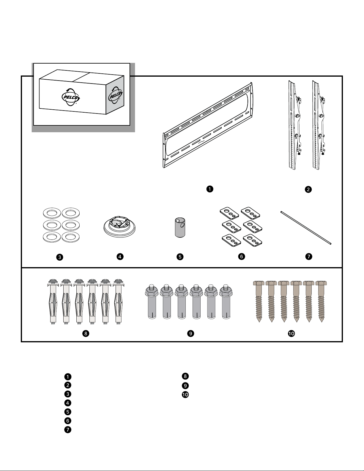
Figure 1. Package Contents
Tilt Wall Mount Parts:
Wall Plate (1 ea.)
Mounting Brackets (2 ea.)
5/16" Flat Washers (6 ea.)
Universal Spacers (24 ea.)
Security Barrel (1 ea.)
Universal Washers (6 ea.)
Thread Depth Indicator (1 ea.)
6 C2258M (5/11)
Pro Mounting Hardware Parts:
M6 Steel Stud Anchors (6 ea.)
5/16" Concrete Wedge Anchors (6 ea.)
5/16" x 3" Lag Bolts (6 ea.)
Page 7
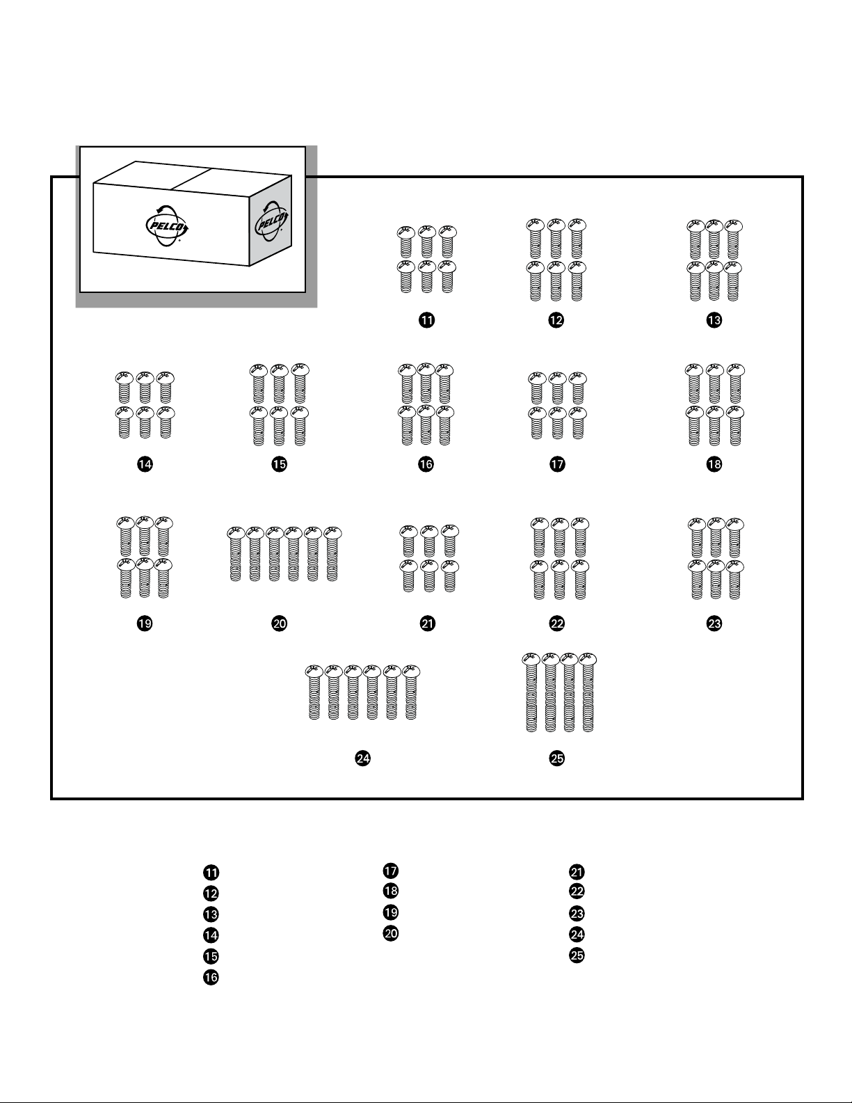
Figure 2. Package Contents Continued
Pan Phillips Screws:
M6 x 16 mm (6 ea.)
M4x 16 mm (6 ea.)
M4 x 25 mm (6 ea.)
M4 x 30 mm (6 ea.)
M5 x 16 mm (6 ea.)
M5 x 25 mm (6 ea.)
M5 x 30 mm (6 ea.)
7 C2258M (5/11)
M6 x 25 mm (6 ea.)
M6 x 30 mm (6 ea.)
M6 x 45 mm (6 ea.)
M8 x 16 mm (6 ea.)
M8 x 25 mm (6 ea.)
M8 x 30 mm (6 ea.)
M8 x 45 mm (6 ea.)
M8 x 70 mm (4 ea.)
Page 8
Installing the Wall Plate
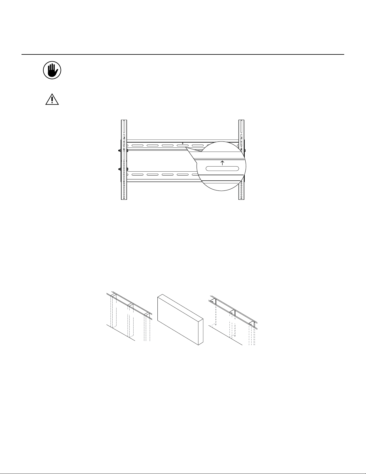
Directional Mounting Arrow
The Directional Mounting Arrow stamped into the top of the PMCLNBWMT wall mount indicates which edge is the top (Figure 3).
Mounting Safety
Two people are recommended for the installation of this mount.
Figure 3. Locating the Directional Mounting Arrow
What are you installing the PMCLNBWMT mount to (Figure 4)?
• If wood studs, proceed to the Wood Stud Installation section on page 9.
• If a concrete wall, proceed to the Concrete Installation section on page 12.
• If a steel frame, proceed to the Steel Stud Installation section on page 15.
Wo
o
d
St
u
d
C
onc
rete
Figure 4. Determining the Mounting Surface
St
e
e
l
St
u
d
8 C2258M (5/11)
Page 9
WOOD STUD INSTALLATION
You must secure the wall plate to two wall studs with a minimum of four lag bolts (two lag bolts for each stud found).
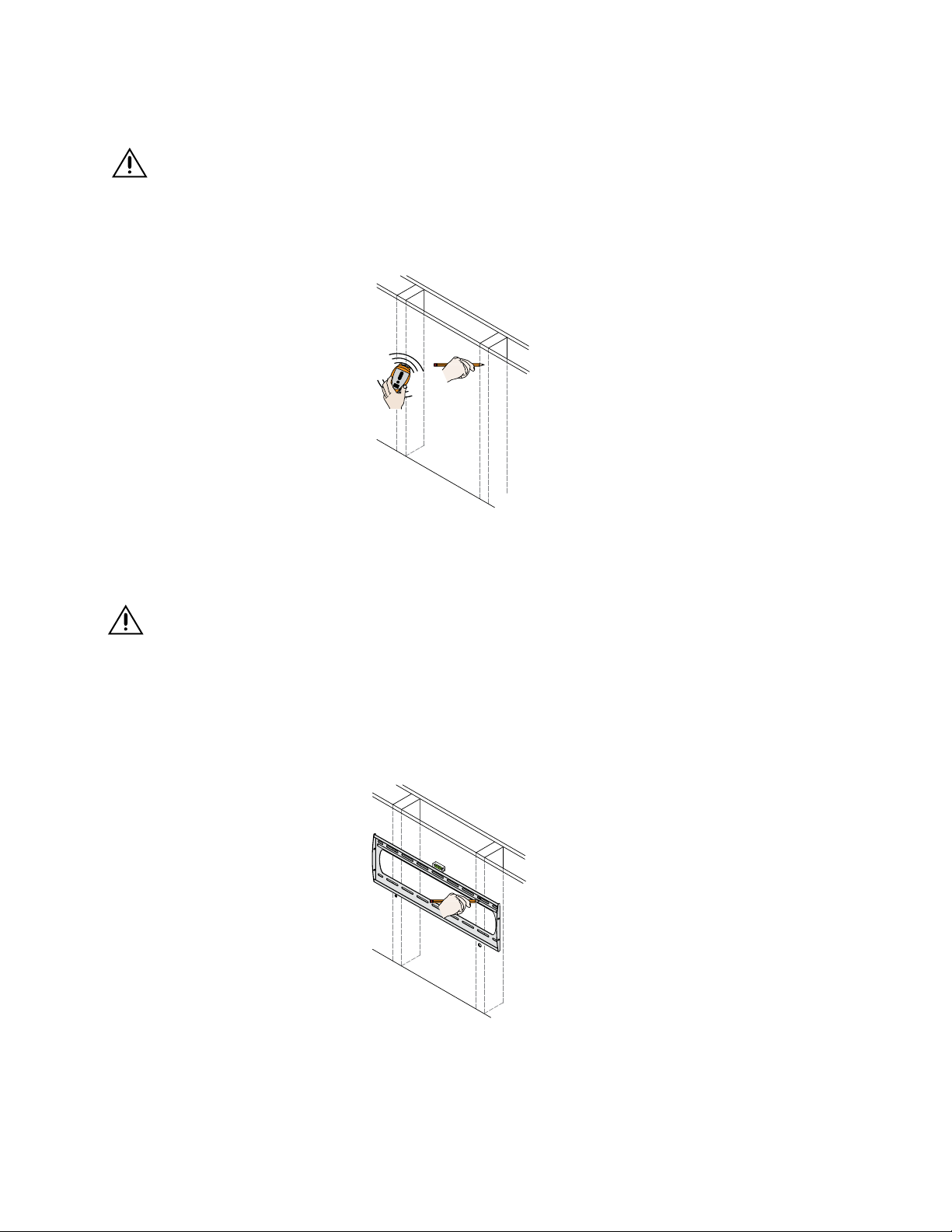
1. Use a stud finder (not included) to determine the exact center of wall studs in the vicinity of the wall plate.
2. Use a pencil (not included) to mark the exact center of each of the wall studs (Figure 5).
X
X
Figure 5. Marking the Center of the Wood Studs
Two people are recommended for this step; one person to level the wall plate and another person to mark the wall stud location.
3. Place the wall plate against the wall in the desired viewing location.
4. Adjust the wall plate to align the mount slots in the wall plate with the center of the wall studs.
5. Level the wall plate.
6. Use a pencil to mark the upper right mounting location along the center of the wall stud (Figure 6).
Figure 6. Marking the Upper Mounting Locations
9 C2258M (5/11)
Page 10

7. Drill a “pilot hole” in the center of the upper right mark using a ¼" drill bit (not included) and power drill (not included) (Figure 7).
Only use a ¼" drill bit when drilling the pilot holes.
Figure 7. Drilling a Pilot Hole
8. Place the wall plate against the wall and align it with the pilot hole.
9. Insert one 5/16" x 3" lag bolt and one 5/16" washer into the upper right mounting hole and tighten using a socket wrench and ½" socket (not included)
(Figure 8).
Do not overtighten the lag bolt.
Figure 8. Inserting a Lag Bolt
10 C2258M (5/11)
Page 11

10. Level the wall plate.
11. Use a pencil (not included) to mark the remaining three mounting locations along the center of each wall stud (Figure 9).
Figure 9. Marking the Remaining Mounting Locations
Two people are recommended for this step; one person to level the wall plate and another person to drill the pilot holes.
12. Drill a “pilot hole” in the center of each of the marks with a power drill and a ¼" drill bit (Figure 10).
Only use a ¼" drill bit when drilling the pilot holes.
Figure 10. Drilling the Remaining Pilot Holes
11 C2258M (5/11)
Page 12

13. Insert one 5/16" x 3" lag bolt and one 5/16" washer into each pilot hole (Figure 11).
14. Tighten all lag bolts using a socket wrench and ½" socket.
Do not overtighten the lag bolts when attaching the mount to the wall. Improper installation may result in personal injury or property damage.
Proceed to the Installing the Mounting Bracket section on page 18.
Figure 11. Inserting the Lag Bolts
CONCRETE INSTALLATION
The supplied 5/16" concrete wedge anchors must be used for concrete installation (Figure 12).
You will need a 5/16" concrete drill bit, which is available at your closest hardware store (Figure 13).
Figure 12. Concrete Wedge Anchors
Figure 13. Example of 5/16" Concrete Drill Bit (not included)
12 C2258M (5/11)
Page 13

Two people are recommended for this step; one person to level the wall plate and another person to mark the mounting locations.
1. Place the wall plate against the wall in the desired viewing location.
2. Level the wall plate.
3. Use a pencil (not included) and mark two upper and two lower mounting locations where you will be drilling holes for the concrete wedge anchors.
Each horizontal location cannot be closer than 12" apart (Figure 14).
4. Set the wall plate to one side in a safe location.
>12”
Figure 14. Placing the Wall Plate
5. Use a power drill (not included) and 5/16" concrete drill (not included) bit to drill a hole at each of the marks (Figure 15).
Figure 15. Drilling a Hole in Concrete
13 C2258M (5/11)
Page 14

6. Insert a concrete wedge anchor into each hole (Figure 16).
If necessary, lightly tap each concrete wedge anchor into place with a hammer.
7. Remove the nuts and washers from all four concrete wedge anchors.
8. Replace the washers which you removed from the concrete wedge anchors with the 5/16" washers shown in the parts list on page 6.
Figure 16. Inserting Concrete Wedge Anchors
9. Place the wall plate against the wall over the threaded shafts of the concrete wedge anchors.
10. Attach the nuts and 5/16" washers to each of the concrete wedge anchors and tighten using a socket wrench and an M10 socket (not included)
(Figure 17).
Do not overtighten the wedge anchor nuts.
Proceed to the Installing the Mounting Bracket section on page 18.
Figure 17. Attaching Nuts and Washers
14 C2258M (5/11)
Page 15

STEEL STUD INSTALLATION
The supplied M6 steel stud anchors must be used to install the mount to steel studs. Do not use lag bolts or wood screws
(Figure 18).
1. Identify the general location on the wall where you will be mounting your flat-panel.
2. Use a stud finder (not included) to determine the exact center of each steel stud in the vicinity of the mounting location (Figure 19).
3. Use a pencil (not included) and mark the exact center of each steel stud.
Steel Stud Anchor Screw Steel Stud Anchor Sleeve
Figure 18. Steel Stud Components
X
Figure 19. Using a Stud Finder
15 C2258M (5/11)
Page 16

4. Place the wall plate against the wall in the desired viewing location.
5. Adjust the wall plate to match the locations of the steel studs.
6. Level the wall plate.
7. Use a pencil (not included) and mark two upper and two lower locations where you will be drilling holes for the steel stud anchors (Figure 20).
8. Set the wall plate to one side in a safe location.
Figure 20. Marking Mounting Holes for Steel Stud Anchors
9. Use a power drill and 7/16" drill bit (not included) to drill a hole at each of the marks (Figure 21).
10. Insert a steel stud anchor into each hole.
If necessary, lightly tap each steel stud anchor into place with a hammer.
Figure 21. Drilling Mounting Holes for Steel Stud Anchors
16 C2258M (5/11)
Page 17

11. Use a Phillips screwdriver to tighten each steel stud anchor screw until the legs have completely compressed against the back of the steel stud.
The steel stud anchor screw will feel tight when you first begin to turn it until the legs begin to compress. The steel stud anchor screw will then
turn easier for several turns. The steel stud anchor screw will again feel tight when the legs have completely compressed against the back of
the drywall. Stop turning the steel stud anchor screw at that point (Figure 22).
Do not overtighten the steel stud anchor screw.
12. Remove the steel stud anchor screws and set them aside.
Steel stud anchors may come with small paper washers. You may leave them on the screw or discard them. These small paper washers do not
replace standard 5/16" washers.
Figure 22. Compressing Steel Stud Anchor Legs
13. Align the wall plate over the steel stud anchor sleeves.
14. Insert a steel stud anchor screw and a 5/16" washer into each steel stud anchor sleeve (Figure 23).
15. Use a Phillips screwdriver and tighten each steel stud anchor screw until it is just snug.
Do not overtighten the steel stud anchor screws.
Do not use a power drill to tighten the steel stud anchor screws.
Proceed to the Installing the Mounting Bracket section on page 18.
X
X
Figure 23. Inserting Steel Stud Anchor Screws
17 C2258M (5/11)
Page 18

Installing the Mounting Bracket
SELECTING THE MOUNTING HARDWARE
1. Insert a small straw or toothpick into the threaded inserts found on the back of the flat-panel.
2. Use a pencil to mark the depth of the threaded insert on the small straw or toothpick.
3. Mark the straw or toothpick 1/8" above the depth of the threaded insert, as shown in Figure 24.
4. Insert the small straw or toothpick into the remaining threaded inserts to compare and verify their depth using the straw or toothpick’s 1/8" allowance
mark.
5. Locate the correct diameter screw for the threaded insert.
If the screw you selected is longer than the 1/8" allowance mark on the small straw or toothpick, as shown in Figure 25 and Figure 26, do not use
this screw. The screw length must not bypass the mark.
6. Test each size of the screws provided.
The correct screws should thread easily into the mounting point and not pull out when tension is applied.
Proceed to the Universal Washer Installation section on page 19.
Marking the 1/8”
Allowance
Small Straw or Toothpick
24
Small Straw
or Toothpick
25
Depth Plus 1/8” Allowance
Mark
Small Straw
or Toothpick
26
Depth Plus 1/8” Allowance
Mark
Figure 24. Marking the Depth Above the Threaded Insert
Figure 25. Finding a Screw with the Correct Length
Figure 26. Finding a Screw with the Incorrect Length
18 C2258M (5/11)
Page 19

UNIVERSAL WASHER INSTALLATION
The Universal Washers and Spacers are designed to accommodate the various M4, M5, M6 and M8 hole sizes required by flat-panels (Figure 27).
Do not place excessive pressure on the back of the flat-panel, as this may damage your flat-panel. The Universal Washer must also be installed
between the head of the mounting screw and the mounting bracket as shown (Figure 28).
Does your flat-panel have recessed mount points, uneven mount points, a curved back or any obstruction near the mount point?
• If Yes, you must install Universal Spacers. Remove the mounting brackets, Universal Washers, and mounting screws from the back of the flat-panel.
Proceed to the Universal Spacer Installation section on page 20.
• If No, skip to the Attaching the Mounting Bracket to the Flat-Panel section on page page 21.
M8
M5, M6
M4
Figure 27. Installing Universal Washers
Mounting Screw
Mounting Screw
Universal Washer
Universal Washer
Mounting Bracket
Mounting Bracket
Flat-Panel
Flat Panel
Universal Spacer
Universal Bracket
Mount Point
Mount Point
Figure 28. Universal Washers and Spacers
19 C2258M (5/11)
Page 20

UNIVERSAL SPACER INSTALLATION
Universal Spacers allow you to attach the mounting bracket to flat-panels which have recessed or uneven mount points. Each Universal Spacer adds ¼" to
the distance between the mounting bracket and your flat-panel.
The Universal Spacers must be stacked and oriented as shown (Figure 29).
The Universal Spacers must only be installed between the mounting bracket and your flat-panel.
The Universal Spacers will fit M4, M5, M6 and M8 screw sizes.
Proceed to the Attaching the Mounting Bracket to the Flat-Panel section on page 21.
1"
¼"
Figure 29. Installing Universal Spacers
20 C2258M (5/11)
Page 21

ATTACHING THE MOUNTING BRACKET TO THE FLAT-PANEL
This section presumes that you have read and understood these sections:
• Selecting the Proper Mounting Hardware
• Universal Washer Installation
• Universal Spacer Installation
1. Place your flat-panel screen-side down on a soft, flat surface.
2. Identify the number and location of the thread inserts on the back of your flat-panel.
3. Align the holes on each mounting bracket with the thread inserts on the back of your flat-panel.
4. Secure each mounting bracket to your flat-panel by inserting a minimum of two screws per bracket (Figure 30).
Do not overtighten the mounting hardware.
Proceed to the Lock-It™ Security Barrel Installation (Optional) section on page 22.
Figure 30. Attaching the Mounting Bracket to the Flat-Panel
21 C2258M (5/11)
Page 22

Lock-It™ Security Barrel Installation (Optional)
Optional security configurations include using commercially available combination or keyed padlocks.
To install the security barrel:
1. Remove the locking screw from the mounting bracket.
2. Place the locking screw into and through the security barrel (Figure 31).
3. Re-insert the locking screw and security barrel into the mounting bracket.
4. Tighten the locking screw and security barrel until seated in the mounting tab (Figure 32).
Do not thread the locking screw any further once it is even with the mounting tab. Threading the locking screw any further will prevent you from
safely attaching the flat-panel to the wall plate.
Do not overtighten the locking screw.
Proceed to the Attaching the Flat-Panel to the Wall Plate section on page 23.
Locking Screw
Figure 31. Placing the Locking Screw Through the Security Barrel
Lock-It™ Security
Barrel
Mounting Tab
Figure 32. Tightening the Security Barrel Against the Mounting Tab
22 C2258M (5/11)
Page 23

Attaching the Flat-Panel to the Wall Plate
This section requires two people.
Do not release your flat-panel until you are certain that top and bottom hooks of both mounting brackets are securely seated on the upper and
lower mounting rails of the wall panel.
1. Raise the flat-panel past the top and bottom mounting rails on the wall panel.
2. Slide the flat-panel down slowly, keeping it close to the wall (Figure 33).
3. Engage the top and bottom mounting brackets to the rails of the wall plate (Figure 34).
Proceed to the Mounting Bracket Adjustments section on page 24.
Figure 33. Sliding the Flat-Panel On the Wall Plate
Figure 34. Using the Mounting Brackets
23 C2258M (5/11)
Page 24

Mounting Bracket Adjustments
LEVELING SCREW ADJUSTMENT
If your flat-panel is tilted too far to one side, the leveling screws will allow you to compensate for this tilt by simply adjusting the screws with a
screwdriver.
1. Loosen both locking screws (Figure 35).
2. Adjust the tilt of your flat-panel.
3. Tighten both locking screws.
It is possible to dislodge your flat-panel while you level your flat-panel. Use extreme caution until you tighten the locking screws.
M6 x 30 mm Leveling Screw
(1 per Bracket)
LOCKING SCREW ADJUSTMENT
After you have finished leveling your flat-panel, be sure to tighten the two M6 x 35 mm locking screws (Figure 36).
Do not overtighten the locking screws.
Figure 35. Adjusting the Leveling Screws
M6 x 35 mm Locking Screw
(1 per Bracket)
Figure 36. Adjusting the Locking Screws
24 C2258M (5/11)
Page 25

Tilt Adjustment
ADJUSTING THE FLAT-PANEL FRICTION TILT ANGLE
1. Place one hand at the center top edge of the flat-panel.
2. Place the other hand on the center bottom edge of the flat-panel.
3. Using the upper hand, gently pull the top of the flat-panel towards you while the lower hand gently pushes the bottom of the flat-panel away from you
(Figure 37).
ADJUSTING THE FLAT-PANEL TO THE ORIGINAL POSITION
1. Place one hand at the center top edge of the flat-panel.
2. Place the other hand on the center bottom edge of the flat-panel.
3. Using the upper hand, gently push the top of the flat-panel towards the wall while the lower hand gently pulls the bottom of the flat-panel away from
the wall (Figure 37).
Figure 37. Adjusting the Tilt
25 C2258M (5/11)
Page 26

Utilizing the Security Barrel
The mount includes one Security Barrel which can provide additional theft deterrence for your flat-panel when used with a padlock or other locking system
(not included).
To use a padlock:
1. Place the locking hook through the hole of the security barrel.
2. Snap the lock and locking hook together (Figure 38).
Figure 38. Using the Security Barrel with a Padlock
Technical Specifications
All measurements are in inches (mm).
26 C2258M (5/11)
Page 27

Warranty
PRODUCT WARRANTY AND RETURN INFORMATION
WARRANTY
Pelco will repair or replace, without charge, any merchandise proved defective in
material or workmanship for a period of one year after the date of shipment.
Exceptions to this warranty are as noted below:
•Fiveyears:
– Fiber optic products
– Unshielded Twisted Pair (UTP) transmission products
– CC3701H-2, CC3701H-2X, CC3751H-2, CC3651H-2X, MC3651H-2, and
MC3651H-2X camera models
•Threeyears:
– Pelco-designed fixed network cameras and network dome cameras
with Sarix™ technology.
– Pelco-branded fixed camera models (CCC1390H Series, C10DN
Series, C10CH Series, and IP3701H Series)
– EH1500 Series enclosures
– Spectra® IV products (including Spectra IV IP)
– Camclosure® Series (IS, ICS, IP) integrated camera systems
– DX Series digital video recorders (except DX9000 Series which is covered
for a period of one year), DVR5100 Series digital video recorders, Digital
Sentry® Series hardware products, DVX Series digital video recorders, and
NVR300 Series network video recorders
– Endura® Series distributed network-based video products
– Genex® Series products (multiplexers, server, and keyboard)
– PMCL200/300/400 Series LCD monitors
– PMCL5xx Series FHD monitors
•Twoyears:
– Standard varifocal, fixed focal, and motorized zoom lenses
– DF5/DF8 Series fixed dome products
– Legacy® Series integrated positioning systems
– Spectra III™, Spectra Mini, Spectra Mini IP, Esprit®, ExSite®, and
PS20 scanners, including when used in continuous motion
applications.
– Esprit Ti and TI2500 Series thermal imaging products
– Esprit and WW5700 Series window wiper (excluding wiper blades).
– CM6700/CM6800/CM9700 Series matrix
– Digital Light Processing (DLP®) displays (except lamp and color wheel). The
lamp and color wheel will be covered for a period of 90
days. The air filter is not covered under warranty.
– Intelli-M® eIDC controllers
•Oneyear:
– Video cassette recorders (VCRs), except video heads. Video heads will
be covered for a period of six months.
•Sixmonths:
– All pan and tilts, scanners, or preset lenses used in continuous motion
applications (preset scan, tour, and auto scan modes).
Pelco will warrant all replacement parts and repairs for 90 days from the date
of Pelco shipment. All goods requiring warranty repair shall be sent freight
prepaid to a Pelco designated location. Repairs made necessary by reason of misuse,
alteration, normal wear, or accident are not covered under this warranty.
Pelco assumes no risk and shall be subject to no liability for damages or loss resulting from
the specific use or application made of the Products. Pelco’s liability for any claim, whether
based on breach of contract, negligence, infringement of any rights of any party or product
liability, relating to the Products shall not exceed the price paid by the Dealer to Pelco for such
Products. In no event will Pelco be liable for any special, incidental, or consequential damages
(including loss of use, loss of profit, and claims of third parties) however caused, whether by the
negligence of Pelco or otherwise.
The above warranty provides the Dealer with specific legal rights. The Dealer may also have
additional rights, which are subject to variation from state to state.
If a warranty repair is required, the Dealer must contact Pelco at (800) 289-9100 or
(559) 292-1981 to obtain a Repair Authorization number (RA), and provide the following
information:
1. Model and serial number
2. Date of shipment, P.O. number, sales order number, or Pelco invoice number
3. Details of the defect or problem
If there is a dispute regarding the warranty of a product that does not fall under
the warranty conditions stated above, please include a written explanation with
the product when returned.
Method of return shipment shall be the same or equal to the method by which the
item was received by Pelco.
RETURNS
To expedite parts returned for repair or credit, please call Pelco at (800) 289-9100 or
(559) 292-1981 to obtain an authorization number (CA number if returned for credit, and RA
number if returned for repair) and designated return location.
All merchandise returned for credit may be subject to a 20 percent restocking and
refurbishing charge.
Goods returned for repair or credit should be clearly identified with the assigned
CA or RA number and freight should be prepaid.
2-10-10
The materials used in the manufacture of this document and its components are compliant to the requirements of Directive 2002/95/EC.
REVISION HISTORY
Manual# Date Comments
C2258M 5/11 Original Version
Pelco, the Pelco logo, Camclosure, Digital Sentry, Endura, Esprit, ExSite, Genex, Intelli-M, Legacy, and Spectra are registered trademarks of Pelco, Inc. © Copyright 2011, Pelco, Inc. All rights reserved.
Spectra III and Sarix are trademarks of Pelco, Inc.
DLP is a registered trademark of Texas Instruments Incorporated.
All product names and services identified throughout this document are trademarks or registered trademarks of their respective companies.
The absence of a trademark or registered trademark from this document does not constitute a waiver of intellectual property rights.
27 C2258M (5/11)
Page 28

www.pelco.com
Pelco by Schneider Electric 3500 Pelco Way Clovis, California 93612-5699 United States
USA & Canada Tel (800) 289-9100 Fax (800) 289-9150
International Tel +1 (559) 292-1981 Fax +1 (559) 348-1120
 Loading...