

PMCL400 Series
TFT LCD Monitor
For use with PMCL400HB Models
C2266M (01/14)

2 C2266M(01/14)

Contents
Important Safety Instructions ........................................................................................................................................................ 4
Important Notices ......................................................................................................................................................................... 6
Regulatory Notices ......................................................................................................................................................... 6
Radio and Television Interference ................................................................................................................................. 6
Legal Notice ................................................................................................................................................................... 6
Video Quality Caution .................................................................................................................................................... 6
Frame Rate Notice Regarding User Selected Options ................................................................................................... 6
Open Source Software ................................................................................................................................................... 7
CCC Power Cord Statement .......................................................................................................................................... 7
ESD Warning ................................................................................................................................................................. 7
Warranty Statement ....................................................................................................................................................... 7
Network Topology Statement ....................................................................................................................................................... 7
Legal Notice (Audio Notice) .......................................................................................................................................................... 7
Description ................................................................................................................................................................................... 8
Models ........................................................................................................................................................................... 8
Recommended Mounts .................................................................................................................................................. 8
Package Contents .......................................................................................................................................................... 9
Installation .................................................................................................................................................................................. 10
Desktop Stand ............................................................................................................................................................. 10
Wall Mounting .............................................................................................................................................................. 10
Rack Mounting ............................................................................................................................................................. 11
Rear Panel Connectors ................................................................................................................................................ 13
Operation ................................................................................................................................................................................... 14
Front Panel Controls .................................................................................................................................................... 14
Remote Control Functions ........................................................................................................................................... 15
On-Screen Display Function ........................................................................................................................................ 16
Automatic Power-Down ....................................................................................................................................................... 16
Video 1, Video 2, S-Video Mode Menu ............................................................................................................................... 17
RGB and DVI Mode Menu .................................................................................................................................................. 19
RGB/DVI Mode Supported Frequencies .................................................................................................................................... 21
Specifications ............................................................................................................................................................................. 22
Pelco Troubleshooting Contact Information ............................................................................................................................... 24
Maintenance ............................................................................................................................................................................... 24
Note for Dimension Drawings ..................................................................................................................................................... 24
C2266M(01/14) 3

Important Safety Instructions
1. Read these instructions.
2. Keep these instructions.
3. Heed all warnings.
4. Follow all instructions.
5. Do not use this apparatus near water.
6. Clean only with dry cloth.
7. Do not block any ventilation openings. Install in accordance with the manufacturer’s instructions.
8. Do not install near any heat sources such as radiators, heat registers, stoves, or other apparatus (including amplifiers)
that produce heat.
9. Do not defeat the safety purpose of the polarized or grounding-type plug. A polarized plug has two blades with one wider
than the other. A grounding plug has two blades and a third grounding prong. The wide blade or the third prong are
provided for your safety. If the provided plug does not fit into your outlet consult an electrician for replacement of the
obsolete outlet.
10. Protect the power cord from being walked on or pinched particularly at plugs, convenience receptacles, and the points
where they exit from the apparatus.
11. Only use attachments/accessories specified by the manufacturer.
12. Use only with the cart, stand, tripod, bracket, or table specified by the manufacturer, or sold with the apparatus. When a
cart is used, use caution when moving the cart/apparatus combination to avoid injury from tip-over.
13. Unplug this apparatus during lightning storms or when unused for long periods of time.
14. Refer all servicing to qualified service personnel. Servicing is required when the apparatus has been damaged in any way,
such as power-supply cord or plug is damaged, liquid has been spilled or objects have fallen into the apparatus, the
apparatus has been exposed to rain or moisture, does not operate normally, or has been dropped.
15. Apparatus shall not be exposed to dripping or splashing and that no objects filled with liquids, such as vases shall be
placed on the apparatus.
16. WARNING: To reduce the risk of fire or electric shock, do not expose this apparatus to rain or moisture.
17. Installation should be done only by qualified personnel and conform to all local codes.
18. Unless the unit is specifically marked as a NEMA Type 3, 3R, 3S, 4, 4X, 6, or 6P enclosure, it is designed for indoor use
only and it must not be installed where exposed to rain and moisture.
19. Use only installation methods and mater ial s capable of suppor ting four ti mes the max imum specif ied loa d.
20. Use stainless steel hardware to fasten the mount to outdoor surfaces.
21. To prevent damage from water leakage when installing a mount outdoors on a roof or wall, apply sealant around the bolt
holes between the mount and mounting surface.
22. An all-pole mains switch with a contact separation of at least 3 mm in each pole shall be incorporated in the electrical
installation of the building.
23. A readily accessible disconnect device shall be incorporated in the building installation wiring.
4 C2266M(01/14)
24. The socket-outlet shall be installed near the equipment and shall be easily accessible.
This symbol indicates that there are important operating and maintenance instructions in the literature
WARNING: This product is sensitive to Electrostatic Discharge (ESD). To avoid ESD damage to this product,
25. A CCC approved power cord must be used to power this equipment when used in China.
CAUTION: These servicing instructions are for use by qualified service personnel only. To reduce the risk of electric shock do
not perform any servicing other that contained in the operating instructions unless you are qualified to do so.
CAUTION: Danger of explosion if battery is incorrectly replaced. Replace only with the same or equivalent type. Dispose of
used batteries according to the instructions provided by the battery manufacturer.
Only use replacement parts recommended by Pelco.
After replacement/repair of this unit’s electrical components, conduct a resistance measurement between the line and exposed
parts to verify the exposed parts have not been connected to the line circuitr y .
The product and/or manual may bear the following marks:
This symbol indicates that dangerous voltage constituting a risk of electric shock is present within this unit.
CAUTION: RISK OF ELECTRIC SHOCK. DO NOT OPEN.
accompanying this unit
WARNING: HAZARDOUS MOVING PARTS. KEEP FINGERS AND OTHER BODY PARTS AWAY.
WARNING: HIGH TOUCH CURRENT. EARTH CONNECTI ON ES S E NTIAL B E FORE CONNECTING
SUPPLY.
Denotes Class II double insulated device.
use ESD safe practices during installation. Before touching, adjusting or handling this product, correctly attach
an ESD wrist strap to your wrist and appropriately discharge your body and tools. For more information about
ESD control and safe handling practices of electronics, please refer to ANSI/ESD S20.20-1999 or contact the
Electrostatic Discharge Association (www.esda.org).
C2266M(01/14) 5

Important Notices
Regulatory Notices
This device complies with Part 15 of the FCC Rules. Operation is subject to the following two conditions: (1) this device may
not cause harmful interference, and (2) this device must accept any interference received, including interference that may
cause undesired operation.
Radio and Television Interference
This equipment has been tested and found to comply with the limits of a Class B digital device, pursuant to Part 15 of the FCC
Rules. These limits are designed to provide reasonable protection against harmful interference in a residential installation. This
equipment generates, uses, and can radiate radio frequency energy and, if not installed and used in accordance with the
instructions, may cause harmful interference to radio communications. However there is no guarantee that the interference will
not occur in a particular installation. If this equipment does cause harmful interference to radio or television reception, which
can be determined by turning the equipment off and on, the user is encouraged to try to correct the interference by one or
more of the following measures:
• Reorient or relocate the receiving antenna.
• Increase the separation between the equipment and the receiver.
• Connect the equipment into an outlet on a circuit different from that to which the receiver is connected.
• Consult the dealer or an experienced radio/TV technician for help.
You may also find helpful the following booklet, prepared by the FCC: “How to Identify and Resolve Radio-TV Interference
Problems.” This booklet is available from the U.S. Government Printing Office, Washington D.C. 20402.
Changes and Modifications not expressly approved by the manufacturer or registrant of this equipment can void your authority
to operate this equipment under Federal Communications Commission’s rules.
This Class B digital apparatus complies with Canadian ICES-003.
Cet appareil numérique de la classe B est conforme à la norme NMB-003 du Canada.
Legal Notice
SOME PELCO EQUIPMENT CONTAINS, AND THE SOFTWARE ENABLES, AUDIO/VISUAL AND RECORDING
CAPABILITIES, THE IMPROPER USE OF WHICH MAY SUBJECT YOU TO CIVIL AND CRIMINAL PENALTIES.
APPLICABLE LAWS REGARDING THE USE OF SUCH CAPABILITIES VARY BETWEEN JURISDICTIONS AND MAY
REQUIRE, AMONG OTHER THINGS, EXPRESS WRITTEN CONSENT FROM RECORDED SUBJECTS. YOU ARE SOLELY
RESPONSIBLE FOR INSURING STRICT COMPLIANCE WITH SUCH LAWS AND FOR STRICT ADHERENCE TO ANY/ALL
RIGHTS OF PRIVACY AND PERSONALTY. USE OF THIS EQUIPMENT AND/OR SOFTWARE FOR ILLEGAL
SURVEILLANCE OR MONITORING SHALL BE DEEMED UNAUTHORI ZED USE IN VIOLATION OF THE END USER
SOFTWARE AGREEMENT AND RESULT IN THE IMMEDIATE TERMINATION OF YOUR LICENSE RIGHTS
THEREUNDER.
Video Quality Caution
Frame Rate Notice Regarding User Selected Options
Pelco systems are capable of providing high quality video for both live viewing and playback. However, the systems can be
used in lower quality modes, which can degrade picture quality, to allow for a slower rate of data transfer and to reduce the
amount of video data stored. The picture quality can be degraded by either lowering the resolution, reducing the picture rate,
or both. A picture degraded by having a reduced resolution may result in an image that is less clear or even indiscernible. A
picture degraded by reducing the picture rate has fewer frames per second, which can result in images that appear to jump or
move more quickly than normal during playback. Lower frame rates may result in a key event not being recorded by the
system.
Judgment as to the suitability of the products for users' purposes is solely the users' responsibility. Users shall determine the
suitability of the products for their own intended application, picture rate and picture quality. In the event users intend to use
6 C2266M(01/14)
the video for evidentiary purposes in a judicial proceeding or otherwise, users should consult with their attorney regarding any
WARNING: This product is sensitive to Electrostatic Discharge (ESD). To avoid ESD damage to this product,
particular requirements for such use.
Open Source Software
This product includes certain open source or other software originated from third parties that is subject to the GNU General
Public License (GPL), GNU Library/Lesser General Public License (LGPL) and different and/or additional copyright licenses,
disclaimers, and notices.
The exact terms of GPL, LGPL, and some other licenses are provided to you with this product. Please refer to the exact terms
of the GPL and LGPL at http://www.fsf.org (Free Software Foundation) or http://www.opensource.org (Open Source Initiative)
regarding your rights under said license. You may obtain a comple te corre spo ndi ng mac hin e-readable copy of the source code
of such software under the GPL or LGPL by sending your request to digitalsupport@pelco.com; the subject line should read
Source Code Request. You will then receive an email with a link for you to download the source code.
This offer is valid for a period of three (3) years from the date of the distribution of this product by Pelco.
CCC Power Cord Statement
Models shipped to China do not include power cords.
NOTE: A CCC approved power cord must be used to power the equipment when used in China.
ESD Warning
use ESD safe practices during installation. Before touching, adjusting or handling this product, correctly attach
an ESD wrist strap to your wrist and appropriately discharge your body and tools. For more information about
ESD control and safe handling practices of electronics, please refer to ANSI/ESD S20.20-1999 or contact the
Electrostatic Discharge Association (www.esda.org).
Warranty Statement
For information about Pelco’s product warranty and thereto related information, refer to www.pelco.com/warranty.
Network Topology Statement
IMPORTANT NOTE. PLEASE READ. The network implementation is shown as a general representation only and is not
intended to show a detailed network topology. Your actual network will differ, requiring changes or perhaps additional network
equipment to accommodate the system as illustrated. Please contact your local Pelco representative to discuss your specific
requirements.
Legal Notice (Audio Notice)
NOTE: Improper use of audio/visual recording equipment may subject you to civil and criminal penalties. Applicable laws
regarding the use of such capabilities vary between jurisdictions and may require, among other things, express written consent
from the recorded subjects. You are solely responsible for insuring strict compliance with such laws and for strict adherence to
any/all right of privacy and personality.
C2266M(01/14) 7

Description
PMCL-WM
LCD flat wall mount for TFT monitors
The PMCL400 Series TFT LCD monitor provides high resolution display of computer signals. These 17-inch and
19-inch monitors use a color, thin film transistor (TFT) active matrix LCD panel (1280 x 1024) that automatically
adapts to the appropriate input resolution. The RGB and DVI mode settings allow the monitor to seamlessly accept a
variety of native resolutions, making the PMCL400 Series compatible with lower resolution products.
The PMCL400 Series features an ergonomic design, autoranging internal power supply, and low power consumption.
These innovations, combined with quick panel response time to minimize ghosting in motion video, make the
PMCL400 Series an ideal choice for use with any digital video recorder (DVR) or PC application.
In addition, the PMCL400 Series features a folding picture frame-style desktop stand, optional rack mount kits, and
®
-compliant mounting holes to easily adapt to the available wall and ceiling mounts.
VESN
The on-screen display (OSD) menus and front panel controls provide easy configuration of standard monitor display
parameters right on the screen. These settings are then stored in the monitor, which eliminates the need for a
computer when adjusting basic monitor functions.
Models
PMCL417HB 17-inch (432 mm) active TFT LCD monitor
PMCL419HB 19-inch (483 mm) active TFT LCD monitor
Recommended Mounts
PMCL-WMT
PMCL-WM1A
PMCL-CM
PMCL-CMP
PMCL-17ARM
PMCL-19ARM
LCD tilt wall mount for TFT monitors
LCD single-arm and dual-arm swing wall mounts for TFT monitors
LCD swivel ceiling mount for TFT monitors
LCD swivel ceiling mount and pole for TFT monitors
LCD rack mount for 17-inch TFT monitors
LCD rack mount for 19-inch TFT monitors
8 C2266M(01/14)

Package Contents
17-inch or 19-inch (Active) TFT LCD Monitor (1 ea.)
USA Standard Power Cord (1 ea.)
European Standard Power Cord (1 ea.)
DVI Cable (1 ea.)
RGB Cable with 15-pin, D-Sub Connector (1 ea.)
Remote Control Unit (1 ea.)
AAA Batteries for Remote Control (2 ea.)
Installation/Operation Manual (1 ea.)
Figure 1. Package Contents
C2266M(01/14) 9
Installation
The monitor can be installed using any of the following options:
•
Desktop Stand
•
Flat Wall Mounting
•
Rack Mounting
Desktop Stand
The monitor comes with a desktop foot stand attached, so it can be placed on any flat surface (desk or table). You
can manually adjust the PMCL400 Series monitor to the viewing angle you want by repositioning the foot stand on
the back of the monitor.
To detach the stand, remove the four mounting screws from the back of the monitor.
Wall Mounting
The monitor can be mounted to a wall using one of the following optional mounts: PMCL-WM, PMCL-WMT, and
PMCL-WM1A wall mount kits if you want the monitor attached to the wall.
•
The PMCL-WM mount has a maximum load capacity of 35 lb (15.9 kg).
•
The PMCL-WMT and PMCL-WM1A mounts have a maximum load capacity of 90 lb (40.8 kg).
WARNING: Pelco strongly recommends that a professional installer performs the bracket and LCD monitor
installation to ensure the proper installation and attach ment
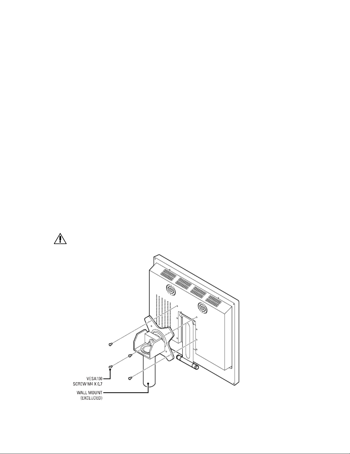
Figure 2. Wall Mount
10 C2266M(01/14)

To mount the monitor to a wall (refer to Figure 2):
1. Align the screw holes in the wall mount with the mounting holes in the back of the monitor.
2. Insert four M4 x 0.7 x 12 mm screws (not supplied), and tighten.
3. Refer to the applicable mount manual for instructions on how to attach the mount to the wall.
Rack Mounting
The monitor can be mounted in a rack using the PMCL-17ARM or PMCL-19ARM rack mount kit (depending on
model). The weight of the mount is 1.1 lb (0.5 kg) and has a max imum load capac ity of 22 lb (10 kg).
To mount the monitor in a rack:
1. Attach the left and right brackets to the monitor using the eight M4 x 0.7 screws (supplied) with the rack mount
kit.
Figure 3. Installing the Brackets
2. Attach the monitor to the rack (refer to Figure 4):
a. Position the monitor brackets against the rack. Align the bracket slots with the holes in the rack.
b. Insert eight screws of an appropriate size (not suppl ied) through the bracket slots and into the holes in
the rack.
c. Tighten the screws.
C2266M(01/14) 11

Figure 4. Installing the Monitor in the Rack
12 C2266M(01/14)

Rear Panel Connectors
Figure 5. Rear Panel Connectors
AC IN: Connects power to the unit from a 100 VAC to 240, 50/60 Hz source.
DVI IN: Provides connection to digital signals from a computer or any Pelco device with DVI output.
RGB IN: Provides connection to RGB output of a computer or any Pelco device with RGB output.
PC AUDIO: Provides audio connection from a PC or recording device. The stereo mini jack is to be used in conjunction
with the RGB input.
S-Video (loop through): Connection of S-Video signals from external sources. The video loops through the four-pin
DIN S-Video output.
Video 1 (loop through): Input connections from DVD players or time-lapse VCRs. The video loops through the BNC
video output.
Video 2 (loop through): Input connections from DVD players or time-lapse VCRs. The video loops through the BNC
video output.
Audio 1 (loop through): Mono RCA audio inputs.
C2266M(01/14) 13

Operation
Front Panel Controls
Figure 6. Front Panel Controls
Menu: Displays the main on-screen menu.
Source: Select the input source and confirms your choic e.
▼ and ▲: Navigation through the on-screen menu
Up button: “Auto” in RGB mode:
VOL(◀ and ▶): Increases or decreases the volume. Also selects or adjusts items in the on-screen menu.
(remote control signal receiver ): Receives remote control signals.
(power button and power indicator): Turns the monitor on and off. Also indicates the power status. Red indicates that
the power is off: green indicates that the power is on.
14 C2266M(01/14)

Remote Control Functions
Figure 7. Remote Control
Power: Turns the monitor on and off.
AUTO: Selects auto adjustment of the screen in the screen of RGB mode.
VOL(◀/VOL- and /VOL+▶, ▼, ▲): Increases or decreases the volume. The up and down arrows let you move the
cursor up and down in the on-screen menu.
ASPECT: Not applicable
ENTER: Confirms (Store or enter) your choice in the on-screen menu.
MENU/EXIT: Displays/exits the on-screen menu.
(input source): Displays all the available input sources. Press the button to select the desired input source.
MUTE: Temporarily silences the sound. To return the sound, press MUTE again.
C2266M(01/14) 15

On-Screen Display Function
The PMCL400 Series on-screen display (OSD) lets you easily change the basic functions of the monitor from the
front panel or the remote control. Figure 8 shows how to change the input source by accessing the menu using the
OSD function. The input source name appears in the upper-right corner of the menu screen any time the input source
is changed or when you press ENTER on the remote control.
Figure 8. Input Source Menu Display
To access the menus:
1. Press the MENU button to access the main menu.
2. Use the up and down arrow buttons (▼, ▲) to highlight a selection.
3. Use the left and right arrow buttons (◀, ▶) to adjust the setting on a selected item.
Automatic Power-Down
This set shall provide a function with the following characteristics as default setting.
1. If there is no input signal(Video, S-Video, RGB, DVI) during 5 minutes, this set shall be automatically switched
from ‘on mode’ to ‘sleep mode’ (stand-by).
2. After going to ‘sleep mode’, there is no wake-up function except RGB mode although signal comes back again.
In order to wake up from ‘sleep mode’ and go back normally, press the power button with proper video input
(Video1, S-Video, DVI)
Note) In RGB mode, monitor goes back to normal mode when video signal comes back again.
16 C2266M(01/14)

Video 1, Video 2, S-Video Mode Menu
Figure 9. Video 1, Video 2 and S-Video Mode Menu
C2266M(01/14) 17

The Video 1, Video 2, S-Video mode menu contains the following features:
Input: Changes the video input option. Select VIDEO or S-VIDEO.
Contrast: Adjusts the black level of the image (0 to 100).
Brightness: Adjust the white level of the image (0 to 100).
Color: Adjusts the color saturation of the video signal (0 to 100).
Sharpness: Adjusts the picture softer or sharper (0 to 100).
Tint: Adjusts the range of color: green to red (0 to 100).
3-D Noise Reduction: Reduces the video signal’s background noise (NORMAL, STRONG, or OFF). NORMAL is the
regular level of noise reduction while STRONG increases the level of noise reduction.
Language: Changes the language selection. Select English, Italian, French, Spanish, German, Portuguese-Brazilian,
Russian, Chinese or Korean for the OSD display.
OSD Setting: Select SETUP for the on-screen display. Then select one of the following.
•
OSD H.POSITION: Adjusts the OSD horizontal position (0 to 100).
•
OSD V.POSITION: Adjusts the OSD vertical position (0 to 100).
•
OSD DISPLAY TIME: Adjusts the display time (OFF or 5 to 30 seconds). Selecting 5 or 30 determines how
many seconds the display remains on the screen when you press a button. Selecting OFF means that there is
no delay.
Color Temperature: Select NORMAL, COOL, or USER. If you select USER, then select from the following:
•
R-Gain: Adjusts gain for red (0 to 100).
•
G-Gain: Adjusts gain for green (0 to 100).
•
B-Gain: Adjusts gain for blue (0 to 100).
•
Reset: Select RESTORE to return to the origina l color tem pe ratur e sett ing s.
ISM: (Image sticking minimization) Sets the recovery time of an LCD panel display when screen burn-in occurs (when
a fixed image has been displayed for a long time.). The operation can be set on the menu. Selects on, off, 1, 2~8
hours.
Default Setting: Select RESTORE to reset the monitor to the default settings.
Information: Select INFORMATION to access Pelco headquarters information.
18 C2266M(01/14)
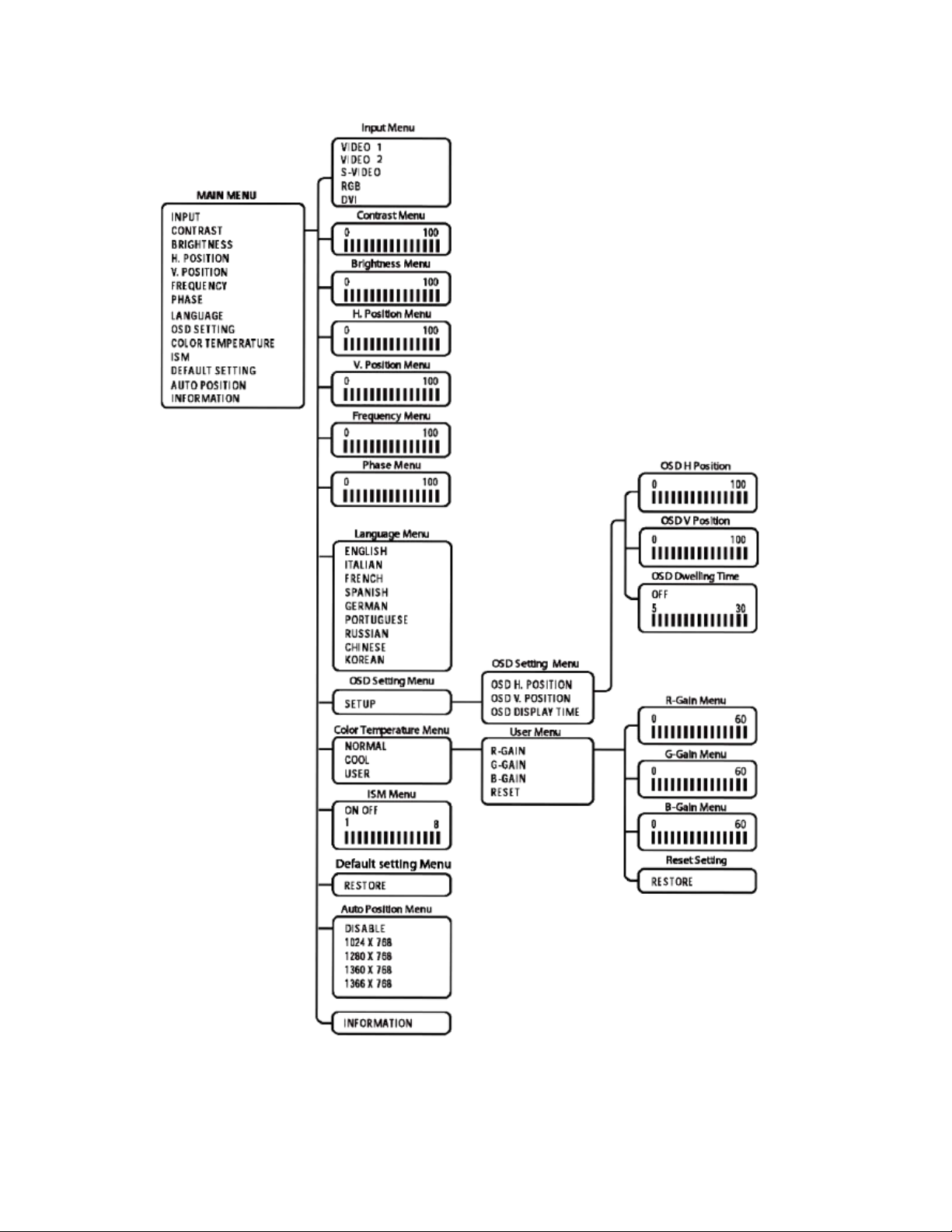
RGB and DVI Mode Menu
Figure 10. RGB and DVI Mode Menu
C2266M(01/14) 19

Not all menus are available for both RGB and DVI. Menus that are unavailable do not appear dimmed, while some
menus that do not apply are not shown.
The RGB and DVI mode menu contains the following features:
Input: Changes the video input option. Select RGB or DVI.
Contrast: Adjusts the black level of the image (0 to 100).
H-Position: (RGB only, dimmed in DVI mode.) Adjusts the horizontal position (0 to 100).
V-Position: (RGB only, dimmed in DVI mode.) Adjusts the vertical position (0 to 100).
Frequency: (RGB only, dimmed in DVI mode.) Adjusts the horizontal size of the screen image (0 to 100)
Phase: (RGB only, dimmed in DVI mode.) Adjust image distortion appearing ad horizontal noise on the screen (0 to
100).
Language: Changes the language selection. Select English, Italian, French, Spanish, German, Portuguese-Brazilian,
Russian, Chinese or Korean for the OSD display.
OSD Setting: Select SETUP for the on-screen display. Then select one of the following.
•
OSD H.POSITION: Adjusts the OSD horizontal position (0 to 100).
•
OSD V.POSITION: Adjusts the OSD vertical position (0 to 100).
•
OSD DISPLAY TIME: Adjusts the display time (OFF or 5 to 30 seconds). Selecting 5 or 30 determines how
many seconds the display remains on the screen when you press a button. Selecting OFF means that there is
no delay.
Color Temperature: Select NORMAL, COOL, or USER. If you select USER, then select from the following:
•
R-Gain: Adjusts gain for red (0 to 100).
•
G-Gain: Adjusts gain for green (0 to 100).
•
B-Gain: Adjusts gain for blue (0 to 100).
•
Reset: Select RESTORE to return to the original color temperature settings.
ISM: (Image sticking minimization) Sets the recovery time of an LCD panel display when screen burn-in occurs (when
a fixed image has been displayed for a long time.). The operation can be set on the menu. S elect s on, off, 1, 2~8
hours.
Default Setting: Select RESTORE to reset the monitor to the default settings.
Auto Position: Changes the display resolution. Select DISABLE, 1024 x 768, 1280 x 768, 1360 x 768, or 1366 x
768.
•
This menu is enabled only when one of the listed resolution settings is selected.
•
If an input signal causes problems on the screen, select a different setting.
•
The Auto Position menu has no effect on resolution inputs that are not listed.
Information: Select INFORMATION to access Pelco headquarters information.
20 C2266M(01/14)

RGB/DVI Mode Supported Frequencies
Table A describes the resolution supported under different frequencies.
NOTE: Not all resolutions generated by your video source are available on the monitor.
Table A. RGB and DVI Mode Supported Frequencies
Mode Resolution Vertical Frequency (Hz)
720X400 70
VGA
640X480 60/72/75
SVGA 800X600 56/60/72/75
XGA 1024X768 60/70/75
SXGA 1280X1024 60/75
WXGA 1280X720 60
C2266M(01/14) 21

Specifications
MODELS
GENERAL
0˚ to 30˚
ELECTRICAL
<42W
ENVIRONMENTAL
PMCL417HB 432 mm (17-inch) active TFT LCD monitor
PMCL419HB 483 mm (19-inch) active TFT LCD monitor
Viewing Area
PMCL417HB 338 x 270 mm
PMCL419HB 376 x 301 mm
Pixel Pitch
PMCL417HB 0.264 x 0.264 mm
PMCL419HB 0.294 x 0.294 mm
Brightness
PMCL417HB 380cd/m2
PMCL419HB 350cd/m2
Contrast Ratio 1000:1
Backlight Type
PMCL417HB 4CCFL
PMCL419HB LED
Viewing Angle (H/V) 170°/160°
Response Time 5 ms
Native Resolution 1280 x 1024 SXGA
Panel Aspect Ratio 5:4
Panel Life 50,000 hours
Tilt
Display Colors 16.7 million
Speakers Integrated, 2 x 2 W
Front Panel Controls Power, source/enter, menu/exit,
up/down, vol +/Indicators LED, power on/off
Power Consumption
PMCL417HB
PMCL419HB <47W
Input Voltage 100 to 240 VAC, 50/60 Hz
Input Interfaces
Video 2 BNC, looping; 1 S-Video, looping; 1 RGB;
1 DVI
Audio 1 (L/R) RCA jack, looping;1 PC
Horizontal Frequency 31 kHz to 80 kHz
Vertical Frequency 56 Hz to 75 Hz
Sync Format NTSC/PAL
Operating Temperature 0° to 40°C (32° to 104°F)
Storage Temperature -20° to 60°C (-4° to 140°F)
Operating Humidity 20% to 80%, noncondensing
Storage Humidity 10% to 90%, noncondensing
250 cd/m2
22 C2266M(01/14)

PHYSICAL
RECOMMENDED MOUNTS
CERTIFICATIONS
Dimensions
PMCL417HB 6.1 x 37.8 x 34.1 cm
(2 4” D x 14.9” W x 13.4” H)
PMCL419HB 6.1 x 41.5 x 36.9 cm
(2 4” D x 16.4” W x 14.5” H)
Unit Weight
PMCL417HB 4.9kg(10.8lb)
PMCL419HB 5.7kg(12.6lb)
Shipping Weight
PMCL417HB 7kg(16lb)
PMCL419HB 8kg(18lb)
Wall Mount PMCL-WM, PMCL-WMT, PMCL-WM1A
Ceiling Mount PMCL -CM, PMCL -CMP
Rack Mount PMCL-17ARM, PMCL-19ARM
Note: The PMCL400 Series are VESA MIS-D, 100/75, C-compliant monitors
equipped with a 100 x 100 mm mounting hole pattern.
- CE, Class B
- FCC, Class B
- UL/cUL Listed
- C-Tick
- CU (PMCL419HB)
- GOST-R(PMCL417HB)
C2266M(01/14) 23

Pelco Troubleshooting Contact Information
WARNING: To reduce the risk of electrical shock, do not remove the cover or back of the monitor. There are no
Problem
Possible Cause
Suggested Resolution
Faulty system or cable
Make adjustments on the front panel control.
Inspect all system connections and cables .
If the instructions provided fail to solve your problem, contact Pelco Product Support at 1-800-289-9100 (USA and Canada) or
+1-559-292-1981 (international) for assistance. Be sure to have the serial number available when calling.
Do not try to repair the unit yourself. Opening it immediately voids the warranty. Leave maintenance and repairs to qualified
technical personnel only.
For information about Pelco's product warranty and thereto related information, refer to www.pelco.com/warranty.
user-serviceable parts inside
Table A. Troubleshooting the PMCL400 Series Monitor
Poor picture quality
connections.
Maintenance
Periodically, you might need to clean the PMCL400 Series LCD monitor to maintain optimum viewing performance. Be sure to
observe the following cleaning instructions to avoid damage to the monitor:
•
Gently wipe your screen with a clean camel-hair brush or a soft, clean, lint-free cloth.
•
Gently apply pressure to the screen surface to clean the display.
•
Do not spray any liquid directly on the screen or the LCD monitor casing. Chemical cleaners can damage the screen
and the LCD monitor casing.
Note for Dimension Drawings
NOTE: VALUES IN PARENTHESES ARE INCHES; ALL OTHERS ARE CENTIMETERS.
24 C2266M(01/14)

C2266M(01/14) 25

26 C2266M(01/14)
 Loading...