

Page 1
INSTALLATION/OPERATION
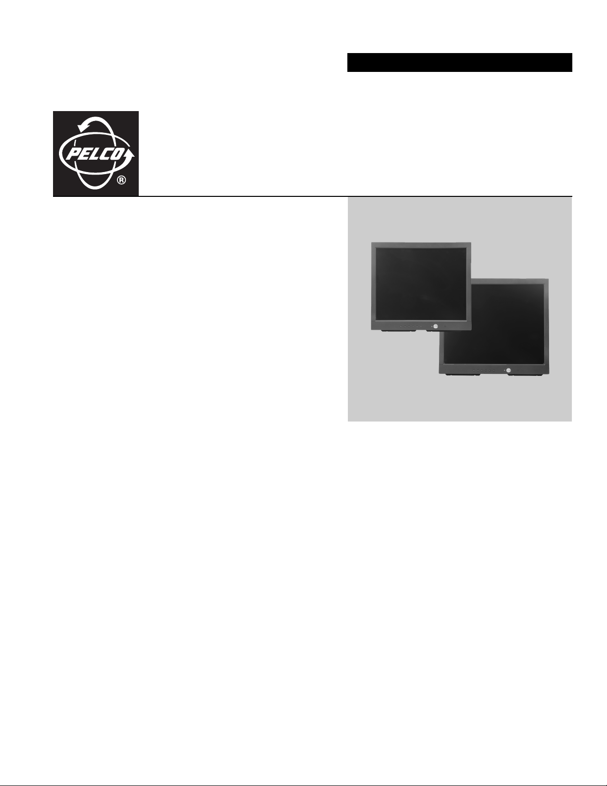
200 Series Flat Panel
LCD Monitors
C2925M-B (12/06)
Page 2

Page 3

Contents
Important Safety Instructions . . . . . . . . . . . . . . . . . . . . . . . . . . . . . . . . . . . . . . . . . . . . . . . . . . . . . . . . . . . . . . . . . . . . . . . . . . . . . . . . . . . . . . . . . . . . 4
Regulatory Notices . . . . . . . . . . . . . . . . . . . . . . . . . . . . . . . . . . . . . . . . . . . . . . . . . . . . . . . . . . . . . . . . . . . . . . . . . . . . . . . . . . . . . . . . . . . . . . . . . . . . 5
Description . . . . . . . . . . . . . . . . . . . . . . . . . . . . . . . . . . . . . . . . . . . . . . . . . . . . . . . . . . . . . . . . . . . . . . . . . . . . . . . . . . . . . . . . . . . . . . . . . . . . . . . . . . 6
Models . . . . . . . . . . . . . . . . . . . . . . . . . . . . . . . . . . . . . . . . . . . . . . . . . . . . . . . . . . . . . . . . . . . . . . . . . . . . . . . . . . . . . . . . . . . . . . . . . . . . . . . . . 6
Package Contents . . . . . . . . . . . . . . . . . . . . . . . . . . . . . . . . . . . . . . . . . . . . . . . . . . . . . . . . . . . . . . . . . . . . . . . . . . . . . . . . . . . . . . . . . . . . . . . . 6
Installation . . . . . . . . . . . . . . . . . . . . . . . . . . . . . . . . . . . . . . . . . . . . . . . . . . . . . . . . . . . . . . . . . . . . . . . . . . . . . . . . . . . . . . . . . . . . . . . . . . . . . . . . . . 7
Desktop Stand . . . . . . . . . . . . . . . . . . . . . . . . . . . . . . . . . . . . . . . . . . . . . . . . . . . . . . . . . . . . . . . . . . . . . . . . . . . . . . . . . . . . . . . . . . . . . . . . . . . 7
Rear Panel Connectors . . . . . . . . . . . . . . . . . . . . . . . . . . . . . . . . . . . . . . . . . . . . . . . . . . . . . . . . . . . . . . . . . . . . . . . . . . . . . . . . . . . . . . . . . . . . . 7
Video and Power Connections . . . . . . . . . . . . . . . . . . . . . . . . . . . . . . . . . . . . . . . . . . . . . . . . . . . . . . . . . . . . . . . . . . . . . . . . . . . . . . . . . . . . . . . 7
Operation . . . . . . . . . . . . . . . . . . . . . . . . . . . . . . . . . . . . . . . . . . . . . . . . . . . . . . . . . . . . . . . . . . . . . . . . . . . . . . . . . . . . . . . . . . . . . . . . . . . . . . . . . . . 8
Front Panel Controls . . . . . . . . . . . . . . . . . . . . . . . . . . . . . . . . . . . . . . . . . . . . . . . . . . . . . . . . . . . . . . . . . . . . . . . . . . . . . . . . . . . . . . . . . . . . . . . 8
OSD Control Menus . . . . . . . . . . . . . . . . . . . . . . . . . . . . . . . . . . . . . . . . . . . . . . . . . . . . . . . . . . . . . . . . . . . . . . . . . . . . . . . . . . . . . . . . . . . . . . . 9
Maintenance . . . . . . . . . . . . . . . . . . . . . . . . . . . . . . . . . . . . . . . . . . . . . . . . . . . . . . . . . . . . . . . . . . . . . . . . . . . . . . . . . . . . . . . . . . . . . . . . . . . . . . . . 12
Cleaning . . . . . . . . . . . . . . . . . . . . . . . . . . . . . . . . . . . . . . . . . . . . . . . . . . . . . . . . . . . . . . . . . . . . . . . . . . . . . . . . . . . . . . . . . . . . . . . . . . . . . . . 12
Main Menu . . . . . . . . . . . . . . . . . . . . . . . . . . . . . . . . . . . . . . . . . . . . . . . . . . . . . . . . . . . . . . . . . . . . . . . . . . . . . . . . . . . . . . . . . . . . . . . . . 9
Display Adjust Menu . . . . . . . . . . . . . . . . . . . . . . . . . . . . . . . . . . . . . . . . . . . . . . . . . . . . . . . . . . . . . . . . . . . . . . . . . . . . . . . . . . . . . . . . 10
Color Temperature Menu . . . . . . . . . . . . . . . . . . . . . . . . . . . . . . . . . . . . . . . . . . . . . . . . . . . . . . . . . . . . . . . . . . . . . . . . . . . . . . . . . . . . . 10
OSD Adjust Menu . . . . . . . . . . . . . . . . . . . . . . . . . . . . . . . . . . . . . . . . . . . . . . . . . . . . . . . . . . . . . . . . . . . . . . . . . . . . . . . . . . . . . . . . . . . 11
Audio Control Menu . . . . . . . . . . . . . . . . . . . . . . . . . . . . . . . . . . . . . . . . . . . . . . . . . . . . . . . . . . . . . . . . . . . . . . . . . . . . . . . . . . . . . . . . . 11
Supported Input Modes . . . . . . . . . . . . . . . . . . . . . . . . . . . . . . . . . . . . . . . . . . . . . . . . . . . . . . . . . . . . . . . . . . . . . . . . . . . . . . . . . . . . . . . . . . . . . . . 13
Specifications . . . . . . . . . . . . . . . . . . . . . . . . . . . . . . . . . . . . . . . . . . . . . . . . . . . . . . . . . . . . . . . . . . . . . . . . . . . . . . . . . . . . . . . . . . . . . . . . . . . . . . . 14
List of Illustrations
1 Rear Panel Connectors . . . . . . . . . . . . . . . . . . . . . . . . . . . . . . . . . . . . . . . . . . . . . . . . . . . . . . . . . . . . . . . . . . . . . . . . . . . . . . . . . . . . . . . . . . . . . 7
2 Front Panel Controls . . . . . . . . . . . . . . . . . . . . . . . . . . . . . . . . . . . . . . . . . . . . . . . . . . . . . . . . . . . . . . . . . . . . . . . . . . . . . . . . . . . . . . . . . . . . . . . 8
3 Main Menu . . . . . . . . . . . . . . . . . . . . . . . . . . . . . . . . . . . . . . . . . . . . . . . . . . . . . . . . . . . . . . . . . . . . . . . . . . . . . . . . . . . . . . . . . . . . . . . . . . . . . . 9
4 Display Adjust Menu . . . . . . . . . . . . . . . . . . . . . . . . . . . . . . . . . . . . . . . . . . . . . . . . . . . . . . . . . . . . . . . . . . . . . . . . . . . . . . . . . . . . . . . . . . . . . 10
5 Color Temperature Menu . . . . . . . . . . . . . . . . . . . . . . . . . . . . . . . . . . . . . . . . . . . . . . . . . . . . . . . . . . . . . . . . . . . . . . . . . . . . . . . . . . . . . . . . . . 10
6 OSD Adjust Menu . . . . . . . . . . . . . . . . . . . . . . . . . . . . . . . . . . . . . . . . . . . . . . . . . . . . . . . . . . . . . . . . . . . . . . . . . . . . . . . . . . . . . . . . . . . . . . . . 11
7 Audio Control Menu . . . . . . . . . . . . . . . . . . . . . . . . . . . . . . . . . . . . . . . . . . . . . . . . . . . . . . . . . . . . . . . . . . . . . . . . . . . . . . . . . . . . . . . . . . . . . . 11
C2925M-B (1/07) 3
Page 4

Important Safety Instructions
1. Read these instructions.
2. Keep these instructions.
3. Heed all warnings.
4. Follow all instructions.
5. Do not use this apparatus near water.
6. Clean only with dry cloth.
7. Do not block any ventilation openings. Install in accordance with the manufacturer’s instructions.
8. Do not install near any heat sources such as radiators, heat registers, stoves, or other apparatus (including amplifiers) that produce heat.
9. Do not defeat the safety purpose of the polarized or grounding-type plug. A polarized plug has two blades with one blade wider than the
other. A grounding plug has two blades and a third grounding prong. The wide blade or the third prong are provided for your safety. If the
provided plug does not fit into your outlet, consult an electrician for replacement of the obsolete outlet.
10. Protect the power cord from being walked on or pinched particularly at plugs, convenience receptacles, and the points where they exit from
the apparatus.
11. Only use attachments/accessories specified by the manufacturer.
12. Use only with the cart, stand, tripod, bracket, or table specified by the manufacturer, or sold with the apparatus. When a cart is used, use
caution when moving the cart/apparatus combination to avoid injury from tip-over.
13. Refer all servicing to qualified service personnel. Servicing is required when the apparatus has been damaged in any way, such as
power-supply cord or plus is damaged, liquid has been spilled or objects have fallen into the apparatus, the apparatus has been exposed to
rain or moisture, does not operate normally, or has been dropped.
14. Apparatus shall not be exposed to dripping or splashing and that no objects filled with liquids, such as vases shall be placed on the
apparatus.
15. WARNING: To reduce the risk of fire or electric shock, do not expose this apparatus to rain or moisture.
16. Installation should be done only by qualified personnel and conform to all local codes.
17. Unless this unit is specifically marked as NEMA Type 3, 3R, 3S, 4, 4X, 6, or 6P enclosure, it is designed for indoor use only and it must not
be installed where exposed to rain and moisture.
18. Use only installation methods and materials capable of supporting four times the maximum specified load.
19. Only use replacement parts recommended by Pelco.
20. Avoid touching the screen directly with your fingers as the oils from your skin may be difficult to remove from the LCD.
21. Do not apply direct pressure on the screen.
22. Keep the monitor in a dust-free environment and away from strong electromagnetic fields.
23. Do not use attachments, such as mounts, that are not recommended by Pelco. They may be hazardous.
24. Do not place the monitor on an unstable stand, bracket, or mount. The unit may fall, causing serious damage to the unit or injury to a
person. Only use mounts recommended by Pelco.
25. A CCC-approved power cord must be used to power this equipment when used in China.
The product and/or manual may bear the following marks:
This symbol indicates that dangerous voltage constituting a risk of electric shock is present
within this unit.
CAUTION:
RISK OF ELECTRIC SHOCK.
This symbol indicates that there are important operating and maintenance instructions in
the literature accompanying this unit
DO NOT OPEN.
4 C2925M-B (1/07)
Page 5

Regulatory Notices
This device complies with Part 15 of the FCC Rules. Operation is subject to the following two conditions: (1) this device may not cause harmful
interference, and (2) this device must accept any interference received, including interference that may cause undesired operation.
RADIO AND TELEVISION INTERFERENCE
This equipment has been tested and found to comply with the limits of a Class B digital device, pursuant to Part 15 of the FCC Rules. These limits
are designed to provide reasonable protection against harmful interference in a residential installation. This equipment generates, uses, and can
radiate radio frequency energy and, if not installed and used in accordance with the instructions, may cause harmful interference to radio
communications. However there is no guarantee that the interference will not occur in a particular installation. If this equipment does cause
harmful interference to radio or television reception, which can be determined by turning the equipment off and on, the user is encouraged to try
to correct the interference by one or more of the following measures:
• Reorient or relocate the receiving antenna.
• Increase the separation between the equipment and the receiver.
• Connect the equipment into an outlet on a circuit different from that to which the receiver is connected.
• Consult the dealer or an experienced radio/TV technician for help.
You may also find helpful the following booklet, prepared by the FCC: “How to Identify and Resolve Radio-TV Interference Problems.” This
booklet is available from the U.S. Government Printing Office, Washington D.C. 20402.
Changes and Modifications not expressly approved by the manufacturer or registrant of this equipment can void your authority to operate this
equipment under Federal Communications Commission’s rules.
This Class B digital apparatus complies with Canadian ICES-003.
Cet appareil numérique de la classe B est conforme à la norme NMB-003 du Canada.
C2925M-B (1/07) 5
Page 6

Description
The 200 Series LCD monitors provide high resolution display of VGA signals. These 17- and 19-inch monitors use a color, thin film transfer (TFT)
active matrix 1280 x 1024 LCD panel that automatically adapts to the appropriate input resolution.
The 200 Series’ ergonomic design, autoranging internal power supply, and low power consumption, combined with quick panel response time to
minimize ghosting in motion video, make the 200 Series an ideal choice for use with any DVR (digital video recorder) or PC application.
In addition, the 200 Series features a folding picture frame-style desktop stand, optional rack mount kits, and VESA®-compliant mounting holes
to easily adapt to the available wall mount.
Adjustments of standard monitor display parameters are made using user-friendly, on-screen menus and front panel controls.
MODELS
PMCL217 17-inch (432 mm) active TFT LCD monitor
PMCL219 19-inch (483 mm) active TFT LCD monitor
PACKAGE CONTENTS
1 17- or 19-inch TFT LCD monitor
1 VGA cable with 15-pin, D-sub connector
1 US standard power cable
1 EU standard power cable
1 Sound cable
1 Installation/Operation manual
TFT LCD MONITOR
SOUND CABLE
6 C2925M-B (1/07)
US STANDARD
POWER CABLE
EU STANDARD
POWER CABLE
INSTALLATION
OPERATION MANUAL
VGA CABLE W/15 PIN
D-SUB CONNECTOR
Page 7

Installation
The monitor can be placed on any flat surface (desk or table), or it can be rack mounted or wall mounted.
NOTE: Only use a recommended rack mount kit, such as PMCL-RM17, PMCL-RM19, or PMCL-WM. To rack-mount the monitor, follow the
instructions supplied with the rack mount kit. Refer to manual C2220M for rack mount kit instructions or C2219M for wall mount kit instructions.
DESKTOP STAND
You can manually adjust the 200 Series monitor to the viewing angle you want by repositioning the foot stand on the back of the monitor.
REAR PANEL CONNECTORS
Figure 1. Rear Panel Connectors
1. AC IN: Can be connected to a 100-240 VAC, 50/60 Hz source.
2. VGA IN: Can be connected to the VGA cable (supplied).
3. AUDIO IN: Can input stereo audio from any sound source.
4. Speakers: The unit has two built-in speakers.
VIDEO AND POWER CONNECTIONS
Refer to Figure 1 for video, audio, and power connections.
1. Connect a PC or DVR to VGA IN on the back panel of the monitor.
2. Connect audio. Connect the audio cable from the stereo output source to the AUDIO IN connection on the back panel.
3. Connect power. Plug the provided power cord into the AC IN connection on the back panel. Plug the other end of the cord into a power
receptacle.
C2925M-B (1/07) 7
Page 8
Operation
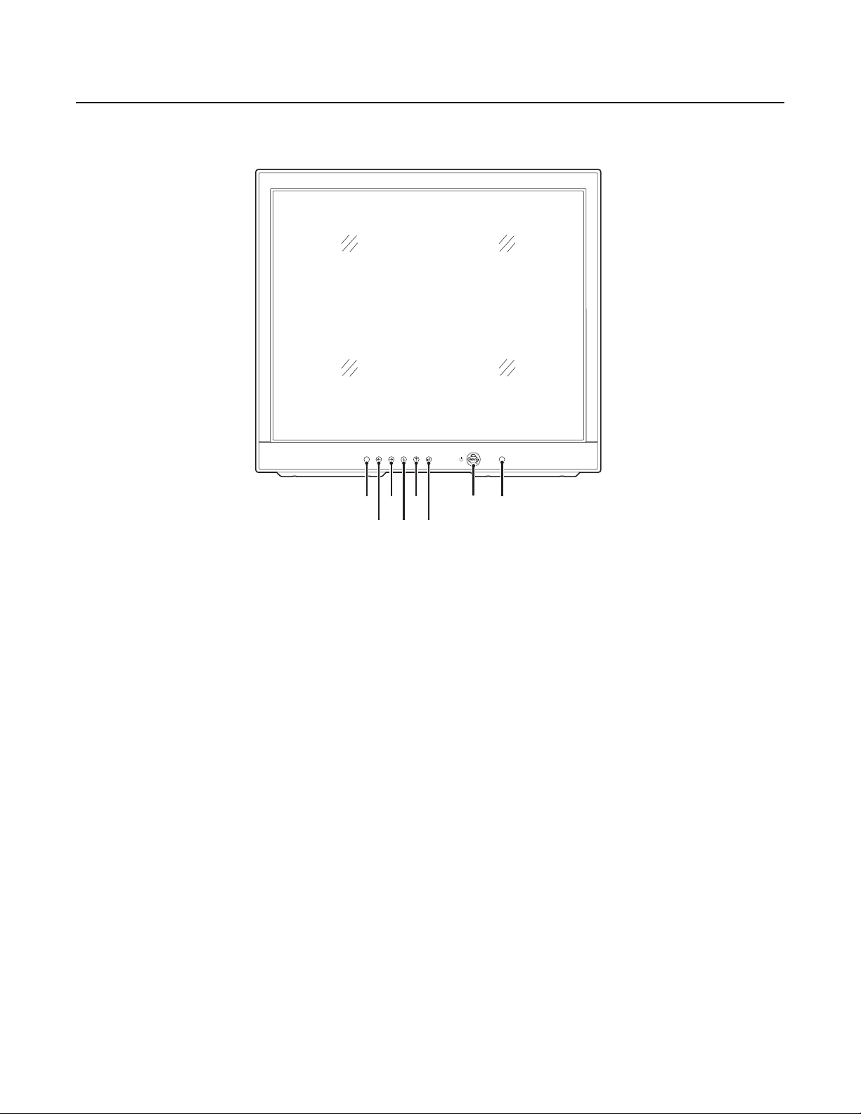
FRONT PANEL CONTROLS
CH
Figure 2. Front Panel Controls
1. Automatically selects the input signal.
2. Decreases the value of a selected menu item or opens the Volume menu and decreases volume.
3. Increases the value of a selected menu item or opens the Volume menu and increases volume.
4. Moves the highlighter downward through a menu.
5. Moves the highlighter upward through a menu.
6. Button accesses the pop-up menu and is also used to select a highlighted menu item.
7. Turns on or off power to the monitor.
8. Receives the remote control system. Infrared sensor (400 Series monitors only).
8 C2925M-B (1/07)
Page 9

OSD CONTROL MENUS
Unless otherwise noted, the menus are the same for the PMCL217 and PMCL219.
To use the menus:
1. Press the menu button to access the Main menu.
2. Use the up and down arrow buttons to highlight a selection.
3. Press the menu button to select an item.
4. Use the left and right arrow buttons to adjust the setting on a selected item.
MAIN MENU
MAIN MENU
VGA IN:
1280x1024
H.SYNC:
-48.3KHz
V.SYNC: -60.8Hz
BRIGHTNESS
CONTRAST
DISPLAY ADJUST
COLOR TEMPERATURE
LANGUAGE
OSD ADJUST
AUDIO CONTROL
RESET
EXIT
LANGUAGE
ENGLISH
SPANISH / ESPAÑOL
GERMAN / DEUTSCH
ITALIAN / ITALIANO
FRENCH / FRANÇAIS
RETURN
Figure 3. Main Menu
The Main menu is accessed by pressing the menu button on the monitor’s front panel. After selecting a highlighted item with the menu button,
use the left and right arrow buttons to adjust the setting.
Main Menu Field Definitions
Brightness: Adjusts the black level of the video screen image.
Contrast: Adjusts the white level of the video screen image.
Display Adjust: Accesses the Display Adjust menu.
Color Temperature: Adjusts the color temperature to 9300K, 7500K, 6500K, or User Preset.
Language: Lets you choose among five languages: English, Spanish, German, Italian, or French.
OSD Adjust: Accesses the OSD (on-screen display) Adjust menu.
Audio Control: Accesses the Audio Control menu.
Reset: Returns all controls to factory settings.
Exit: Exits the menu system.
C2925M-B (1/07) 9
Page 10

DISPLAY ADJUST MENU
DISPLAY ADJUST
V-POSITION
H-POSITION
PITCH
PHASE
SHARPNESS
AUTO TUNING
RECALL
RETURN
Figure 4. Display Adjust Menu
Display Adjust Menu Field Definitions
V-Position: Moves the screen image up or down.
H-Position: Moves the screen image left or right.
Pitch: Adjusts image distortion appearing as vertical bars or noise on the screen.
Phase: Adjusts image distortion appearing as horizontal noise on the screen.
Sharpness: Adjusts the picture softer or sharper.
050
080
050
058
000
Auto Tuning: Adjusts the above settings automatically for the best display.
Recall: Restores this submenu’s settings to the factory defaults.
Return: Takes you back to the Main menu.
COLOR TEMPERATURE MENU
COLOR TEMPERATURE
9300K
7500K
6500K
USER PRESET
RECALL
RETURN
Figure 5. Color Temperature Menu
Color Temperature Menu Field Definitions
9300K, 7500K, 6500K: These settings change the color temperature to suit your preference. Low color temperature implies warmer (more
yellow/red) light while high color temperature implies a colder (more blue) light. The unit of measurement is Kelvin (K).
User Preset: Accesses the User Preset submenu. The options are as follows:
• Red, Green, Blue: These settings let you customize the color temperature to your own preference by adjusting the amount of red, green,
and blue.
• Return: Takes you back to the previous menu.
USER PRESET
RED
GREEN
BLUE
RETURN
050
050
050
Recall: Restores this menu’s settings to the factory default.
Return: Takes you back to the main menu.
10 C2925M-B (1/07)
Page 11

OSD ADJUST MENU
OSD ADJUST
OSD H-POS
OSD V-POS
OSD TIMER
OSD TRANSPARENCY
RECALL
RETURN
Figure 6. OSD Adjust Menu
OSD Adjust Menu Field Definitions
OSD H-Pos: Moves the OSD menu box left or right.
OSD V-Pos: Moves the OSD menu box up or down.
OSD Timer: Sets the number of seconds the menu remains on the screen. The maximum setting is 104.
OSD Transparency: Adjusts the transparency of the OSD menu box.
Recall: Restores this submenu’s settings to the factory defaults.
049
049
020
054
Return: Takes you back to the Main menu.
AUDIO CONTROL MENU
AUDIO CONTROL
MUTE
VOLUME
CALL
RE
RETURN
Figure 7. Audio Control Menu
Audio Control Menu Field Definitions
Mute: Toggles muting on or off. Use the arrow keys to toggle on or off and press the menu button to select.
Volume: Controls the volume. Highlight and use the left or right arrow keys to increase or decrease the volume. Press the menu button to select.
Recall: Restores this submenu’s settings to the factory defaults.
Return: Takes you back to the Main menu.
OFF
050
C2925M-B (1/07) 11
Page 12

Maintenance
If the quality of the picture is poor and cannot be improved by making adjustments on the front control panel, inspect all system connections and
cable runs.
WARNING: To reduce the risk of electrical shock, do not remove the cover or back of the monitor. No user-serviceable parts are inside.
Refer servicing to qualified personnel, or contact the Pelco Customer Service Department for assistance, 1-800-289-9100. Refer to the
Product Warranty and Return Information located on the back inside cover of this manual.
CLEANING
• Gently wipe your screen with a clean camel hair brush or a soft, clean, lint-free cloth.
• Gently apply pressure to the screen surface to clean the display.
• Do not spray any liquid directly on the screen or the LCD monitor casing.
• Chemical cleaners can damage the screen or the LCD monitor casing.
12 C2925M-B (1/07)
Page 13

Supported Input Modes
Mode Resolution H Freq (kHz) V Freq (Hz)
0 720 x 350 31.469 70.087
1 640 x 480 31.469 59.940
2 640 x 480 35.000 66.667
3 640 x 480 37.861 72.809
4 640 x 480 37.500 75.000
5 720 x 400 31.469 70.087
6 800 x 600 35.156 56.250
7 800 x 600 37.879 60.317
8 800 x 600 48.077 72.188
9 800 x 600 46.875 75.000
10 832 x 624 49.750 74.500
11 1024 x 768 48.363 60.004
12 1024 x 768 56.476 70.069
13 1024 x 768 58.038 71.918
14 1024 x 768 60.023 75.029
15 1280 x 1024 64.000 60.000
16 1280 x 1024 80.000 75.000
C2925M-B (1/07) 13
Page 14

Specifications
MODELS
PMCL217 17-inch (432 mm) active TFT LCD monitor
PMCL219 19-inch (483 mm) active TFT LCD monitor
GENERAL
LCD Panel Pixel Array 1280 X 1024, 75 Hz
Panel Aspect Ratio 5:4 VGA
Viewing Area
PMCL217 338 x 270 mm
PMCL219 376 x 301 mm
Pixel Pitch
PMCL217 0.264 x 0.264 mm
PMCL219 0.294 x 0.294 mm
Brightness
PMCL217 300 cd/m
PMCL219 250 cd/m
Contrast Ratio 500:1
Backlight Type 4 CCFL
Panel Lamp Life 40,000 hours
Viewing Angle (H/V)
PMCL217 140°/130°
PMCL219 150°/130°
Tilt <10° to >45°
Display Colors
PMCL217 16.2 million
PMCL219 16.7 million
Response Time 8 ms
Speakers 2, integrated, 1 W each
Front Panel Controls Automatic tuning, menu, access and navigation, power
Indicators LED (power on/off), on-screen (“no signal”)
2
2
ELECTRICAL
Input Voltage 100-240 VAC, 50/60 Hz, internal power supply
Power Consumption <50 W (on), <5 W (standby)
Input Interfaces
Video 1, 15-pin D-sub
Audio 1 (L/R), RCA
Horizontal Frequency 30 kHz to 80 kHz
Vertical Frequency 56 Hz to 75 Hz
PHYSICAL
Dimensions
PMCL217 3.2" D x 15.0" W x 13.4" H (8.0 x 38.1 x 34.1 cm)
PMCL219 3.3" D x 16.6" W x 14.7" H (8.3 x 42.1 x 37.4 cm)
Unit Weight
PMCL217 12.4 lb (5.6 kg)
PMCL219 14.4 lb (6.5 kg)
Shipping Weight
PMCL217 16.0 lb (7.3 kg)
PMCL219 19.0 lb (8.6 kg)
ENVIRONMENTAL
Operating Temperature 32° to 104°F (0° to 40°C)
Storage Temperature -4° to 140°F (-20° to 60°C)
Operating Humidity 20% to 85%, noncondensing
Storage Humidity 5% to 90%, noncondensing
14 C2925M-B (1/07)
Page 15
PRODUCT WARRANTY AND RETURN INFORMATION
WARRANTY
Pelco will repair or replace, without charge, any merchandise proved defective in material or
workmanship for a period of one year after the date of shipment.
Exceptions to this warranty are as noted below:
• Five years on FR/FT/FS Series fiber optic products and TW3000 Series unshielded twisted
pair transmission products.
• Three years on Spectra
• Three years on Genex
• Three years on Camclosure
CC3701H-2X, CC3751H-2, CC3651H-2X, MC3651H-2, and MC3651H-2X camera models,
which have a five-year warranty.
• Three years on PMCL200/300/400 Series LCD monitors.
• Two years on standard motorized or fixed focal length lenses.
• Two years on Legacy
dome products.
• Two years on Spectra III
continuous motion applications.
• Two years on Esprit and WW5700 Series window wiper (excluding wiper blades).
• Two years (except lamp and color wheel) on Digital Light Processing (DLP
The lamp and color wheel will be covered for a period of 90 days. The air filter is not
covered under warranty.
• Eighteen months on DX Series digital video recorders, NVR300 Series network video
recorders, and Endura
• One year (except video heads) on video cassette recorders (VCRs). Video heads will be
covered for a period of six months.
• Six months on all pan and tilts, scanners or preset lenses used in continuous motion
applications (that is, preset scan, tour and auto scan modes).
Pelco will warrant all replacement parts and repairs for 90 days from the date of Pelco
shipment. All goods requiring warranty repair shall be sent freight prepaid to Pelco, Clovis,
California. Repairs made necessary by reason of misuse, alteration, normal wear, or accident
are not covered under this warranty.
Pelco assumes no risk and shall be subject to no liability for damages or loss resulting from
the specific use or application made of the Products. Pelco’s liability for any claim, whether
based on breach of contract, negligence, infringement of any rights of any party or product liability, relating to the Products shall not exceed the price paid by the Dealer to Pelco for such
Products. In no event will Pelco be liable for any special, incidental or consequential damages
(including loss of use, loss of profit and claims of third parties) however caused, whether by
the negligence of Pelco or otherwise.
The above warranty provides the Dealer with specific legal rights. The Dealer may also have
additional rights, which are subject to variation from state to state.
®
IV products.
®
Series products (multiplexers, server, and keyboard).
®
and fixed camera models, except the CC3701H-2,
®
, CM6700/CM6800/CM9700 Series matrix, and DF5/DF8 Series fixed
™
, Esprit®, ExSite™, and PS20 scanners, including when used in
®
) displays.
™
Series distributed network-based video products.
If a warranty repair is required, the Dealer must contact Pelco at (800) 289-9100 or
(559) 292-1981 to obtain a Repair Authorization number (RA), and provide the following
information:
1. Model and serial number
2. Date of shipment, P.O. number, Sales Order number, or Pelco invoice number
3. Details of the defect or problem
If there is a dispute regarding the warranty of a product which does not fall under the
warranty conditions stated above, please include a written explanation with the product when
returned.
Method of return shipment shall be the same or equal to the method by which the item was
received by Pelco.
RETURNS
In order to expedite parts returned to the factory for repair or credit, please call the factory at
(800) 289-9100 or (559) 292-1981 to obtain an authorization number (CA number if returned for
credit, and RA number if returned for repair).
All merchandise returned for credit may be subject to a 20% restocking and refurbishing
charge.
Goods returned for repair or credit should be clearly identified with the assigned CA or RA number and freight should be prepaid. Ship to the appropriate address below.
If you are located within the continental U.S., Alaska, Hawaii or Puerto Rico, send goods to:
Service Department
Pelco
3500 Pelco Way
Clovis, CA 93612-5699
If you are located outside the continental U.S., Alaska, Hawaii or Puerto Rico and are instructed
to return goods to the USA, you may do one of the following:
If the goods are to be sent by a COURIER SERVICE, send the goods to:
Pelco
3500 Pelco Way
Clovis, CA 93612-5699 USA
If the goods are to be sent by a FREIGHT FORWARDER, send the goods to:
Pelco c/o Expeditors
473 Eccles Avenue
South San Francisco, CA 94080 USA
Phone: 650-737-1700
Fax: 650-737-0933
The materials used in the manufacture of this document and its components are compliant to the requirements of Directive 2002/95/EC.
This equipment contains electrical or electronic components that must be recycled properly to comply with Directive 2002/96/EC of the European Union
regarding the disposal of waste electrical and electronic equipment (WEEE). Contact your local dealer for procedures for recycling this equipment.
REVISION HISTORY
Manual # Date Comments
C2925M 12/05 Original version.
C2925M-A 1/06 For the PMCL217, changed diagonal screen size to 432 mm. For the PMCL219, changed unit depth to 3.3 inches (8.3 cm).
C2925M-B 12/06 Changed all response times from 12 ms to 8 ms.
Pelco, the Pelco logo, Camclosure, Esprit, Genex, Legacy, and Spectra are registered trademarks of Pelco. © Copyright 2006, Pelco. All rights reserved.
Endura and ExSite are trademarks of Pelco.
DLP is a registered trademark of Texas Instruments, Inc.
VESA is a registered trademark of the Video Electronics Standards A ssociation.
Page 16

Australia
|
Canada
|
Finland
|
France
Worldwide Headquarters
3500 Pelco Way
Clovis, California 93612 USA
USA & Canada
Tel: 800/289-9100
Fax: 800/289-9150
International
Tel: 1-559/292-1981
Fax: 1-559/348-1120
www.pelco.com
ISO9001
|
Italy
|
Russia
|
Singapore
|
Spain
|
Sweden
|
The Netherlands
|
United Arab Emirates
|
United Kingdom
|
United States
 Loading...