

Page 1

NET5500 Series
VIDEO ENCODER
Quick Start Guide
English
NET5501
NET5504
NET5508
NET5516
C5653M-A (10/14)
Page 2

IMPORTANT SAFETY INSTRUCTIONS
1.
Read these instructions.
2.
Keep these instructions.
3.
Heed all warnings.
4.
Follow all instructions.
5.
Do not use this apparatus near water.
6.
Clean only with dry cloth.
7.
Do not block any ventilation openings. Insta ll in accordance with the manufacturer’s instructions.
8.
Do not install near any heat sources such as radiators, heat registers, stoves, or other apparatus (including
amplifiers) that produce heat.
9.
Do not defe at the safety purpose of the polarized or grounding-t ype plug. A polarized plug has two blades with
one wider than the other. A grounding plug has two blades and a third grounding prong. The w ide blade or the
third prong are provided for your safet y. If the provided plug does not fit into your outlet consult an electrician for
replacement of the obsolete outlet.
10.
Protect the power cord from being walked on or pinched par ticularly at plugs, convenience receptacles, and the
points where they exit from the apparatus.
11.
Only use attachments/accessories specified by the manufacturer.
12.
Use only with the ca rt, stand, tripod, bracket, or table specified by the manufacturer, or
sold with the apparatus. When a car t is used, use caution when moving the cart/apparatus
combination to avoid injur y from tip-over.
13.
Unplug this apparatus during lightning storms or when unused for long periods of time.
14.
Refer all servicing to qualified ser vice personnel. Ser vicing is required when the apparatus has
been damaged in any way, such as power-supply cord or plug is damaged, liquid has been
spilled or objects have fallen into the apparatus, the apparatus has been expose d to rain or moisture, does not
operate normally, or has been dropped.
15.
Apparatus shall not be exposed to dripping or splashing and that no obje cts filled with liquids, such as vases shall
be placed on the apparatus.
16.
WARNING : To reduce the risk of fire or electric shock, do not expose this apparatus to rain or moisture.
17.
Installation should be done only by qualified personnel and conform to all local codes.
18.
Unless the unit is specifically marked as a NEMA Type 3, 3R, 3S, 4, 4X, 6, or 6P enclosure, it is designed for indoor
use only and it must not be installed where exposed to rain and moisture.
19.
Use only installation methods and materials capable of supporting four times the ma ximum specified load.
20.
A readily accessible disconnect device shall be incorporated in the building installation wiring.
21.
The socket-outlet shall be installed near the equipment and shall be easily accessible.
22.
A CCC approved power c ord must be used to power this equipment when used in China.
CAUTION
|
2
English
This symbol indicates that there are important operating and maintenance instructions in the literature
accompanying this unit.
WARNING : This produ ct is sensitive to El ectros tatic Discharg e (ESD). To avoid ESD da mage to this
product, use ESD safe practices during installation. Before touching, adjusting or handling this product,
correctly attach an ESD w rist str ap to your wr ist and a ppropr iately d ischarge your bo dy and too ls. For more
inform ation ab out ESD control and safe handling practice s of electronics, pleas e refer to ANSI/ESD S20. 201999 or contact the Electrostatic Discharge Association (www.esda.org).
Page 3

IMPORTANT NOTICES
REGULATORY NOTICES
This device complies w ith Par t 15 of the FCC Rules. Operation is subject to the following two c onditions: (1) this devi ce may not
cause harmful interference, and (2) this device mu st acce pt any interfere nce received, including inter ference that may c ause
undesired operation.
RADIO AND TELEVISION INTERFERENCE
This eq uipment has been tested and found to comply with the lim its of a Cla ss A digital devi ce, purs uant to Par t 15 of the FCC
rules. These limits are designed to provi de reasonable protection against harm ful interfere nce whe n the equipment is operated in
a commercial environment. This equipm ent generates, uses, and c an radiate radio frequency energ y and, if not installed and used
in accordance w ith the instruction manual, may cause harmful inte rference to radio communications. Operation of this equipment
in a residential area is li kely to cau se harmful interference in which case the user w ill be req uired to correct the inter ference at his
own expe nse.
Changes and Modific ations not expres sly app roved by the m anufacturer or registrant of thi s equipment can void your authori ty to
operate this equipment under Federal Communications Commission’s rules.
CAN ICES-3(A)/NMB-3(A)
LEGAL NOTICE [Audio Notice]
SOME PELCO EQUIPMEN T CONTAINS, AND THE SOF TWAR E ENABLES, AUDIO/ VISUAL AND RECORDING CAPABILITIES,
THE IMPROPER USE OF W HICH MAY SUBJECT YOU TO CIVIL A ND CRIMI NAL PENA LTIES. APPLICABLE LAWS R EGARDING
THE USE OF SUCH CAPABIL ITIES VARY BE TWEEN JURISD ICTIONS AND MAY REQUIRE, AMONG OTHER THINGS, EXPRESS
WRIT TEN CONS ENT FROM RECORDED SUBJECTS. YOU ARE SOL ELY RESPONSIB LE FOR INSURING STRICT COMPLIANCE
WITH SUC H LAWS AND FOR STRICT ADHERENCE TO ANY/ALL RIGHTS OF PRIVACY AND PERSONALTY. USE OF TH IS
EQUIPMENT AND/OR SOFTWARE FOR ILL EGAL SURVEILL ANCE OR M ONITORING SHALL BE DEEMED U NAUTHO RIZED
USE IN VIO LATION OF T HE END USER S OFT WARE AGREEMENT AND R ESULT IN THE IMM EDIATE TERMINATION OF YOUR
LICENSE RIGHTS THEREUNDER.
VIDEO QUALIT Y CAUTION
FRAME RATE NOTICE REGARDING USER SELECTED OPTIONS
Pelco systems are c apabl e of provid ing high qualit y video for both li ve viewing and playback. H owever, the systems can be used
in lower qualit y modes, w hich ca n degrade pictu re quality, to allow for a slower ra te of data tra nsfer and to reduc e the amou nt
of video data store d. The picture quality c an be deg raded by e ither lowering the resolution, reducin g the picture rate, or b oth.
A picture degraded by havi ng a reduc ed reso lution m ay resul t in an image that is less clear or even indisce rnibl e. A picture
degraded by reducing the picture rate has fewer frames per second, which can result in i mages that appe ar to jump or move
more qui ckly than normal during playback. Lower frame rates may res ult in a key event not being recorded by the system.
Judgment as to the suitability of the products for users' purposes is solely the users' responsibility. Users shall determine the
suitability of the products for th eir own intended a pplic ation, pi cture rate and picture quality. In the event user s intend to use
the video for evidentiary purposes in a judici al proceeding or other wise, us ers sho uld consult with their at torney regarding any
particular require ments for such use.
OPEN SOURCE SOFTWARE
This pro duct includes certain open source or other sof tware originated from third par ties th at is subj ect to the GNU General
Public L icens e (GPL), GNU Librar y/Less er Gene ral Public License (LGPL) and dif ferent and/or additional copyr ight licenses,
disclaimers, and notices.
The exac t terms of GPL, LGPL, and some other licens es are provided to yo u with this product. Please refer to the ex act terms
of the GPL an d LGPL at http://www.fsf.org (Free Soft ware Foundation) or http://ww w.openso urce.org (Open Source Initiative)
regard ing your r ights under said licens e. You may obtain a c omplete corresponding machi ne-readable c opy of the so urce cod e of
such sof tware under th e GPL or LGPL by sending your requ est to digitalsu ppor t@pelc o.com; the subject line shou ld read So urce
Code Request. You wil l then receive an e mail wi th a link for you to downl oad the source cod e.
This of fer is valid for a period of three (3) year s from the date of the distribu tion of thi s produc t by Pelco.
English | 3
Page 4

CCC POWER CORD STATEMENT
Models shipped to China d o not include power cords.
Note : A CCC approved power cord m ust be used to power th e equipment when used in China.
Korean Class A EMC
이 기기는 업무용 (A급) 전자파 적합기기로서 판매자 또는 사용자는 이 점을 주의하시길 바라며, 가정 외의 지역에서 사용하는
것을 목적으로 합니다.
This is a Class A pro duct. In a domestic environment th is produ ct may cau se radio i nterference in which c ase the user may be
required to take adequate me asures.
ESD WARNING
WARNING: This product is sensitive to Electrostatic Discharge (ESD). To avoid ESD damage to this
product, use ESD safe practices during installation. Before touching, adjusting or handling this product,
correctly attach an ESD w rist str ap to your wr ist and a ppropr iately d ischarge your bo dy and too ls. For more
inform ation ab out ESD control and safe handling practice s of electronics, pleas e refer to ANSI/ESD S20. 201999 or contact the Electrostatic Discharge Association (www.esda.org).
Warranty
For infor mation about Pelco’s product warran ty and th ereto rel ated information, refer to www.pelco.com/warranty.
NETWORK TOPOLOGY STATEMENT
IMPOR TANT NOTE. PLEASE R EAD. The n etwork implementati on is show n as a gene ral represent ation only and is not intended
to show a detailed network to pology. Your actual net work will differ, requiri ng changes or pe rhaps additional network equ ipment
to accommodate the system as illustrated. Plea se contact your local Pelco repre sentative to discuss your specif ic requiremen ts.
LEGAL NOTICE (AUDIO NOTICE)
Improp er use of au dio/vi sual recordin g equipment may subject you to civil a nd crim inal pe naltie s. Applicable laws regarding th e use of such
J
capab ilitie s vary between jurisd iction s and may re quire, among othe r things, express written consent from th e recorded subj ects. You are
solely responsible for insuring strict compliance with such laws and for strict adherence to any/all right of privacy and personalty.
|
4
English
Page 5

INTRODUCTION
The NET5500 Series vi deo enc oder is a n etwork-based channel e ncode r with a bui lt-in, Web-based viewer for l ive streaming to a
standard Web browser (Mic rosof t® Internet Exp lorer ®, Chrome®, Safari® or Mozilla® Firefox®). The encoder is built upon o pen
standards and is part of a n Endura® system for record ing, managing, ad ministering, and viewi ng vide o stream s.
The enc oder su pports H.264 and MJPEG com pression. It can generate two independ ently co nfigu rable H. 264 strea ms, each up
to D1 resolution (720 x 480 for NTSC, 720 x 576 for PAL) and 30/25 imag es per se cond (ips) in addi tion to an MJPEG stream for
Web view ing.
The NET5500 ca n be configured for one alarm inpu t for each video channel. When an a larm eve nt is triggered, the unit can send
a messa ge to an ope rator, and trigger a relay.
The uni t also supports motion detection for each v ideo ch annel. You ca n confi gure one m otion zon e, each wi th its own independent
sensitivity and thre shold setting s. When th e NET550 0 detects activity in any of these ar eas, it can trigg er an ala rm event.
The video encoder supports one audio input for each video channel over the network. The system operator (security personnel)
can see a nd hear a ctivity in any ta rget are a in whic h a microp hone is present.
The NET5500 supports control of remote pe riphe rals such as pan/tilt/zoom (PT Z) cameras by way of D -Protocol, P-Protoc ol, and
Coaxitron® protocols.
Models
~NET5501 One-channel H. 264 rack e ncoder
~NET5504 Four-channel H.264 rack encoder
~NET550 8 Eight-channel H.264 rack encoder
~NET5516 Sixte en-channel H. 264 rack e ncode r
Getting Started
Before installing your device, thoroughly familiarize yourself with the information in the installation section of this manual.
NOTES
~Pelco recommends connecting the device to a network that uses a Dynamic Host Configuration Protocol (DHCP) server
to addres s devices.
~Do not use a n etwork hub when configuring the netwo rk settings for the devic e.
~To ensure sec ure access, place the dev ice beh ind a firewall whe n it is con nected to a n etwork.
SUPPLIED PARTS LIST
NET5501
Instal lation M anual, S afety In struction (2ea) / Re source Disc (1ea) / Adapter (1ea) / Rubbe r Feet (4ea) / R ack Mount Ear (2ea) /
Cable Clamp (1ea) / Screw (2ea) for Cable Clam p binding 1 plus 1 sp are / Screw (3ea) for R ack Mount Bracket / Screw (4ea) for
Product Rack bin ding / 5-Pin Terminal Block (2ea)
NET5504
Instal lation M anual, S afety In struction (2ea) / Re source Disc (1ea) / Adapter (1ea) / Rubbe r Feet (4ea) / R ack Mount Ear (2ea) /
Cable Clamp (1ea) / Screw (2ea) for Cable Clam p binding 1 plus 1 sp are / Screw (3ea) for R ack Mount Bracket / Screw (4ea) for
Product Rack bin ding / 6- Pin Termina l Block (2ea)
NET5508
Instal lation M anual, S afety In struction (2ea) / Re source Disc (1ea) / Adapter (1ea) / Rubbe r Feet (4ea) / R ack Mount Ear (2ea) /
Cable Clamp (1ea) / Screw (2ea) for Cable Clam p binding 1 plus 1 sp are / Screw (3ea) for R ack Mount Bracket / Screw (4ea) for
Product Rack bin ding / 10-Pin Terminal B lock (2ea) / D ust Filter (1ea)
NE T5 516
Instal lation M anual, S afety In struction (2ea) / Re source Disc (1ea) / Adapter (1ea) / Rubbe r Feet (4ea) / R ack Mount Ear (2ea) /
Cable Clamp (1ea) / Screw (2ea) for Cable Clam p binding 1 plus 1 sp are / Screw (3ea) for R ack Mount Bracket / Screw (4ea) for
Product Rack bin ding / 8-Pin Terminal Block (2ea) / 10-Pin Termin al Bloc k (2ea) / Dust Filter (1ea)
English | 5
Page 6

FRONT PANEL DESCRIPTION
NET5501/NET5504
NET5508/NET5516
No. Name Description
a
Front Panel Indicators
NET5500 Series
Video Encoder
a
NET5500 Series
Video Encoder
a
Displays power O n/Off status.
It glows blue when the unit has power.
Displays network status (connection and speed).
Off : The unit is not connected to the network.
Solid amber : The unit is connected to the network using the 100 Mbps
standard.
Solid red : The unit is connected to the network using the 10 Mbps standard.
Solid green : The unit is connected to the network using the 1 Gbps standard.
A blinking ligh t indicates network acti vity c orrespondin g to the speed
based on the color.
Displays camera connection status.
Not Lit : A camera has not bee n conne cted yet.
Green : Camera vi deo is present at the video in conne ctor.
Red : Video is no longe r present, the cam era is not f unctio ning properly.
Displays unit status.
Green : The unit is functioning normally.
Red : The unit i s in an error condition.
|
6
English
Page 7

REAR PANEL DESCRIPTION
NET5501
a b e fc d g
NET5504
A NO COM Tx+ Rx+
1
NC Tx- Rx-
1
A1 A2 NO COM Tx+ Rx+
A3 A4 NC Tx- Rx-
a b efc d g
NET5508
Tx+ Tx- NO1 COM1 NC1 A1 A2 A3 A4
Rx+ Rx- NO2 COM2 NC2 A5 A6 A7 A8
1 3
2 4
a b c d e
NE T5 516
Tx+Tx- NO1 COM1 NC1 A1 A2 A3 A4
Rx+ Rx- NO2 COM2 NC2 A5 A6 A7 A8
NO3 COM3 NC3 A9 A10 A11 A12
NO4 COM4 NC4 A13 A14 A15 A16
1 3
2 4
a b c d e
5 7
6 8
5 7
6 8
9 11
10 12
1 2
1 2
13 15
14 16
3 4
3 4
1 2
1 2
1 3
2 4
1 3
2 4
3 4
5 6
3 4
5 6
f g
5 7
9 11
6 8
10 12
g
7 8
7 8
13 15
14 16
English | 7
Page 8

No. Name Description
1
1
A NO COM Tx+ Rx+
NC Tx- Rx-
1
1
A NO COM Tx+ Rx+
A NO COM Tx+ Rx+
NC Tx- Rx-
1
1
1
1
A NO COM Tx+ Rx+
NC Tx- Rx-
a
b
c
d
e
f
g
A Alarm input sensor terminal
NO/NC Relay control
COM Relay common
TX+/TX- RS-422 and RS-485 Data lines
RX+/RX-
Power input socket. For connection of 12V adapter.
Press this switch to reset dev ice to the fa ctory d efault.
If you per form th e factor y reset, a ll your settings to d evice will be los t.
RS-422 RX Data line
Disab led in RS-485 mod e.
J
Ground terminal.
LAN connection to a router or internal network.
Video E ncode r. Audio input terminal for sou nd input.
A microphone or other source of sound may be connected to this.
Video o utput BNC terminal.
Video input BNC terminal.
PTZ, Relay and Alarm Pin Assignments
Label Lead Label Lead
A1 Alarm 1 A3 Alarm 3
A2 Alarm 2 A4 Alarm 4
NO Relay Normally Open
COM Relay Common NC Relay Normally Closed
TX+ RS-422 Dat a TX+ TX- RS- 422 Data T X-
RX+ RS-422 Data RX+ RX- RS-422 Data RX-
|
8
English
Ground
Page 9
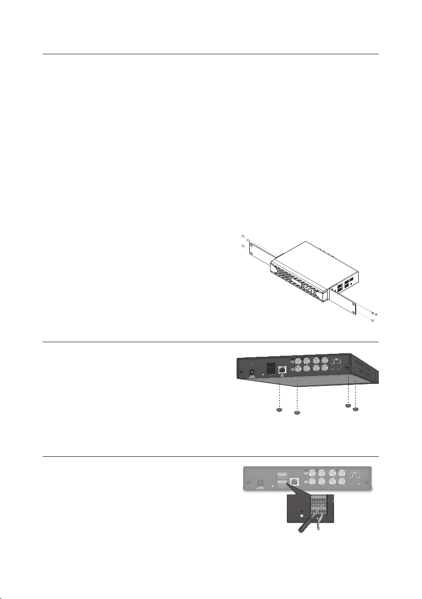
MOUNTING IN A RACK
1 2
1 2
3 4
3 4
2 4
1 3
A1 A2 NO COM Tx+ Rx+
A3 A4 NC Tx- Rx-
1
1
A1 A2 NO COM Tx+ Rx+
A3 A4 NC Tx- Rx-
The NET5500 Series en coder m ounts into an indus try-standard 4 8 cm (19-inch) equipme nt rack. T he NET5500 Ser ies enc oder
occupies 1 RU (4.45 cm or 1.75 inches) of vertica l rack space. The hardware n ecessary to mount the NET5500 S eries encoder
into a rack is suppli ed with the unit.
The rack must meet the following requirements
Rack sta ndard : 48 cm (19 inches), EIA-310-D compliant (rea r column required)
Rack column depth : 50.8 to 76.2 cm (20 to 30 i nches)
Column mounting hole provisions : 10-32 UNF-2B threaded holes or square window holes on front and rear columns
Door sys tems (optional) : Fro nt doors must have at least 5.1 cm (2 inch es) between the NET5500 S eries encoder front bezel and the
inside of the door.
Rear do ors may be u sed onl y on rack columns that more th an 66 cm (26 in ches) de ep.
Make sure the NET5500 Series enc oder is level.
J
Slots and openings in the cabinet p rovide ventilation to preve nt the uni t from overheating. Do not bl ock these openings.
J
To install the NET5500 Series encoder in a rack
Remove th e three Ph illips f lat head screws from each s ide of the unit. Set the screws aside.
1.
Align the three screw holes in the mounting brackets with the
2.
threaded hole s on the lef t and the right si des of the c hassis.
Using the six Phil lips flat head sc rews, attach the mounting
3.
brackets to each side of the cha ssis.
Inser t and tighten the Phi llips flat head screws you re moved earlier.
4.
Align the two mou nting bracket hol es on eac h side with the scre w
5.
holes on the rack.
Inser t and tig hten the Phillips f lat head screws (not suppli ed) to
6.
secure the unit in the rack.
DESKTOP INSTALLATION
When installi ng the dev ice on a horizontal surf ace such as a desk top,
proceed as follows.
Attach the rubber feet to the bottom of th e unit to prevent sur face
1.
damage.
Place the device in a location that provides a dequate space for
2.
wiring and cord s at the front and back of the panel.
Do not pla ce the dev ice upr ight since that can lead to its fallin g over and
J
becom ing damaged. Pla cing the d evice upright will also block th e flow
of air, which may cause it to overhe at.
CONNECTING THE TERMINAL BLOCK
The terminal bl ock has te nsion clamps in stead of sc rew terminals. Us e a
small screwdri ver to open the clam p for a par ticular lead.
A1 A2 NO COM Tx+ Rx+
A3 A4 NC Tx- Rx-
4
3
3
1
2
1
2
1
4
2
4
3
English | 9
Page 10
ACCESSING THE ENCODER AND ATTACHED CAMERAS
The fir st time you access the camera, the li ve video page appears. B y defaul t, you are vi ewing the video a s a public user and o nly
have access to the si ngle stream live v iew.
If, for security purposes, user s should not be allowed to view v ideo wi thout first log ging on to th e camera, change the per missi ons
for public users.
Logging In
Entering the IP add ress of th e camer a as a URL into the web browser will immediately br ing up the Live Mod e screen if the
encoder is not setup to require authentication (Open Authentication option).
If the cam era is setup to require authe ntication, then the user will be prompted for a Username and Pas sword before bein g able
to see the li ve video feed.
Click <Login> on the live scre en.
1.
Enter your <Username> and <Password>.
2.
Defaul t usern ame : admin, Passwo rd : admin
Click th e <Login> button.
3.
The Ope n Authenticati on option is configured on the Settings > Use rs > General Set tings screen.
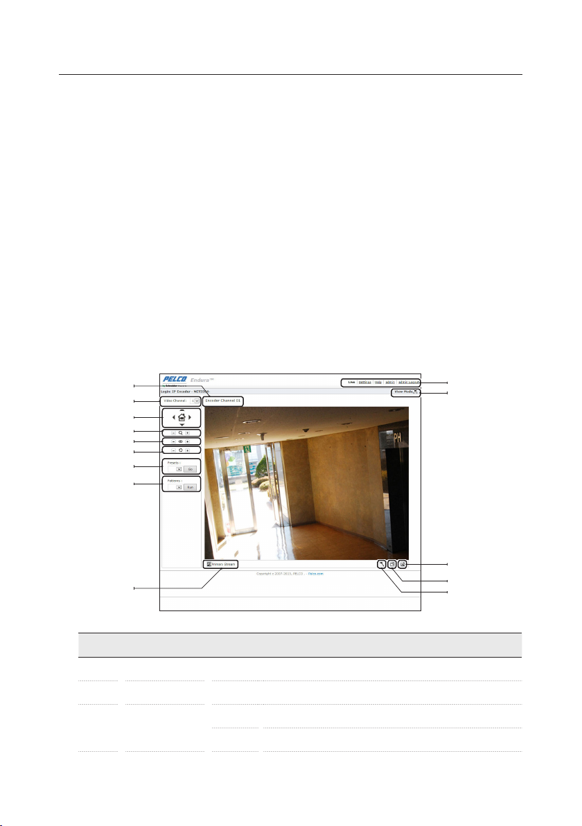
Live Screen Over view
Live Mode Screen Components
a
b
c
d
e
f
g
h
i
No. Name Description
Channel Name Displays the name assigned to the channel selected.
Video Channel Choose number 1 to number of channels on the encoder.
Multi-Function Image
Button
10
a
b
c
|
English
j
k
l
m
n
$
%
Tilt Up
Tilt Down
Page 11

No. Name Description
c
d
e
f
g
h
i
j
k
l
m
n
+
Multi-Function Image
Button
Control the Zoom Activates Zoom i n (-) / Zoom out (+) featu res.
Control the Focus Activates Nea r (-) / Far (+) features.
Control the Iris Adjusts the camera brightness.
Move to Pres ets Moves to the preset sele cted.
Pattern Activate s the pattern selected.
Stream Selection
View the Selected Tab Composed of Live, Settin gs, Help, and Logou t settings menu s.
Maximize Viewing Are a
Take a Snapshot Capture s the image displ ayed in the v ideo pa ne and saves it as a JPEG file.
Open Stream in
New Window
Pan/Tilt/Zoom
_
Selec ts the viewable vi deo stre am that di splays i n live view (Prima ry, Secondary, QuickView) and
selects unicast or multicast and throttle settings.
Scale s the imag e to the full size of the browser. To resize the v ideo pa ne to normal view, click the Show
Toolbar button in the upper-right corner of the window.
Opens the video in a scalable, ind epend ent window. Openi ng the vid eo in a sep arate window allows
you to view the video while oth er applications are running. This window can be mi nimize d, maxi mized,
or closed using the title bar buttons of the active wind ow. The wind ow can also be resized by drag ging
a corne r of the window.
Control the enco der and the pan (left/right) and tilt (up/down) of the connected ca mera by dr agging the
mouse. Also, zoom using the scroll wheel on the mouse.
Pan Righ t
Pan Left
Home Preset
It will not be prese nted to use rs who are designated as Viewers.
These i cons are always available when using the Pel co Medi a Player. If you are using
QuickTime®, PTZ overlay is only available with PMP player.
This equipment contains electrical or electronic components that must be recycled properly to comply with Directive 2012/19/EU
of the European Union regarding the disposal of waste electrical and electronic equipment (WEEE). Contact your local dealer for
procedures for recycling this equipment.
REVISION HISTORY
Manua l # Date Comments
C5653M
C5653M-A
Pelco, the Pelco logo, and other trademarks associated with Pelco products referred to in this publication are trademarks
of Pelco, Inc. or its affiliates.
ONVIF and the ONVIF logo are trademarks of ONVIF Inc. All other product names and services are the property of their
respective companies.
Product specification and availability are subject to change without notice.
07/14
10/14
Original version
Changed power consumption values.
Changed the mod el name (Network Video Encoders ; Video Encoder)
© Copyright 2014, Pelco. Inc.
All rights reserved.
English | 11
Page 12

Pelco by Schneider Elec tric 350 0 Pelco Way C lovis, California 93612-5699 United States
USA & Cana da Tel (800) 289 -9100 Fax (80 0) 289-9150
International Tel +1 (559) 292-1981 Fax +1 (559) 348-1120
www.pelco.com www.pelco.com/community
 Loading...