

Page 1

INSTALLATION
Endura® NET5308T-EXP Eight-Input Dual-Stream Video Encoder
For Use with NET5300B Multichannel
Video Encoder Base Module
C2655M-A (10/08)
Page 2

Page 3

Contents
Regulatory Notices . . . . . . . . . . . . . . . . . . . . . . . . . . . . . . . . . . . . . . . . . . . . . . . . . . . . . . . . . . . . . . . . . . . . . . . . . . . . . . . . . . . . . . . . . . . . . . . . . . . . 5
Video Quality Caution . . . . . . . . . . . . . . . . . . . . . . . . . . . . . . . . . . . . . . . . . . . . . . . . . . . . . . . . . . . . . . . . . . . . . . . . . . . . . . . . . . . . . . . . . . . . . . . . . . 5
Frame Rate Notice Regarding User-Selected Options . . . . . . . . . . . . . . . . . . . . . . . . . . . . . . . . . . . . . . . . . . . . . . . . . . . . . . . . . . . . . . . . . . . . 5
Description . . . . . . . . . . . . . . . . . . . . . . . . . . . . . . . . . . . . . . . . . . . . . . . . . . . . . . . . . . . . . . . . . . . . . . . . . . . . . . . . . . . . . . . . . . . . . . . . . . . . . . . . . . 6
Before You Begin . . . . . . . . . . . . . . . . . . . . . . . . . . . . . . . . . . . . . . . . . . . . . . . . . . . . . . . . . . . . . . . . . . . . . . . . . . . . . . . . . . . . . . . . . . . . . . . . . . . . . 7
Parts List . . . . . . . . . . . . . . . . . . . . . . . . . . . . . . . . . . . . . . . . . . . . . . . . . . . . . . . . . . . . . . . . . . . . . . . . . . . . . . . . . . . . . . . . . . . . . . . . . . . . . . . 7
Package Contents . . . . . . . . . . . . . . . . . . . . . . . . . . . . . . . . . . . . . . . . . . . . . . . . . . . . . . . . . . . . . . . . . . . . . . . . . . . . . . . . . . . . . . . . . . . . . . . . 8
Application Scenario . . . . . . . . . . . . . . . . . . . . . . . . . . . . . . . . . . . . . . . . . . . . . . . . . . . . . . . . . . . . . . . . . . . . . . . . . . . . . . . . . . . . . . . . . . . . . . 9
Product Serial Number Placement . . . . . . . . . . . . . . . . . . . . . . . . . . . . . . . . . . . . . . . . . . . . . . . . . . . . . . . . . . . . . . . . . . . . . . . . . . . . . . . . . . . . . . . 11
Rack Mounting . . . . . . . . . . . . . . . . . . . . . . . . . . . . . . . . . . . . . . . . . . . . . . . . . . . . . . . . . . . . . . . . . . . . . . . . . . . . . . . . . . . . . . . . . . . . . . . . . . . . . . 12
Connections . . . . . . . . . . . . . . . . . . . . . . . . . . . . . . . . . . . . . . . . . . . . . . . . . . . . . . . . . . . . . . . . . . . . . . . . . . . . . . . . . . . . . . . . . . . . . . . . . . . . . . . . 16
Connecting to the NET5300B . . . . . . . . . . . . . . . . . . . . . . . . . . . . . . . . . . . . . . . . . . . . . . . . . . . . . . . . . . . . . . . . . . . . . . . . . . . . . . . . . . . . . . . 16
Connecting Video Input and Output Devices . . . . . . . . . . . . . . . . . . . . . . . . . . . . . . . . . . . . . . . . . . . . . . . . . . . . . . . . . . . . . . . . . . . . . . . . . . . 17
Connecting Audio . . . . . . . . . . . . . . . . . . . . . . . . . . . . . . . . . . . . . . . . . . . . . . . . . . . . . . . . . . . . . . . . . . . . . . . . . . . . . . . . . . . . . . . . . . . . . . . . 19
Connecting Relay Devices . . . . . . . . . . . . . . . . . . . . . . . . . . . . . . . . . . . . . . . . . . . . . . . . . . . . . . . . . . . . . . . . . . . . . . . . . . . . . . . . . . . . . . . . . 20
Connecting Alarms . . . . . . . . . . . . . . . . . . . . . . . . . . . . . . . . . . . . . . . . . . . . . . . . . . . . . . . . . . . . . . . . . . . . . . . . . . . . . . . . . . . . . . . . . . . . . . . 21
Connecting Power . . . . . . . . . . . . . . . . . . . . . . . . . . . . . . . . . . . . . . . . . . . . . . . . . . . . . . . . . . . . . . . . . . . . . . . . . . . . . . . . . . . . . . . . . . . . . . . 24
Connecting Sequence Monitor . . . . . . . . . . . . . . . . . . . . . . . . . . . . . . . . . . . . . . . . . . . . . . . . . . . . . . . . . . . . . . . . . . . . . . . . . . . . . . . . . . . . . 24
Connecting Video Input . . . . . . . . . . . . . . . . . . . . . . . . . . . . . . . . . . . . . . . . . . . . . . . . . . . . . . . . . . . . . . . . . . . . . . . . . . . . . . . . . . . . . . . 18
Camera Control: Coaxitron . . . . . . . . . . . . . . . . . . . . . . . . . . . . . . . . . . . . . . . . . . . . . . . . . . . . . . . . . . . . . . . . . . . . . . . . . . . . . . . . . . . . 18
Camera Control: Pelco D/Pelco P Protocol . . . . . . . . . . . . . . . . . . . . . . . . . . . . . . . . . . . . . . . . . . . . . . . . . . . . . . . . . . . . . . . . . . . . . . . . 18
Connecting Looping Video . . . . . . . . . . . . . . . . . . . . . . . . . . . . . . . . . . . . . . . . . . . . . . . . . . . . . . . . . . . . . . . . . . . . . . . . . . . . . . . . . . . . 19
Supervised Alarms . . . . . . . . . . . . . . . . . . . . . . . . . . . . . . . . . . . . . . . . . . . . . . . . . . . . . . . . . . . . . . . . . . . . . . . . . . . . . . . . . . . . . . . . . . 21
Unsupervised Alarms . . . . . . . . . . . . . . . . . . . . . . . . . . . . . . . . . . . . . . . . . . . . . . . . . . . . . . . . . . . . . . . . . . . . . . . . . . . . . . . . . . . . . . . . 22
Alarm Connections . . . . . . . . . . . . . . . . . . . . . . . . . . . . . . . . . . . . . . . . . . . . . . . . . . . . . . . . . . . . . . . . . . . . . . . . . . . . . . . . . . . . . . . . . . 22
Operation . . . . . . . . . . . . . . . . . . . . . . . . . . . . . . . . . . . . . . . . . . . . . . . . . . . . . . . . . . . . . . . . . . . . . . . . . . . . . . . . . . . . . . . . . . . . . . . . . . . . . . . . . . 25
Front Panel Controls and Indicators . . . . . . . . . . . . . . . . . . . . . . . . . . . . . . . . . . . . . . . . . . . . . . . . . . . . . . . . . . . . . . . . . . . . . . . . . . . . . . . . . . 25
Unit Startup . . . . . . . . . . . . . . . . . . . . . . . . . . . . . . . . . . . . . . . . . . . . . . . . . . . . . . . . . . . . . . . . . . . . . . . . . . . . . . . . . . . . . . . . . . . . . . . . . . . . 26
Unit Shutdown . . . . . . . . . . . . . . . . . . . . . . . . . . . . . . . . . . . . . . . . . . . . . . . . . . . . . . . . . . . . . . . . . . . . . . . . . . . . . . . . . . . . . . . . . . . . . . . . . . 26
Troubleshooting . . . . . . . . . . . . . . . . . . . . . . . . . . . . . . . . . . . . . . . . . . . . . . . . . . . . . . . . . . . . . . . . . . . . . . . . . . . . . . . . . . . . . . . . . . . . . . . . . . . . . 27
Specifications . . . . . . . . . . . . . . . . . . . . . . . . . . . . . . . . . . . . . . . . . . . . . . . . . . . . . . . . . . . . . . . . . . . . . . . . . . . . . . . . . . . . . . . . . . . . . . . . . . . . . . . 28
C2655M-A (10/08) 3
Page 4

List of Illustrations
1 Major Package Components . . . . . . . . . . . . . . . . . . . . . . . . . . . . . . . . . . . . . . . . . . . . . . . . . . . . . . . . . . . . . . . . . . . . . . . . . . . . . . . . . . . . . . . . . 8
2 Accessory Pack . . . . . . . . . . . . . . . . . . . . . . . . . . . . . . . . . . . . . . . . . . . . . . . . . . . . . . . . . . . . . . . . . . . . . . . . . . . . . . . . . . . . . . . . . . . . . . . . . . . 8
3 Rack Mount Kit . . . . . . . . . . . . . . . . . . . . . . . . . . . . . . . . . . . . . . . . . . . . . . . . . . . . . . . . . . . . . . . . . . . . . . . . . . . . . . . . . . . . . . . . . . . . . . . . . . . 9
4 Security Network with One NET5300B and Two NET5308T-EXPs. . . . . . . . . . . . . . . . . . . . . . . . . . . . . . . . . . . . . . . . . . . . . . . . . . . . . . . . . . . 10
5 Product Serial Number Label . . . . . . . . . . . . . . . . . . . . . . . . . . . . . . . . . . . . . . . . . . . . . . . . . . . . . . . . . . . . . . . . . . . . . . . . . . . . . . . . . . . . . . . 11
6 Attaching Chassis Mounting Brackets . . . . . . . . . . . . . . . . . . . . . . . . . . . . . . . . . . . . . . . . . . . . . . . . . . . . . . . . . . . . . . . . . . . . . . . . . . . . . . . . 12
7 Assembling a Support Rail . . . . . . . . . . . . . . . . . . . . . . . . . . . . . . . . . . . . . . . . . . . . . . . . . . . . . . . . . . . . . . . . . . . . . . . . . . . . . . . . . . . . . . . . . 13
8 Inserting Cage Nuts . . . . . . . . . . . . . . . . . . . . . . . . . . . . . . . . . . . . . . . . . . . . . . . . . . . . . . . . . . . . . . . . . . . . . . . . . . . . . . . . . . . . . . . . . . . . . . 13
9 Attaching Support Rails . . . . . . . . . . . . . . . . . . . . . . . . . . . . . . . . . . . . . . . . . . . . . . . . . . . . . . . . . . . . . . . . . . . . . . . . . . . . . . . . . . . . . . . . . . . 14
10 Mounting the NET5308T-EXP into the Rack . . . . . . . . . . . . . . . . . . . . . . . . . . . . . . . . . . . . . . . . . . . . . . . . . . . . . . . . . . . . . . . . . . . . . . . . . . . . 14
11 Tightening the Thumbscrews . . . . . . . . . . . . . . . . . . . . . . . . . . . . . . . . . . . . . . . . . . . . . . . . . . . . . . . . . . . . . . . . . . . . . . . . . . . . . . . . . . . . . . . 15
12 NET5308T-EXP Rear Panel . . . . . . . . . . . . . . . . . . . . . . . . . . . . . . . . . . . . . . . . . . . . . . . . . . . . . . . . . . . . . . . . . . . . . . . . . . . . . . . . . . . . . . . . . 16
13 Connecting an NET5308T-EXP to a NET5300B . . . . . . . . . . . . . . . . . . . . . . . . . . . . . . . . . . . . . . . . . . . . . . . . . . . . . . . . . . . . . . . . . . . . . . . . . . 17
14 Video Inputs and Outputs . . . . . . . . . . . . . . . . . . . . . . . . . . . . . . . . . . . . . . . . . . . . . . . . . . . . . . . . . . . . . . . . . . . . . . . . . . . . . . . . . . . . . . . . . . 17
15 NET5308T-EXP Audio Connections. . . . . . . . . . . . . . . . . . . . . . . . . . . . . . . . . . . . . . . . . . . . . . . . . . . . . . . . . . . . . . . . . . . . . . . . . . . . . . . . . . . 19
16 Relay Control Terminal Block . . . . . . . . . . . . . . . . . . . . . . . . . . . . . . . . . . . . . . . . . . . . . . . . . . . . . . . . . . . . . . . . . . . . . . . . . . . . . . . . . . . . . . . 20
17 Connecting a Relay Device . . . . . . . . . . . . . . . . . . . . . . . . . . . . . . . . . . . . . . . . . . . . . . . . . . . . . . . . . . . . . . . . . . . . . . . . . . . . . . . . . . . . . . . . . 21
18 Supervised Alarm Conditions . . . . . . . . . . . . . . . . . . . . . . . . . . . . . . . . . . . . . . . . . . . . . . . . . . . . . . . . . . . . . . . . . . . . . . . . . . . . . . . . . . . . . . . 21
19 Supervised Alarm Input Wiring . . . . . . . . . . . . . . . . . . . . . . . . . . . . . . . . . . . . . . . . . . . . . . . . . . . . . . . . . . . . . . . . . . . . . . . . . . . . . . . . . . . . . 22
20 Unsupervised Alarm Conditions . . . . . . . . . . . . . . . . . . . . . . . . . . . . . . . . . . . . . . . . . . . . . . . . . . . . . . . . . . . . . . . . . . . . . . . . . . . . . . . . . . . . . 22
21 Unsupervised Alarm Input Wiring . . . . . . . . . . . . . . . . . . . . . . . . . . . . . . . . . . . . . . . . . . . . . . . . . . . . . . . . . . . . . . . . . . . . . . . . . . . . . . . . . . . 22
22 Alarm Terminal Block . . . . . . . . . . . . . . . . . . . . . . . . . . . . . . . . . . . . . . . . . . . . . . . . . . . . . . . . . . . . . . . . . . . . . . . . . . . . . . . . . . . . . . . . . . . . . 23
23 Connecting Alarms . . . . . . . . . . . . . . . . . . . . . . . . . . . . . . . . . . . . . . . . . . . . . . . . . . . . . . . . . . . . . . . . . . . . . . . . . . . . . . . . . . . . . . . . . . . . . . . 24
24 Front Panel Layout (Without Bezel) . . . . . . . . . . . . . . . . . . . . . . . . . . . . . . . . . . . . . . . . . . . . . . . . . . . . . . . . . . . . . . . . . . . . . . . . . . . . . . . . . . 25
25 Opening the Front Bezel Cover . . . . . . . . . . . . . . . . . . . . . . . . . . . . . . . . . . . . . . . . . . . . . . . . . . . . . . . . . . . . . . . . . . . . . . . . . . . . . . . . . . . . . . 26
List of Tables
A NET5300B/NET5308T-EXP USB Connectors and Colors . . . . . . . . . . . . . . . . . . . . . . . . . . . . . . . . . . . . . . . . . . . . . . . . . . . . . . . . . . . . . . . . . . 16
B Video Coaxial Cable Requirements . . . . . . . . . . . . . . . . . . . . . . . . . . . . . . . . . . . . . . . . . . . . . . . . . . . . . . . . . . . . . . . . . . . . . . . . . . . . . . . . . . 18
C Relay Control Pin Assignments. . . . . . . . . . . . . . . . . . . . . . . . . . . . . . . . . . . . . . . . . . . . . . . . . . . . . . . . . . . . . . . . . . . . . . . . . . . . . . . . . . . . . . 20
D Alarm Pin Assignments. . . . . . . . . . . . . . . . . . . . . . . . . . . . . . . . . . . . . . . . . . . . . . . . . . . . . . . . . . . . . . . . . . . . . . . . . . . . . . . . . . . . . . . . . . . . 23
E Troubleshooting the NET5308T-EXP. . . . . . . . . . . . . . . . . . . . . . . . . . . . . . . . . . . . . . . . . . . . . . . . . . . . . . . . . . . . . . . . . . . . . . . . . . . . . . . . . . 27
4 C2655M-A (10/08)
Page 5

Regulatory Notices
This device complies with Part 15 of the FCC Rules. Operation is subject to the following two conditions: (1) this device may not cause harmful
interference, and (2) this device must accept any interference received, including interference that may cause undesired operation.
RADIO AND TELEVISION INTERFERENCE
This equipment has been tested and found to comply with the limits of a Class A digital device, pursuant to Part 15 of the FCC Rules. These limits
are designed to provide reasonable protection against harmful interference when the equipment is operated in a commercial environment. This
equipment generates, uses, and can radiate radio frequency energy and, if not installed and used in accordance with the instruction manual, may
cause harmful interference to radio communications. Operation of this equipment in a residential area is likely to cause harmful interference in
which case the user will be required to correct the interference at his own expense.
Changes and modifications not expressly approved by the manufacturer or registrant of this equipment can void your authority to operate this
equipment under Federal Communications Commission’s rules.
In order to maintain compliance with FCC regulations shielded cables must be used with this equipment. Operation with non-approved
equipment or unshielded cables is likely to result in interference to radio and television reception.
This Class A digital apparatus complies with Canadian ICES-003.
Cet appareil numérique de la classe A est conforme à la norme NMB-003 du Canada.
Video Quality Caution
FRAME RATE NOTICE REGARDING USER-SELECTED OPTIONS
Pelco systems are capable of providing high quality video for both live viewing and playback. However, the systems can be used in lower quality
modes, which can degrade picture quality, to allow for a slower rate of data transfer and to reduce the amount of video data stored. The picture
quality can be degraded by either lowering the resolution, reducing the picture rate, or both. A picture degraded by having a reduced resolution
may result in an image that is less clear or even indiscernible. A picture degraded by reducing the picture rate has fewer frames per second,
which can result in images that appear to jump or move more quickly than normal during playback. Lower frame rates may result in a key event
not being recorded by the system.
Judgment as to the suitability of the products for users’ purposes is solely the users’ responsibility. Users shall determine the suitability of the
products for their own intended application, picture rate and picture quality. In the event users intend to use the video for evidentiary purposes
in a judicial proceeding or otherwise, users should consult with their attorney regarding any particular requirements for such use.
C2655M-A (10/08) 5
Page 6

Description
The NET5308T-EXP multichannel dual stream video encoder is an enterprise-class, 8-input video encoding unit that is used exclusively with the
NET5300B base module. Designed to accommodate the stringent requirements of high-performance video monitoring applications, each
NET5308T-EXP converts eight channels of live analog video into dual MPEG-4 video streams at up to 4CIF resolution and 30 images per second
(ips) per stream.
The NET5308T-EXP captures up to eight audio inputs simultaneously. It provides this powerful video and audio encoding capability in an
extremely small footprint, thus optimizing the physical space required for video monitoring and recording operations. Once converted to MPEG-4,
the unit transmits these streams over a USB 2.0 interface through its NET5300B to an NVR5100 Series network video recorder or other Endura
video recorder. These streams can be decoded by the following Endura components:
• NET5301R video decoder: Converts up to 4 video streams for display or recording on an analog device.
• Endura workstation: Converts up to 16 video streams for display on a computer monitor.
• VCD5000 video console display: Converts up to 64 video streams (depending on model) for display or recording on an analog device.
• CM9700MDD-EVS matrix video decoder: Converts 1 video stream for display on matrix monitors.
• GW5000 Endura gateway: Delivers up to 4 simultaneous video streams from the Endura network to users communicating through a
public network with limited bandwidth, such as a Local Area Network (LAN), Wide Area Network (WAN), or the Internet.
The NET5308T-EXP can be configured for eight alarm inputs and four relay outputs. When an alarm event is triggered, the Endura system can
send a message to an operator, trigger a relay, and implement video recording.
The unit also supports activity detection. You can configure up to four activity zones per video input. When the NET5308T-EXP detects activity in
any of these areas, it can trigger an alarm event.
The NET5308T-EXP supports one audio input for each video input, and associates the audio with the primary video stream. The system operators
(security personnel) can hear activity at the associated camera site over the network.
The NET5308T-EXP with its NET5300B supports control of pan/tilt/zoom (PTZ) cameras. It supports Pelco D, Pelco P, and Coaxitron
With Coaxitron, the NET5300B receives commands from a Pelco controller and transmits those commands to the PTZ device through the
NET5308T-EXP. With Pelco D/Pelco P, the NET5300B transmits those commands directly to the PTZ device over a serial connection.
®
protocols.
®
With its modular design, you can connect up to two NET5308T-EXP units to each NET5300B for a maximum of 16 analog video inputs per
NET5300B.
Video can be monitored and played from the CM9700 Series (CM9760/9770/9780) matrix, an Endura workstation, or a VCD5000 video console
display.
6 C2655M-A (10/08)
Page 7

Before You Begin
Endura is a network system that requires a continuous amount of bandwidth to transmit true, live video. Therefore, always include your network
administrator when planning and installing Endura components.
You will also need the following items:
• Pelco-approved Endura certification
• Power source (110/220 VAC)
• Up to eight analog video devices (fixed or PTZ camera)
• One or more NTSC or PAL monitors (one for installation; one or more if using looping video)
• Line-in audio source (if using audio)
• Phillips screwdriver
• Small flat-tip screwdriver (if connecting relays or alarms)
• A NET5300B base module with access to an Endura network
– that is an active, Gigabit Ethernet network that supports the full Internet Protocol suite,
– that is configured with at least one NVR5100 Series network video recorder or other Endura video recorder, and
– that is configured with at least one Endura workstation
NOTE: These network requirements represent the minimum standard for a small Endura-capable security network. Please consult the Endura
Network Design Guide (C1640M) to make sure your network is properly configured. Your system may be different and may require additional
hardware, software, and network resources.
PARTS LIST
Qty Description
1 NET5308T-EXP multichannel video encoder module
1 Accessory pack:
2 Terminal blocks, 8-pin (for alarms)
2 Terminal blocks, 6-pin (for relays)
3 Power cords (1 USA standard, 1 European standard, and 1 UK standard)
2Front bezel keys
1 Rack mount kit (included with accessory pack):
2 Chassis mounting brackets with thumbscrews
6 Screws, 6-32 x 0.25-inch, Phillips flat head (three for each bracket)
2 Adjustable support rail sets (each set includes one front-mounting rail and one rear-mounting rail)
6 Screws, 8-32 x 0.375-inch, Phillips truss head (three for each support rail)
4 Screws, 10-32 x 0.5-inch, Phillips flat head (two for each front rail)
4 Screws, 10-32 x 0.5-inch, Phillips pan head (two for each rear rail)
10 Cage nuts, 10-32
3 Product serial number labels (attached to unit)
1 NET5308T-EXP Installation manual (C2655M)
1 Safety instructions (C604M)
C2655M-A (10/08) 7
Page 8
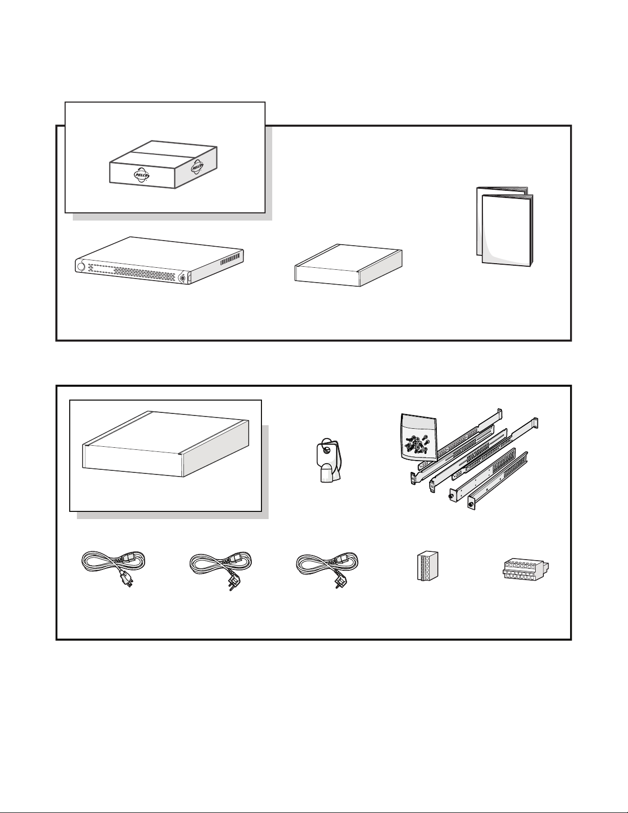
PACKAGE CONTENTS
The following diagrams show the box contents. When installing the NET5308T-EXP, refer to these diagrams.
SHIPPING BOX
NET5308T-EXP
ACCESSORY P
ACK
Figure 1. Major Package Components
SAFETY INSTRUCTIONS
INSTALLATION MANUAL
ACCESSORY PACK
FRONT BEZEL KEY
USA STANDARDT
POWER CORD
(110 VAC)
1 EA.
UK
STANDARD POWER
CORD (250 VAC)
1 EA.
2 EA.
EUROPEAN
STANDARD POWER
CORD (220 VAC)
1 EA.
RACK MOUNT KIT
RELAY TERMINAL
BLOCKS
2 EA.
ALARM TERMINAL
BLOCKS
2 EA.
Figure 2. Accessory Pack
8 C2655M-A (10/08)
Page 9
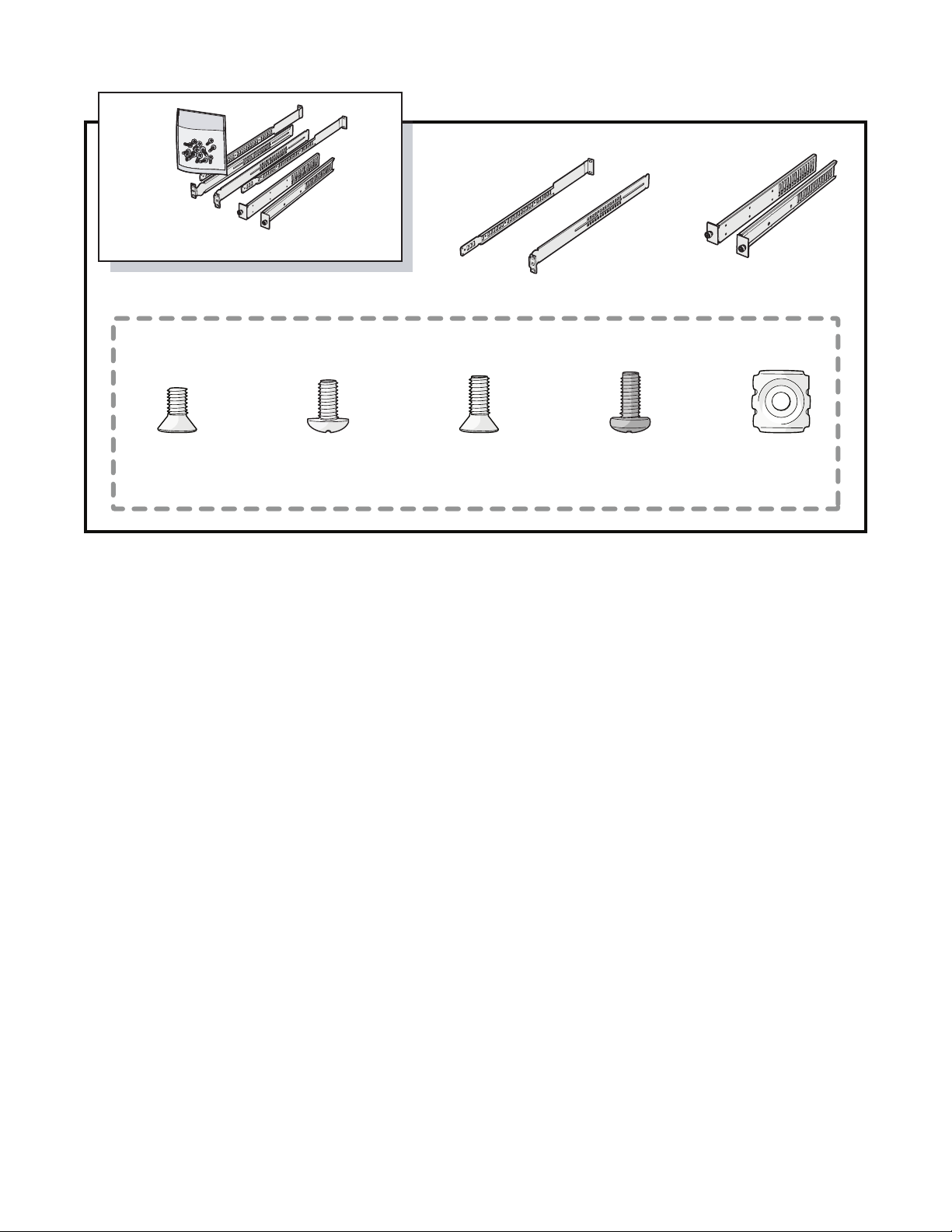
RACK MOUNT KIT
REAR MOUNT RAIL
2 EA.
SHOWN ACTUAL SIZE
PHILLIPS FLAT
HEAD SCREW,
6-32 X 0.25-INCH
6 EA.
PHILLIPS TRUSS
8-32 X 0.375-INCH
APPLICATION SCENARIO
This section illustrates one possible application scenario featuring the NET5308T multichannel video encoder. Figure 4 shows a NET5300B base
module with two NET5308T-EXP USB multichannel video encoders. This configuration uses a single Ethernet switch.
HEAD SCREW,
6 EA.
PHILLIPS FLAT
HEAD SCREW,
10-32 X 0.5-INCH
4 EA.
Figure 3. Rack Mount Kit
FRONT MOUNT RAIL
2 EA.
PHILLIPS PAN
HEAD SCREW,
10-32 X 0.5-INCH
4 EA.
CHASSIS MOUNTING
BRACKETS
1 EA.
CAGE NUT,
10-32
10 EA.
C2655M-A (10/08) 9
Page 10

USB
WS5000 SM5000
GIGABIT SWITCH
NET5300B
NET5308T-EXP #1
VCD5000
KBD5000
NVR5100
NET5308T-EXP #2
UP TO 8UP TO 8
SEB5100
Figure 4. Security Network with One NET5300B and Two NET5308T-EXPs
IMPORTANT NOTE. PLEASE READ. The network implementations in this document are shown as general representations only and are not
intended to show detailed network topologies. Your actual network will differ, requiring changes or perhaps additional network equipment to
accommodate the systems as illustrated. Please contact your local Pelco Representative to discuss your specific requirements.
10 C2655M-A (10/08)
Page 11

Product Serial Number Placement
Product serial number labels help identify your system and its factory configuration in the event that your NET5308T-EXP or its components
require service.
Two labels citing your product’s serial number are attached to your NET5308T-EXP. One large label is attached to the rear panel. A smaller label
is attached to the front panel of the unit, behind the bezel.
Because rack mounting and other installation options may obscure the factory-applied labels, a third label is provided for you to attach to your
product documentation or other product location that will not be obscured by installation.
To use this label:
1. Locate the small label on the bottom panel of your NET5308T-EXP, attached with a yellow sticker that reads, “Extra serial number labels:
remove prior to installation.”
2. Remove the yellow sticker.
3. Peel away the backing of the small label and attach it to this installation manual, other product documentation, or an unobscured product
location.
A5 A6 A7 A8
NO
Sample Text
REV
MADE IN USA
N
NC
VOLTS
Sample Text
NO
Model
MFG BY PELCO, CLOVIS, CA
03267-39-0020
N
AMPS
91KK
Sample Text
NC
Audio/Video Apparatus
SN
FREQ
50/60HZ
MODEL
PRODUCT LABEL
Figure 5. Product Serial Number Label
C2655M-A (10/08) 11
Page 12

Rack Mounting
The NET5308T-EXP mounts into an industry-standard 19-inch (48 cm) equipment rack. The NET5308T-EXP occupies one rack unit (1.75 inches or
4.5 cm) of vertical rack space. The hardware necessary to mount the NET5308T-EXP into a rack is supplied with the unit.
NOTES:
• If you installed the NET5300B on a desktop, you can also place up to two NET5308T-EXP units on top of the NET5300B. (NET5308T-EXP
units do not include rubber feet.)
• You can mount a NET5300B and up to two NET5308T-EXP units to a wall using the WM5300 wall mount. Refer to the WM5300 Wall Mount
Kit Installation manual (C2663M) for more information.
The rack must meet the following requirements:
• 19-inch (48 cm) EIA-310-D compliant (rear column required to mount the NET5300B in the same rack).
• Rack column depth: 24 to 30 inches (61 to 76 cm).
• Column-mounting hole provisions: 10-32 UNF-2B threaded holes or square window holes on front columns.
• Door systems are acceptable. Front doors must have at least 2 inches (5.1 cm) between the NET5308T-EXP front bezel and the inside of the
door. Rear doors can only be used on rack columns that are more than 26 inches (66 cm) deep.
WARNINGS:
• Secure the front and rear screws to the support rails.
• Make sure the NET5308T-EXP is level.
• Slots and openings in the cabinet provide ventilation to prevent the unit from overheating. Do not block these openings. Never place
the unit near or over a radiator or heat register. When placing the unit in a rack, be sure to provide proper ventilation. Allow at least
one rack unit (1.75 inches or 4.44 cm) of spacing between units.
To install the NET5308T-EXP in a rack:
NOTE: Figure 3 identifies each piece of hardware for this procedure.
1. If chassis mounting brackets are not attached: Attach one chassis mounting bracket to each side of the NET5308T-EXP. Use three
6-32 x 0.25-inch Phillips flat head screws for each bracket.
ATTACH
BRACKETS
(3) SCREWS
6-32 X 0.25-INCH
PHILLIPS FLAT HEAD
Figure 6. Attaching Chassis Mounting Brackets
2. Attach one front-mount rail to one rear-mount rail. Make sure the rails are mounted back to back, as shown in Figure 7. Depending on the
rack, use two or three 8-32 x 0.375-inch Phillips truss head screws for each rail set. Leave the screws loose until step 9.
12 C2655M-A (10/08)
Page 13

(3) SCREWS, 8-32 X 0.375
PHILLIPS TRUSS HEAD
Figure 7. Assembling a Support Rail
3. Repeat step 2 for the other rail set.
4. If you are installing the unit into a square-hole rack: Insert 10 cage nuts into the square-hole rack as shown in Figure 8. Align the top and
bottom cage nuts on the front racks with the top and bottom cage nuts on the rear racks.
CAGE NUT
CAGE NUT
FRONT-MOUNT RAIL
REAR-MOUNT RAIL
Figure 8. Inserting Cage Nuts
5. Attach one support rail assembly to the equipment rack in the desired location (refer to Figure 9):
NOTE: The support rail assemblies are identical and may be used on either the right or left side of the rack.
a. Position the ear of the front-mount rail against the front of the equipment rack. Align the top and bottom holes in the ear of the rail
with the threaded holes (or cage nuts) in the rack.
b. Using two 10-32 x 0.5-inch Phillips flat head screws, attach the ear of the rail to the front of the rack. Insert the screws from the
outside of the rack, pointing toward the back of the rack.
c. Adjust the rails to the correct depth of the equipment rack by sliding the rear-mount rail to the back of the equipment rack.
d. Position the ear of the rear-mount rail against the rear exterior of the equipment rack. Align the top and bottom holes in the ear of the
rail section with the threaded holes (or cage nuts) in the equipment rack.
e. Using two 10-32 x 0.5-inch Phillips pan head screws, attach the ear of the rail to the rear of the rack. Insert the screws from the
outside of the rack, pointing toward the front of the rack.
C2655M-A (10/08) 13
Page 14

RACK FRONT RACK REAR
(2) SCREWS,
10-32 X 0.5-INCH
PHILLIPS FLAT HEAD
FRONT-MOUNT RAIL
REAR-MOUNT RAIL
(2) SCREWS,
10-32 X 0.5-INCH
PHILLIPS PAN HEAD
Figure 9. Attaching Support Rails
6. Repeat step 5 for the second support rail assembly.
7. Tighten the 8-32 x 0.375-inch Phillips truss head screws that were attached to the front- and rear-mount rails in steps 2 and 3.
8. Place the unit onto the mount rails by sliding the chassis brackets onto the rails. The unit should slide in and out of the rack easily.
WARNING: When sliding out the NET5308T-EXP, be careful not to let the unit fall out of the rack.
Figure 10. Mounting the NET5308T-EXP into the Rack
14 C2655M-A (10/08)
Page 15

9. After the unit is in place, tighten the two thumbscrews to secure the unit to the rack.
THUMBSCREW
Figure 11. Tightening the Thumbscrews
C2655M-A (10/08) 15
Page 16

Connections
Familiarize yourself with the NET5308T-EXP rear panel before connecting any equipment to the unit.
1234 5678
Video Inputs 1-4
ì
Audio Inputs 1-4
î
Looping Video Outputs 1-4
ï
Relays 1-2
ñ
Alarms 1-4
ó
Video Inputs 5-8
r
Audio Inputs 5-8
s
CONNECTING TO THE NET5300B
You can connect up to two NET5308T-EXP video encoders to the NET5300B base module. This gives the NET5308T a maximum capacity of
16 inputs.
NOTES:
• Before connecting the NET5308T-EXP to its NET5300B, make sure power is off to the NET5308T-EXP.
• Do not start any NET5300B system component (NET5308T-EXP, network, camera control) until you have connected all components.
A1 A2 A3 A4 A5 A6 A7 A8
MODEL
50/60HZ
FREQ
SN
Audio/Video Apparatus
NO
Sample Text
91KK
AMPS
C
03267-39-0020
MFG BY PELCO, CLOVIS, CA
Model
NC
Sample Text
VOLTS
NO
C
MADE IN USA
REV
Sample Text
NC
Figure 12. NET5308T-EXP Rear Panel
Looping Video Outputs 5-8
t
Relays 3-4
u
Alarms 5-8
~í
Power
~â
SEQ Monitor
~ä
USB 2.0
~ã
SEC
NO
C
NC
NO
C
NC
100-200 VAC - 50/60 HZ
0.7 AMP
Two of the three USB ports on the NET5300B rear panel correspond to a specific set of video inputs (refer to Table A on this page and Figure 13
on page 17). Each NET5300B includes two different colored USB cables and a matching set of colored stickers. Use them on the NET5308T-EXP
to match each NET5308T-EXP to its specific video inputs.
Table A. NET5300B/NET5308T-EXP USB Connectors and Colors
NET5300B
USB Port
Video
Inputs
NET5308T-EXP USB
Cable Color
1 1–8 #1 Red
2 9–16 #2 Yellow
NOTES:
• The USB ports on the NET5300B rear panel are numbered from bottom to top: port 1 is at the bottom; port 2 is at the top.
• Connecting a NET5308T-EXP to USB port 1 assigns camera numbers 1–8 to the video inputs on that NET5308T-EXP.
To connect the NET5308T-EXP to its NET5300B base module:
1. Select the USB cable (red or yellow) that corresponds to the video inputs. Two different colored USB cables are included with each
NET5300B.
2. Connect the narrow “B” connector of the USB cable to the USB connector on the NET5308T-EXP rear panel.
3. Apply a matching colored sticker (red or yellow) next to the USB connector on the NET5308T-EXP rear panel. This identifies the USB cable
(red or yellow) that should be connected to this NET5308T-EXP.
4. Connect the wide “A” connector of the USB cable to the corresponding USB connector on the NET5300B rear panel.
16 C2655M-A (10/08)
Page 17

5. Apply a matching colored sticker (red or yellow) next to the USB connector on the NET5300B rear panel. This identifies the USB cable (red
or yellow) that should be connected to this NET5308T-EXP.
APPLY
RED LABEL
USB “A” CONNECTOR
APPLY
YELLOW LABEL
NET5300B
YELLOW USB CABLE
RED USB CABLE
APPLY
YELLOW LABEL
APPLY
RED LABEL
USB “B”
CONNECTOR
NO
N
NC
NO
N
NC
A5 A6 A7 A8
SEC
NET5308T-EXP #2
USB “B”
CONNECTOR
NO
N
NC
NO
N
NC
A5 A6 A7 A8
SEC
NET5308T-EXP #1
Figure 13. Connecting an NET5308T-EXP to a NET5300B
6. If necessary, repeat steps 1–5 for other NET5308T-EXP encoders.
7. Start the NET5308T-EXP.
8. Start the NET5300B (refer to the NET5300B Installation manual for more information).
When the NET5308T-EXP is first started, the unit status light blinks green until the NET5300B recognizes it and puts it into service.
CONNECTING VIDEO INPUT AND OUTPUT DEVICES
The NET5308T-EXP offers both analog video input and looping video output for eight video devices.
CAMERAS
1234 5678
LOOPING
VIDEO
MONITOR
Before installing the NET5308T-EXP, make sure the distance from the unit to each video device is less than the maximum distance for the coaxial
cable. Refer to Table B for maximum video coaxial cable distances.
A1 A2 A3 A4 A5 A6 A7 A8
MODEL
50/60HZ
FREQ
SN
Audio/Video Apparatus
NO
Sample Text
91KK
AMPS
C
03267-39-0020
MFG BY PELCO, CLOVIS, CA
Model
NC
Sample Text
VOLTS
NO
C
MADE IN USA
REV
Sample Text
NC
Figure 14. Video Inputs and Outputs
SEQ
MONITOR
SEC
NO
C
NC
NO
C
NC
100-200 VAC - 50/60 HZ
0.7 AMP
C2655M-A (10/08) 17
Page 18

Table B. Video Coaxial Cable Requirements
Cable Type* Maximum Distance
RG59/U 750 ft (229 m)
RG6/U 1,000 ft (305 m)
RG11/U 1,500 ft (457 m)
*Cable requirements:
75-ohm impedance
All-copper center conductor; steel-center conductor cable may
result in poor performance
All-copper braided shield with 95% braid coverage
CONNECTING VIDEO INPUT
The NET5308T-EXP automatically detects the video standard (PAL or NTSC) when you connect a video input. It accepts both color and black-white
analog video. Use the Endura workstation to enable or disable video termination for each video input. Video termination is enabled by default.
NOTES:
• Enabling line lock on cameras may cause video distortion. There may be noise in the camera’s power source. If video from one or more
cameras is distorted, Pelco recommends disabling line lock on the camera as your first troubleshooting step.
• If a video distribution amplifier, such as a CM9760-MDA, is installed between the video source and the NET5308T-EXP, do not set the
output video level above 1 Vp-p.
To connect each video input:
1. Connect a coaxial cable to the camera or other analog video source.
2. Connect the coaxial cable to the video in connector on the rear panel.
NOTE: You may have to use a BNC installation tool to connect coaxial cables to the rear panel.
After connecting the coaxial cables to the NET5308T-EXP, use the SEQ video output to verify each video source (refer to Connecting Sequence
Monitor on page 24).
CAMERA CONTROL: COAXITRON
Coaxitron is Pelco’s up-the-coax technology. It requires only a coaxial cable and no other wiring or equipment. When the NET5308T-EXP receives
a camera control command, it transmits that command up the coaxial cable to the PTZ device. Coaxitron is a single-direction protocol; the PTZ
device cannot return any data to the unit.
To enable Coaxitron operation, connect the PTZ device to the video input on the NET5308T-EXP. Since Coaxitron is disabled by default for each
camera, use the Endura workstation to enable it on the specific video inputs.
CAMERA CONTROL: PELCO D/PELCO P PROTOCOL
The NET5300B and NET5308T-EXP together support Pelco D (4-wire) and Pelco P (2-wire) protocols. These protocols use a serial interface to
transmit commands to the PTZ device over separate control wires. Refer to Connecting Serial PTZ Devices in the Endura NET5300B Multichannel
Video Encoder Base Module Installation manual (C2614M) for more information.
18 C2655M-A (10/08)
Page 19

CONNECTING LOOPING VIDEO
The NET5308T-EXP supports looping video. It passes the video input to a monitor or other analog video device.
To use looping video:
1. Connect a coaxial cable to the video out connector on the rear panel.
NOTE: You may have to use a BNC installation tool to connect coaxial cables to the rear panel.
2. Connect the other end of the coaxial cable to the analog device.
3. After installation, use the Endura workstation to disable video termination for the video channel.
4. If looping video to additional devices, disable video termination (Hi-Z) on each device. Enable termination (75 ohms) on the last device.
NOTES:
• If you do not terminate the video signal at the last device in the series, ghosting or other imperfections may appear in the video signal.
• During a power loss, the video termination settings may be lost. As a result, video imperfections may appear on devices that receive
looping video from the NET5308T-EXP. If this is not acceptable in your installation, use alternate looping methods.
CONNECTING AUDIO
The NET5308T-EXP supports eight audio inputs, each associated with the main video stream for its corresponding video input. The unit encodes
audio and video signals simultaneously. This lets you control audio at the monitored location.
The unit supports line level inputs. Microphones must be amplified for best results.
MICROPHONES
AUDIO PREAMP
1234
A1
MODEL
50/60HZ
FREQ
SN
Audio/Video Apparatus
NO
Sample Text
91KK
AMPS
C
03267-39-0020
MFG BY PELCO, CLOVIS, CA
Model
NC
Sample Text
VOLTS
NO
C
MADE IN USA
REV
Sample Text
NC
Figure 15. NET5308T-EXP Audio Connections
To implement audio:
1. Make sure your audio input device matches the 1 Vp-p line input level (+4dB, 1.228 V maximum). If the audio source does not match this
specification, audio distortion problems may occur.
2. Wire the audio input device to the 3.5 mm monaural audio plug as follows:
Connector Tip Signal high
Connector
Common
Sleeve
3. Insert the audio plug into the audio connector for the video channel on the NET5308T-EXP rear panel.
C2655M-A (10/08) 19
Page 20

CONNECTING RELAY DEVICES
The NET5308T-EXP supports up to four relay devices. Use them to trigger external devices. The unit supports both momentary and continuous
relay operation, either normally open or normally closed.
You can operate the relay interactively, during an active connection, or automatically to coincide with certain events. Typical applications include
activating a door, gate, or lock, or switching on lights or other electrical devices.
WARNING: Do not exceed the maximum ratings: 30 VDC, 2 A; 125 VAC, 0.5 A.
When wiring the connector:
• Use 16 to 26 AWG (0.14 to 1.5 mm
electrostatic discharge (ESD).
• Strip the relay control wire to 0.3 inches (7.6 mm).
• Insert the wire far enough into the connector so that the metal is not exposed.
• When using a relay with a higher load, install an external, more powerful relay.
The unit includes two 6-pin relay control terminal blocks. These blocks have tension clamps. Use a small screwdriver to open the clamp for a
particular lead. Figure 16 shows how to wire the relay control terminal block and connect it to the NET5308T-EXP.
NOTE: The terminal block is keyed. It attaches only one way to the NET5308T-EXP.
2
) wire that is rated for 250 V or higher. The insulation must be thick enough to protect against
Figure 16. Relay Control Terminal Block
Table C identifies the pin assignments for the relay control terminal blocks. On the terminal block, pin 1 is the top lead (refer to Figure 16).
Table C. Relay Control Pin Assignments
Relay Pin Label
1, 3 1 NO
2C
3NC
2, 4 4 NO
5C
6NC
Lead
Normally Open
Common
Normally Closed
Normally Open
Common
Normally Closed
Figure 17 shows how to wire the relay with its power source to the NET5308T-EXP (refer to Table C on page 20 for the specific connector pin
assignments).
20 C2655M-A (10/08)
Page 21

CONNECTING ALARMS
The NET5308T-EXP offers eight alarm inputs for external signaling devices, such as door contacts or motion detectors. Each alarm input can be
either normally open or normally closed, either supervised or unsupervised.
Once configured, an alarm input can invoke many different activities, including triggering a relay device, sending an alert to a security office,
changing the video recording settings, and storing pre-alarm video to an NVR5100 Series network video recorder or other Endura video recorder.
You can connect switches or contacts directly to the unit without a separate power supply.
EXTERNAL
FUSE
MAX: 30 VDC, 2 A
NO
NO
C
NC
NO
C
NC
C
A5 A6 A7 A8
125 VAC, 0.5 A
100-200 VAC - 50/60 HZ
0.7 AMP
LOAD:
LIGHT/SIREN
POWER
Figure 17. Connecting a Relay Device
SUPERVISED ALARMS
When an alarm is configured as a supervised alarm, the NET5308T-EXP maintains a constant electrical current through the alarm circuit (5.0 VDC,
10 kohms), including a 10-kohm resistor. If the resistance changes, due to an electrical short or a bypass, the voltage fluctuates from its normal
state. Therefore, the unit triggers an alarm.
Figure 18 illustrates the alarm and no alarm conditions of a supervised alarm input. Whether the alarm is normally closed or normally open,
neither a cut nor a bypass can defeat these alarms.
NORMALLY CLOSED
NO ALARM
GND
ALARM
GND
ALARM
GND
ALARM
GND
10 K
10 K
10 K
10 K
Ω
Ω
Ω
CUT
Ω
BYPASS
+V
+V
+V
+V
Figure 18. Supervised Alarm Conditions
NO ALARM
GND
ALARM
GND
ALARM
GND
ALARM
GND
NORMALLY OPEN
10 K
10 K
10 K
CUT
10 K
BYPASS
Ω
+V
Ω
+V
Ω
+V
Ω
+V
C2655M-A (10/08) 21
Page 22

Figure 19 illustrates the wiring configuration for supervised alarm inputs.
NORMALLY CLOSED NORMALLY OPEN
10 K
10 K
Ω
Ω
Figure 19. Supervised Alarm Input Wiring
UNSUPERVISED ALARMS
When an alarm is configured as an unsupervised alarm, the NET5308T-EXP triggers an alarm only when the normal alarm state (open or closed)
changes.
Figure 20 illustrates the alarm and no alarm conditions of an unsupervised alarm input. A normally closed alarm input can be defeated with a
bypass. A normally open input can be defeated with a cut.
NORMALLY CLOSED
NO ALARM
GND
ALARM
GND
ALARM
GND
NO ALARM
GND
BYPASS
CUT
+V
+V
+V
+V
NO ALARM
GND
ALARM
GND
NO ALARM
GND
ALARM
GND
NORMALLY OPEN
BYPASS
CUT
+V
+V
+V
+V
Figure 20. Unsupervised Alarm Conditions
Figure 21 illustrates the wiring configuration for unsupervised alarm inputs.
NORMALLY CLOSED NORMALLY OPEN
Figure 21. Unsupervised Alarm Input Wiring
ALARM CONNECTIONS
The unit includes two 8-pin alarm terminal blocks. These blocks have tension clamps. Use a small screwdriver to open the clamp for a particular
lead. Figure 22 shows how to wire the alarm terminal block and connect it to the NET5308T-EXP.
When wiring the connector:
• Use 20 to 28 AWG (0.08 to 0.5 mm2) wire that is rated for 250 V or higher. The insulation must be thick enough to protect against
electrostatic discharge (ESD).
• Strip the alarm wire to 0.31 inches (8 mm).
• Insert the wire far enough into the connector so that the metal is not exposed.
The terminal block is keyed. It attaches only one way to the NET5308T-EXP.
22 C2655M-A (10/08)
Page 23

Figure 22. Alarm Terminal Block
Table D identifies the pin assignments for the terminal block. On the terminal block, pin 1 is on the left (refer to Figure 22).
Table D. Alarm Pin Assignments
Pin Label Lead
1A1Alarm 1
2Ground
3A2Alarm 2
4Ground
5A3Alarm 3
6Ground
7A4Alarm 4
8Ground
These pins, labels, and leads also correspond to alarms 5–8 on the other alarm terminal block.
To prevent false alarms on unused alarm inputs, configure or connect (jumper) unused alarm inputs using one of the following options:
• Configure the alarm input as unsupervised and normally open on the Endura workstation. You do not have to connect the alarm input. This
is the default.
• Configure the alarm input as unsupervised and normally closed on the Endura workstation. Then connect the alarm input directly to its
ground. For example, connect pin 1 (Alarm 1) to pin 2 (Ground) if not using Alarm 1.
• Configure the alarm input as supervised and either normally open or normally closed. Then connect the alarm input directly to its ground
through a 10-kohm resistor. For example, if not using Alarm 1, connect pin 1 (Alarm 1) to a 10-kohm resistor; then connect the resistor to
pin 2 (Ground).
Figure 23 shows how to wire an alarm device to the Alarm 5 input (refer to Table D on page 23 for the specific connector pin assignments).
C2655M-A (10/08) 23
Page 24

CONNECTING POWER
The power supply incorporated into the NET5308T-EXP is tested and certified for high reliability applications. The unit has an autoranging power
supply that adapts automatically to voltages between 100 VAC and 240 VAC (50/60 Hz).
For greater reliability, you can also install an uninterruptible power supply (UPS) (not supplied). UPS devices maintain a limited amount of backup
battery power in case the main power fails. The UPS should have a minimum rating of 200 VA for one NET5300B and two NET5308T-EXP units.
To connect power:
1. Connect one of the supplied US, European, or UK standard power cords to rear of the unit.
2. Connect the cord to the appropriate power source.
Refer to Unit Startup on page 26 to power up the unit.
A5
A5 A6 A7 A8
NO
C
NC
NO
C
NC
100-200 VAC - 50/60 HZ
0.7 AMP
Figure 23. Connecting Alarms
CONNECTING SEQUENCE MONITOR
Use the SEQ output connector during installation to display video sequentially from each video input. The unit displays each channel for two
seconds. It displays a black screen for channels without video. Use this feature to verify camera installation.
To display video from each connected video source:
1. Connect a video monitor to the SEQ output connector.
2. Start the NET5308T-EXP, the monitor, and each video source.
3. Verify the video from each source and troubleshoot as necessary.
24 C2655M-A (10/08)
Page 25

Operation
Refer to the WS5000 operation manual (C2624M) for details on how to access and configure the video inputs on the NET5308T-EXP. Configure
the NET5300B before you configure any video inputs on the NET5308T-EXP.
NOTE: To make sure that all diagnostic messages will appear to a system operator, leave at least one Endura workstation or VCD5000 video
console display running at all times.
FRONT PANEL CONTROLS AND INDICATORS
Figure 24. Front Panel Layout (Without Bezel)
Pelco badge (power): The Pelco badge glows blue when the unit has power. If the front bezel is open, this indicator glows white.
ì
USB Video Operation (two per input): The USB video operation indicator shows the status for each video input. The left indicator
î
shows the status of the primary video stream; the right indicator shows the status of the secondary video stream.
• Green: Camera video is present at the video input connector. Video is streaming correctly.
• Blink On: When the indicator is not lit, but blinks about once a second, camera video is present at the video input connector, but
video is not streaming. The video stream may have been disabled by a system operator or there may be a different problem. (Refer to
Troubleshooting on page 27 for possible solutions.)
• Blink Off: When the indicator is lit, but double blinks off about once a second, there is video loss at the video input connector;
however, the video stream is still active. Check the video input device.
• Off: The video stream is inactive.
Power Button: Use the power button to turn the unit on and off (refer to Unit Startup and Unit Shutdown on page 26).
ï
USB Video Status (unit): The unit USB video status indicator shows the video status for all video inputs for the unit. Status is
ñ
indicated as follows:
• Off: The video on all channels is functioning properly.
• Red: One or more video channels are not operating correctly, either because of video loss or a channel transmission problem. Open
the front bezel to identify the affected channels.
Unit Status: Unit status is indicated by one of the following three colors:
ó
• Green (solid): The unit is functioning normally.
• Green (blink): The unit has been started but has not been connected to the NET5300B.
• Amber: The unit is in configuration mode (only when NET5300B is updating unit software).
• Red: The unit has an error condition (refer to Troubleshooting on page 27).
C2655M-A (10/08) 25
Page 26

UNIT STARTUP
To start the unit:
1. Unlock and open the bezel cover. Be careful not to drop the bezel cover; it is not attached directly to the unit.
2. Press the power button until it clicks. The power indicator glows.
3. Close and lock the bezel cover.
UNIT SHUTDOWN
To shut down the unit:
1. Unlock and open the bezel cover. Be careful not to drop the bezel cover; it is not attached directly to the unit.
POWER BUTTON
Figure 25. Opening the Front Bezel Cover
2. Press and release the power button.
3. Close and lock the bezel cover.
26 C2655M-A (10/08)
Page 27

Troubleshooting
If the following instructions fail to solve your problem, contact Pelco Product Support at 1-800-289-9100 or +1-559-292-1981 for assistance.
Access the properties dialog boxes for the camera on the Endura workstation (refer to the WS5000 operation manual [C2624M]). Then note the
following before calling Pelco:
• Unit serial number: on the product label
• Software version: located in the Advanced Properties window
WARNING: Do not try to repair the unit yourself. Opening it immediately voids any warranty. Leave maintenance and repairs to qualified
technical personnel. Exchange the defective unit and return it for repair.
Problem Possible Causes Suggested Remedy
Unit not ready Power turned off Check that the power indicator is lit.
No video transmission; USB video status
indicator is red
Poor analog video or ghosting Termination not set correctly From an Endura workstation, disable video termination for
No looping video on local monitor Faulty cable connections Check all leads, plugs, contacts, and connections.
Unit status indicator is red Unit fan failure Replace the NET5308T-EXP and have it checked by Pelco.
The unit is not ready for operation after
firmware upload
Table E. Troubleshooting the NET5308T-EXP
Faulty cable connections Check all leads, plugs, contacts, and connections.
Network connectivity issues Contact your network administrator.
Video loss at camera Check all camera connections. Connect local monitor and
check camera function.
Defective camera Connect local monitor and check camera function.
NET5308T-EXP connected to
incorrect USB connector on
NET5300B rear panel
Defective NET5308T-EXP Check camera on a different NET5308T-EXP.
Video termination is enabled From an Endura workstation, enable video termination.
System cannot activate the unit
encoder channel
Voltage failure during programming
of update file
Connect USB cable to correct connector.
looping video; enable it if not using looping video.
Replace the NET5308T-EXP and have it checked by Pelco.
Replace the NET5308T-EXP and have it checked by Pelco.
C2655M-A (10/08) 27
Page 28

Specifications
MODEL NUMBER
NET5308T-EXP Multichannel dual stream video encoder that encodes video and audio and that controls data for
VIDEO/AUDIO
Video Standards NTSC/PAL/EIA/CCIR composite
Video Coding MPEG-4
Video Streams 16, simultaneous, 2 per input
Video Resolutions NTSC
4CIF 704 x 480 704 x 576
2CIF 704 x 240 704 x 288
CIF 352 x 240 352 x 288
QCIF 176 x 120 178 x 144
Video Inputs 8, BNC, looping, 75 ohms, 0.5-1 Vp-p
Video Output 1, BNC, 1 Vp-p
Video Termination Software controlled
Audio Encoding G.711 speech codec
Audio Bit Rate 64 kbps
Audio Input 1 Vp-p (line level), 1 kohms
Audio Connectors 8, 3.5 mm monaural
Audio Inputs Line in
transmission over a USB 2.0 link to a NET5300B base module
PAL
Connector TipSignal high
Connector SleeveCommon
PTZ CONTROL
PTZ Interface Video in
PTZ Protocols Coaxitron (NET5308T-EXP), Pelco D and Pelco P (NET5300B)
ALARMS/RELAYS
Alarm Inputs 8, programmable, 5.0 VDC, 10 kohms, triggered, CM9760-ALM compatible
Relay Outputs 4, form-C relay, 30 VDC 2 A or 125 VAC 0.5 A, CM9760-REL compatible
VIDEO ACTIVITY DETECTION
Zones 3 plus background zone
Zone Types Any shape, user-definable in 16 x 16 pixel blocks
Sensitivity Adjustable
AUXILIARY INTERFACES
NET5300B 1, USB 2.0 “B” Connector
Alarms 2, 8-pin terminal block
Relays 2, 6-pin terminal block
FRONT PANEL INDICATORS/FUNCTIONS
Power Blue
USB Video Status Red
USB Video Operation Green
Unit Status Green, amber, red
28 C2655M-A (10/08)
Page 29

POWER
Power Input 100–240 VAC, 50/60 Hz, 0.7A, autoranging
Cable Type 1 USA (117 VAC), 1 European (220 VAC), 1 UK (250 VAC)
All, 3 prongs, molded connector, 6 ft (1.8 m) cord
Power Consumption (maximum) 40 W, 137 BTU/H
ENVIRONMENTAL
Operating Temperature 50° to 95°F (10° to 35°C) at unit air intake (front of unit)
Storage Temperature -40° to 149°F (-40° to 65°C)
Operating Humidity 20% to 80%, noncondensing
Maximum Humidity Gradient 10% per hour
Operating Altitude -50 ft to 10,000 ft (-16 m to 3,048 m)
Operating Vibration 0.25 G at 3 Hz to 200 Hz at a sweep rate of 0.5 octave/minute
NOTE: The temperature at the unit air intake can be significantly higher than room temperature. Temperature is affected by rack configuration,
floor layout, air conditioning strategy, and other issues. To prevent performance failure and unit damage, make sure the temperature at the unit is
continuously within the operating temperature range.
PHYSICAL
Construction Steel cabinet
Finish
Bezel Gray metallic with black end caps
Chassis Black matte finish
Dimensions 16.7" D x 17.0" W x 1.7" H
(42.4 x 43.2 x 4.3 cm)
Unit Weight 13.35 lb (6.1 kg)
Mounting Rack, 1 RU per unit
(Rack ears and screws provided)
STANDARDS/ORGANIZATIONS
• Pelco is a member of the MPEG-4 Industry Forum
• Pelco is a member of the Universal Plug and Play (UPnP) Forum
• Pelco is a member of the Universal Serial Bus (USB) Implementers Forum
• Pelco is a contributor to the International Standards for Organization/Electrotechnical Commission (ISO/IEC) Joint Technical Committee 1
(JTC1), “Information Technology,” Subcommittee 29, Working Group 11
• Compliance, ISO/IEC 14496 standard (also known as MPEG-4)
• Compliant with International Telecommunication Union (ITU) Recommendation G.711, “Pulse Code Modulation (PCM) of Voice Frequencies”
(Design and product specifications subject to change without notice.)
C2655M-A (10/08) 29
Page 30

Page 31

PRODUCT WARRANTY AND RETURN INFORMATION
WARRANTY
Pelco will repair or replace, without charge, any merchandise proved defective in
material or workmanship for a period of one year after the date of shipment.
Exceptions to this warranty are as noted below:
• Five years on fiber optic products and TW3000 Series unshielded twisted pair
(UTP) transmission products.
• Three years on Spectra
• Three years on Genex
• Three years on DX Series digital video recorders, DVR5100 Series digital video
recorders, Digital Sentry
recorders, NVR300 Series network video recorders, and Endura
distributed network-based video products.
• Three years on Camclosure
the CC3701H-2, CC3701H-2X, CC3751H-2, CC3651H-2X, MC3651H-2, and
MC3651H-2X camera models, which have a five-year warranty.
• Three years on EH1500 Series enclosures.
• Three years on PMCL200/300/400 Series LCD monitors.
• Two years on standard motorized or fixed focal length lenses.
• Two years on Legacy
Series fixed dome products.
• Two years on Spectra III
including when used in continuous motion applications.
• Two years on Esprit Ti and TI2500 Series thermal imaging products.
• Two years on Esprit and WW5700 Series window wiper (excluding wiper blades).
• Two years (except lamp and color wheel) on Digital Light Processing (DLP
displays. The lamp and color wheel will be covered for a period of 90 days. The
air filter is not covered under warranty.
• Two years on Intelli-M
• One year (except video heads) on video cassette recorders (VCRs). Video heads
will be covered for a period of six months.
• Six months on all pan and tilts, scanners, or preset lenses used in continuous
motion applications (preset scan, tour, and auto scan modes).
Pelco will warrant all replacement parts and repairs for 90 days from the date of
Pelco shipment. All goods requiring warranty repair shall be sent freight prepaid
to a Pelco designated location. Repairs made necessary by reason of misuse,
alteration, normal wear, or accident are not covered under this warranty.
®
IV products.
®
Series products (multiplexers, server, and keyboard).
®
Series hardware products, DVX Series digital video
®
and Pelco-branded fixed camera models, except
®
, CM6700/CM6800/CM9700 Series matrix, and DF5/DF8
™
, Spectra Mini, Esprit®, ExSite®, and PS20 scanners,
®
eIDC controllers.
®
Series
Pelco assumes no risk and shall be subject to no liability for damages or loss
resulting from the specific use or application made of the Products. Pelco’s liability
for any claim, whether based on breach of contract, negligence, infringement of
any rights of any party or product liability, relating to the Products shall not exceed
the price paid by the Dealer to Pelco for such Products. In no event will Pelco be
liable for any special, incidental, or consequential damages (including loss of use,
loss of profit, and claims of third parties) however caused, whether by the
negligence of Pelco or otherwise.
The above warranty provides the Dealer with specific legal rights. The Dealer may
also have additional rights, which are subject to variation from state to state.
If a warranty repair is required, the Dealer must contact Pelco at (800) 289-9100 or
(559) 292-1981 to obtain a Repair Authorization number (RA), and provide the
following information:
1. Model and serial number
2. Date of shipment, P.O. number, sales order number, or Pelco invoice number
3. Details of the defect or problem
If there is a dispute regarding the warranty of a product that does not fall under
the warranty conditions stated above, please include a written explanation with
the product when returned.
Method of return shipment shall be the same or equal to the method by which the
item was received by Pelco.
®
RETURNS
)
To expedite parts returned for repair or credit, please call Pelco at (800) 289-9100
or (559) 292-1981 to obtain an authorization number (CA number if returned for
credit, and RA number if returned for repair) and designated return location.
All merchandise returned for credit may be subject to a 20 percent restocking and
refurbishing charge.
Goods returned for repair or credit should be clearly identified with the assigned
CA or RA number and freight should be prepaid.
The materials used in the manufacture of this document and its components are compliant to the requirements of Directive 2002/95/EC.
This equipment contains electrical or electronic components that must be recycled properly to comply with Directive 2002/96/EC of the European Union
regarding the disposal of waste electrical and electronic equipment (WEEE). Contact your local dealer for procedures for recycling this equipment.
REVISION HISTORY
Manual # Date Comments
C2655M 12/06 Original version.
C2655M-A 10/08 Revised installation instructions, updated temperature specifications, and updated warranty.
Pelco, the Pelco logo, Coaxitron, Camclosure, Digital Sentry, Endura, the Endura logo, Esprit, ExSite, Genex, Intell i-M, Legacy, and Spectra are registered trade marks of Pelco, Inc. ©Copyright 2008, Pelco, Inc. All rights rese rved.
Spectra III is a trademark of Pelco, Inc.
DLP is a registered trademark of Texis Instruments, Inc.
Page 32

Pelco, Inc. Worldwide Headquarters 3500 Pelco Way, Clovis, California 93612 USA
USA & Canada Tel: (800) 289-9100 Fax: (800) 289-9150
International Tel: +1 (559) 292-1981 Fax: +1 (559) 348-1120
www.pelco.com
 Loading...