

Page 1
QUICK START GUIDE
™
®
NET104A Multimedia
Transmission System
C2900M-QS (9/02)
Page 2

2 C2900M-QS (9/02)
Page 3

BEFORE YOU BEGIN
Installation of PelcoNet™ requires support from your network administrator. Contact your
administrator to assist with STEP 2 – Configuring PelcoNet Using HyperTerminal. Write down the
following information from your network administrator:
1. A unique IP address for each PelcoNet unit
____.____.____.____ ____.____.____.____
2. The subnet mask for each IP address
____.____.____.____ ____.____.____.____
3. The default gateway for each address
____.____.____.____ ____.____.____.____
4. The IP address of the mail server
____.____.____.____ ____.____.____.____
C2900M-QS (9/02) 3
Page 4
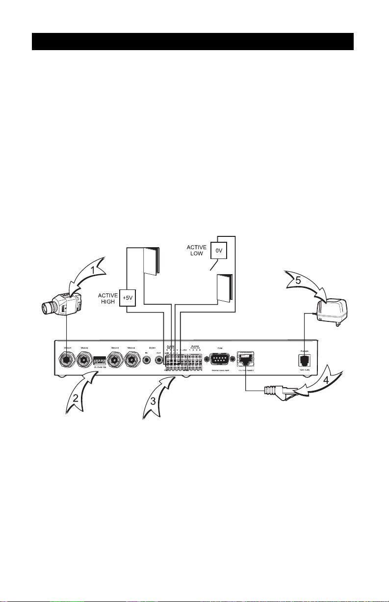
STEP 1A
CONNECTING THE TRANSMITTER – NET104A
1. Plug in cameras or other video sources with composite NTSC or PAL output.
2. Set DIP switches to position 75 OHM ON (down) to terminate the inputs when the video signal
is not connected to additional video equipment through a T-connection.
3. Connect additional items such as alarms, audio, etc.
4. Connect to the Ethernet network using a standard UTP Cat5 cable with RJ-45 connectors.
5. Insert the power cable plug into the power jack until it latches. Insert the power supply into the
wall socket.
4 C2900M-QS (9/02)
Page 5

STEP 1B
CONNECTING THE RECEIVER – NET101R/R-A
NOTE: Skip this step if a receiver will not be used.
1. Plug in the supplied power adapter to power-up the NET101R/R-A.
2. Attach the monitor to the BNC connector VIDEO OUT on the receiver.
3. Connect a network cable from the port labeled ETHERNET/UTP on the NET101R/R-A to the
network.
4. Connect the port labeled TRANSPARENT DATA to the correctly wired PV130 adapter, and
connect keyboards (for example, KBD4000, CM9760-KBD, KBD300A), if any.
PELCONET FRONT PANEL
2
DIRECT
5
MODE
6
7
STRAIGHT CABLE
4
00684
PELCONET BACK PANEL
3
1
12 VDC
PV130
4800, 8, NONE, 1
RD(A)
RD(B)
12 VAC
KBD300
4
3
2
18
C2900M-QS (9/02) 5
Page 6

STEP 2
CONFIGURING PELCONET USING HYPERTERMINAL
NOTE: If you do not want to configure PelcoNet using HyperTerminal, refer to the PelcoNet manual
for instructions on configuring PelcoNet using a web browser.
All commands consist of single characters you type inside the terminal window. Enter just one
command at a time. (Refer to the Terminal Command Reference table in the PelcoNet manual for
commands.)
1. Connect the D-sub COM jack on the NET104A to a free serial port on the PC. (Ensure the PC’s
COM port is set up properly [default parameters are 19200 baud, 8N1] and that the local
terminal echo is disabled.)
2. Click the Start button on the desktop, and select Programs from the Start menu.
6 C2900M-QS (9/02)
Page 7

3. Highlight Accessories. Click HyperTerminal.
2
4. Double-click Hypertrm.exe. This opens the HyperTerminal application.
3
00686
4
00687
C2900M-QS (9/02) 7
Page 8

5. Type the name for the new connection in the field labeled Name. Click OK.
5
6. Change the field labeled Connect using to the COM port of the computer to which you have
connected the serial cable. Click OK.
6
7. Change the field labeled Bits per second to 19200.
8 C2900M-QS (9/02)
Page 9

8. Change the field labeled Flow control to None. Click OK.
7
8
9. You are now ready to configure PelcoNet. Hold the Shift key and press the ? key. This brings up
the Help menu.
10. Press the I key to set the IP address. Type the new IP address PelcoNet will be using on the
network. Press Enter.
11. Press the S key to set the subnet mask. Type the new subnet mask. Press Enter.
12. Press the G key to set the gateway IP address. Type the new gateway IP address. Press Enter.
9
10
11
12
13. Close HyperTerminal. If prompted to save settings, click OK.
C2900M-QS (9/02) 9
Page 10

STEP 3
FINAL CONNECTION SETTINGS
NOTE: Skip this step if a NET101R/R-A receiver will not be used.
NOTE: If you changed the transmitter and receiver IP addresses in STEP 2, then use the new ad-
dresses to connect to the units. Also use the new addresses to make changes to any settings. If no
changes were made to the IP addresses in STEP 2, use the default address for the transmitter
(192.168.0.1) and the default address for the receiver (192.168.0.2).
1. Install Internet Explorer® 5.0 (if you have not already done so) from the CD supplied with
PelcoNet on to a computer connected to the network.
2. Open Internet Explorer 5.0.
3. Type the receiver’s IP address in the address field, and then press Enter to connect to the
receiver.
4. Click the Setup icon.
5. Click Alarm Settings to bring up the Alarm Settings page.
10 C2900M-QS (9/02)
Page 11

6. Click Connects to Yes. Click Set.
7. Type the transmitter’s IP address in the box labeled Live Video Receive IP. Click Set.
8. Click Live video auto connect to On. Click Set.
6
7
8
9. Installation is now complete.
® Pelco and the Pelco logo are registered trademarks of Pelco.
® Internet Explorer is a registered trademark of Microsoft Corporation.
REVISION HISTORY
Manual # Date Comments
C2900M-QS 9/02 Original version.
C2900M-QS (9/02) 11
™ PelcoNet is a trademark of Pelco.
© Copyright 2002, Pelco. All rights reserved.
Page 12

®
World Headquarters
3500 Pelco Way
Clovis, California 93612 USA
USA & Canada
Tel: 800/289-9100
Fax: 800/289-9150
International
Tel: 1-559/292-1981
Fax: 1-559/348-1120
www.pelco.com
ISO9001
Orangeburg, New York Las Vegas, Nevada Eindhoven, The Netherlands Wokingham, United Kingdom Montreal, Canada
 Loading...