

Page 1
®
MR4000/MRU
Monitor Mounts
Installation/Operation Manual
C233M-G (8/95)
Pelco • 300 W. Pontiac Way, Clovis, CA 93612-5699 • USA • (800) 289-9100 or (1-559) 292-1981
FAX (800) 289-9150 or (1-559) 292-3827 • DataFax (800) 289-9108 or (1-559) 292-0435
International customers call (1-559) 292-1981 or FAX (1-559) 348-1120
Page 2

CONTENTS
Section Page
1.0 GENERAL..................................................................................................1
1.1 IMPORTANT SAFEGUARDS AND WARNINGS ...............................1
2.0 DESCRIPTION ..........................................................................................2
3.0 INSTALLATION..........................................................................................3
3.1 MR4000 ASSEMBLY .........................................................................3
3.1.1 Monitor Assembly (See Figure 1) ..........................................3
3.1.2 Hanger Assembly (See Figure 2)...........................................3
3.1.3 Mounting the Hanger Assembly.............................................4
3.1.4 Monitor Mounting ...................................................................4
3.2 MRU ASSEMBLY INSTRUCTIONS...................................................5
3.2.1 Hanger Assembly...................................................................5
3.2.2 Mounting the Hanger Assembly.............................................5
3.2.3 Monitor Mounting ...................................................................5
4.0 EXPLODED ASSEMBLY ...........................................................................6
5.0 SPECIFICATIONS .....................................................................................7
6.0 WARRANTY AND RETURN INFORMATION ............................................8
10 Pelco Manual C233M-G (8/95)ii
Page 3

LIST OF ILLUSTRATIONS
Figure Page
1 Monitor Assembly ..............................................................................3
2 MR4000 Exploded Assembly.............................................................6
3 Dimension Drawings ..........................................................................7
LIST OF TABLES
Table Page
A Mechanical Parts List: MR4000/MRU Universal Mounts ...................6
REVISION HISTORY
Manual # Date Comments
C233M-G 8/95 Rev. G. Revised Figure 3 and Section 7.0, Parts List, to
5/97 Revised warnings section and put into new format.
include item 16.
Pelco Manual C233M-G (8/95) 11iii
Page 4

(This page intentionally left blank.)
12 Pelco Manual C233M-G (8/95)iv
Page 5
1.0 GENERAL
1.1 IMPORTANT SAFEGUARDS AND WARNINGS
Prior to installation and use of this product, the following WARNINGS should be
observed.
1. Installation and servicing should only be done by Qualified Service Personnel
and conform to all Local codes.
2. Installation shall be done in accordance with all local and national electrical
and mechanical codes utilizing only approved materials.
3. Use only installation methods and materials capable of supporting four (4)
times the maximum specified load.
4. Use stainless steel hardware to fasten the mount to outdoor surfaces.
5. T o prevent damage from water leakage when installing a mount outdoors on a
roof or wall, apply sealant around the bolt holes between the mount and mounting surface.
The product and/or manual may bear the following mark:
This symbol indicates that there are important operating and
maintenance instructions in the literature accompanying this
unit.
Please thoroughly familiarize yourself with the information
in this manual prior to installation and operation.
Pelco Manual C233M-G (8/95) 1
Page 6

2.0 DESCRIPTION
The MRU/MR4000 Universal Monitor/Receiver Mounts are engineered to safely
mount a monitor/receiver from either a ceiling or a wall. They were designed for
use in security systems, educational institutions, churches, hospitals, and other
applications requiring flexibility in monitor/receiver mounting and positioning.
The MRU/MR4000 will accept monitors/receivers from 19-31 inches (48.26-78.74 cm)
wide. The MRU is designed to safely mount monitors/receivers with side mounting
holes, and the MR4000 has the added feature of a monitor support pan. An8-inch
(20.32 cm) section of 1.5-inch (3.81 cm) threaded pipe is furnished with the mount to
allow for either ceiling or wall mounting. Two optional adapters are available for this
mount: the MRWA for wall mounting and the MRCA for ceiling mounting.
2 Pelco Manual C233M-G (8/95)
Page 7
3.0 INSTALLATION
Installation instructions for the MR4000 and MRU universal monitor/receiver mounts
are divided into two sections. Follow the steps outlined in order to assure a proper
set-up.
3.1 MR4000 ASSEMBLY
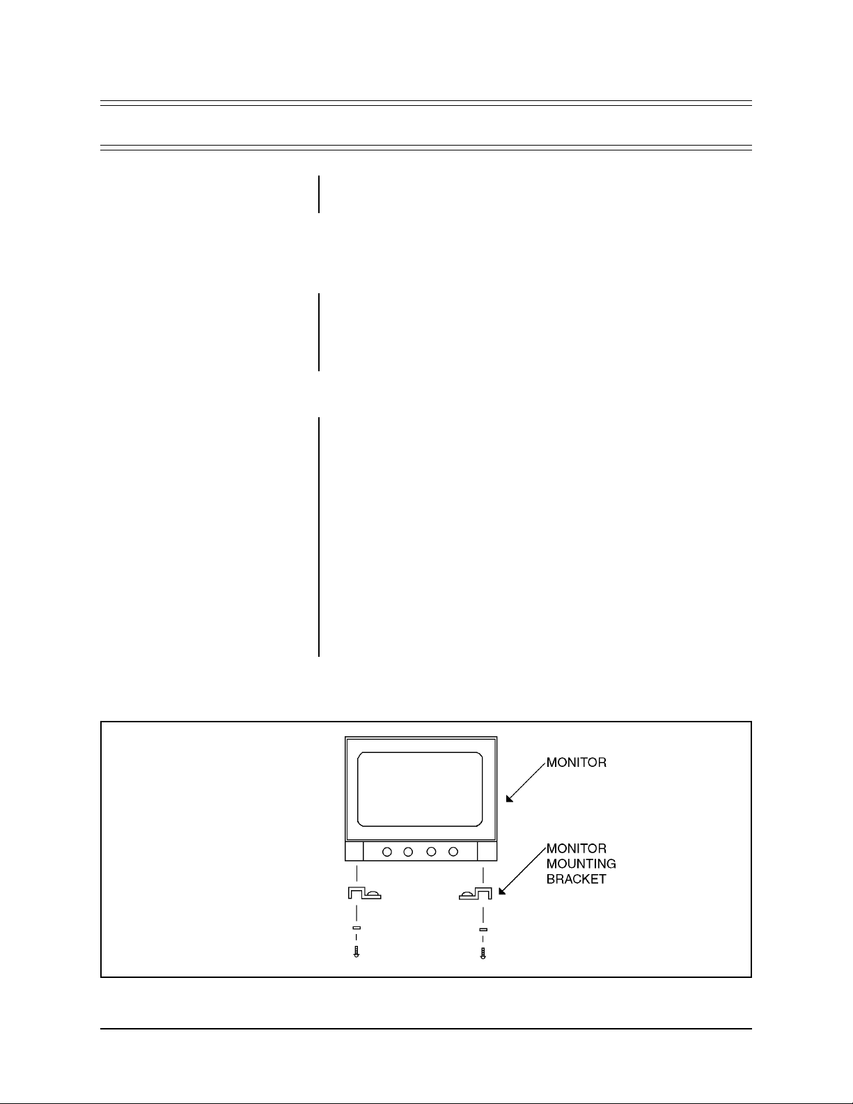
3.1.1 Monitor Assembly (See Figure 1)
1. Determine the location of the monitor mounting brackets. It will be most convenient to mount the brackets to the bottom of the monitor in place of the
rubber “feet”.
2. Remove the monitor rubber “feet” and install the monitor brackets in their place,
using the original hardware.
3.1.2 Hanger Assembly (See Figure 2)
1. Set the monitor assembly on the pan brackets (Item 1). This will help gauge
the rough positioning of the other brackets.
2. Fit together the top bracket (Item 3) and the two side arms (Item 4) and place
over the monitor assembly. Adjust each side arm equally outward to align the
fastener holes. Using the four (4) 1/4-20 x 5/8 hex bolts, flat washers,
lockwashers and hex nuts supplied, fasten the arms to the bracket.
3. Lift the top bracket assembly up until one of the holes in the side arms aligns
with the 1/2-13 threaded holes in the pan assemblies. Fasten the pan assemblies to the top bracket assembly with the two (2) 1/2-13 x 3/4 hex bolts supplied.
4. Remove the monitor assembly from the hanger assembly.
5. Thread the mounting pipe (Item 6) with the long-threaded section of pipe with
hole for cotter pin into the top bracket, insert cotter pin, and tighten the 8-32
screw in the pipe nut to lock the pipe threads.
Figure 1. Monitor Assembly
Pelco Manual C233M-G (8/95) 3
Page 8

3.1.3 Mounting the Hanger Assembly
NOTE:
When determining the
mounting location, consideration
must be given to the total weight of
the monitor and the mount. The
mounting surface must be adequate
to support this weight.
1. Determine the location for, and the type of mount to be used. Remember to
allow for adequate clearance on all sides of the monitor.
2. Use the adapter mount as a template to mark the required mounting holes.
3. Using the necessary fasteners, attach the adapter mount to the chosen surface.
4. Thread the mounting pipe into the mount, stopping at the desired position,
after the threads have become tight (approximately 30 ft lb). (If the MRCA or
MRWA is being used, tighten the 8-32 screw in the pipe nut to lock the pipe
threads.)
3.1.4 Monitor Mounting
1. Set the monitor assembly into the mounted hanger assembly.
2. Align the threaded inserts in the monitor brackets with the slots in the pan
bracket.
3. Secure the monitor assembly to the hanger assembly with the #10 screws,
lockwasher, and flat washers supplied. (See Figure 2)
4. Tilt the monitor to the desired angle and tighten the 1/2-13 hex bolts.
5. Make all necessary electrical connections.
4 Pelco Manual C233M-G (8/95)
Page 9

3.2 MRU ASSEMBLY INSTRUCTIONS
3.2.1 Hanger Assembly
1. Fit together the top bracket and the two side arms and place over the monitor/
receiver. Adjust each side arm equally outward to align the fastener holes.
Using the four (4) 1/4-20 x 5/8 hex bolts, flat washers, lock washers and hex
nuts supplied, fasten the arms to the top bracket.
2. Remove the monitor from the hanger assembly.
3. Thread the mounting pipe with the long-threaded section of pipe with hole for
cotter pin into the top bracket, insert cotter pin, and tighten the 8-32 screw in
the pipe nut to lock the pipe threads.
3.2.2 Mounting the Hanger Assembly
NOTE:
When determining the
mounting location, consideration
must be given to the total weight of
the monitor and the mount. The
mounting surface must be adequate
to support this weight.
1. Determine the location for, and the type of mount to be used. Remember to
allow for adequate clearance on all sides of the monitor.
2. Use the adapter mount as a template to mark the required mounting holes.
3. Using the necessary fasteners, attach the adapter mount to the chosen surface.
4. Thread the mounting pipe into the mount, stopping at the desired position,
after the threads have become tight, approximately 30 ft lb. (If the MRCA or
MRWA is being used, tighten the 8-32 screw in the pipe nut to lock the pipe
threads.)
3.2.3 Monitor Mounting
1. Align the holes in the side arms of the monitor bracket with the threaded holes
in the side of the monitor/receiver.
2. Attached the monitor/receiver to the mount with the supplied fasteners
3. Tilt the monitor to the desired angle and tighten the fasteners.
4. Make all necessary electrical connections.
Pelco Manual C233M-G (8/95) 5
Page 10

4.0 EXPLODED ASSEMBLY
An exploded assembly diagram for the MR4000 is shown in Figure 2. Items noted with an asterisk in the parts list (Table A) are parts
used for the MRU mount.
Figure 2. MR4000 Exploded Assembly
T able A. Mechanical Parts List: MR4000/MRU Universal Mounts
Item No. Qty Description Part Number
1 2 Bracket, Pan, Side MR40004100COMP
2 2 Bracket, Monitor MR40004001COMP
3 1 Bracket, Top, Horizontal* MRU1001WA
4 2 Arm, Top Side* MRU1000WA
5 — Not used
6 1 Pipe Mounting MRU* MRU4207COMP
7 2 Bolt, 1/2-13 x 3/4 Hex, SS* ZH1/213X.750CH
8 8 Nut, 1/4-20 Hex, SS* ZH1/4-20NUTCH
9 4 Bolt, 1/4-20 x 5/8 Hex C/S SS* ZH1/420X.625CH
10 — Not used
11 8 Washer, Split Lock 1/4 SS Medium* ZH1/4LWSSL
12 4 Screw, 10-32 x 1/2 Pan Phil, SS ZH10-32X.500SPP
13 4 Washer, Split Lock #10, SS Medium ZH10LWSSL
14 4 Washer, Flat #10, SS ZH204X436X60C
15 8 Washer, Flat 3/16* ZH260X562X65C
16 2 Washer, Flat 1/2 ZH515X875X62
*Denotes parts used for MRU mount.
6 Pelco Manual C233M-G (8/95)
Page 11

Construction: Steel
Finish: Polyester powder coat
Maximum Load: 150 lbs (68 kg)
Dimensions: See Figure 3
Weight: 20 lbs (9 kg)
Shipping Weight: 22 lbs (10 kg)
5.0 SPECIFICATIONS
MRWA
MR4000
MRCA
Figure 3. Dimension Drawings
Pelco Manual C233M-G (8/95) 7
Page 12

6.0 WARRANTY AND RETURN INFORMATION
WARRANTY
Pelco will repair or replace, without charge, any merchandise proved defective in
material or workmanship for a period of one (1) year after the date of shipment.
Exceptions to this warranty are as noted below:
• Two (2) years on all standard motorized and fixed focal length lenses.
• Two (2) years on Legacy®, Intercept®, CM8500/CM9500/CM9750 Matrix,
Spectra™, DF5 Series and DF8 Fixed Dome products.
• Two (2) years on WW5700 series window wiper (excluding wiper blades).
• Two (2) years on cameras.
• Six (6) months on all pan and tilts, scanners or preset lenses used in continuous motion applications (e.g., preset scan, tour and auto scan modes).
Pelco will warranty all replacement parts and repairs for 90 days from the date of
Pelco shipment. All goods requiring warranty repair shall be sent freight prepaid to
Pelco, Clovis, California. Repairs made necessary by reason of misuse, alteration,
normal wear, or accident are not covered under this warranty.
Pelco assumes no risk and shall be subject to no liability for damages or loss resulting from the specific use or application made of the Products. Pelco’s liability for
any claim, whether based on breach of contract, negligence, infringement of any
rights of any party or product liability, relating to the Products shall not exceed the
price paid by the Dealer to Pelco for such Products. In no event will Pelco be liable
for any special, incidental or consequential damages (including loss of use, loss of
profit and claims of third parties) however caused, whether by the negligence of
Pelco or otherwise.
®Pelco and the Pelco logo are
registered trademarks of Pelco.
©Copyright 1997, Pelco. All rights
reserved.
The above warranty provides the Dealer with specific legal rights. The Dealer may
also have additional rights, which are subject to variation from state to state.
If a warranty repair is required, the Dealer must contact Pelco at (800) 289-9100 or
(559) 292-1981 to obtain a Repair Authorization number (RA), and provide the
following information:
1. Model and serial number
2. Date of shipment, P .O. number , Sales Order number , or Pelco invoice number
3. Details of the defect or problem
If there is a dispute regarding the warranty of a product which does not fall under
the warranty conditions stated above, please include a written explanation with the
product when returned.
Ship freight prepaid to: Pelco
300 West Pontiac Way
Clovis, CA 93612-5699
Method of return shipment shall be the same or equal to the method by which the
item was received by Pelco.
RETURNS
In order to expedite parts returned to the factory for repair or credit, please call the
factory at (800) 289-9100 or (559) 292-1981 to obtain an authorization number (CA
number if returned for credit, and RA number if returned for repair). Goods returned
for repair or credit should be clearly identified with the assigned CA/RA number and
freight should be prepaid. All merchandise returned for credit may be subject to a
20% restocking and refurbishing charge.
Ship freight prepaid to: Pelco
300 West Pontiac Way
Clovis, CA 93612-5699
8 Pelco Manual C233M-G (8/95)
 Loading...