

Page 1
C236M-A (10/99)
MR4050
Monitor Mount
®
3500 Pelco Way,
Clovis, CA 93612-5699
USA
In North America & Canada:
Tel (800) 289-9100
FAX (800) 289-9150
International Customers:
Tel +1 (559) 292-1981
FAX +1 (559) 348-1120
www.pelco.com
WARNING:
Be sure
that you do not penetrate monitor circuit
boards or other electrical parts
when attaching the monitor adjustment brackets to the monitor.
If you do make contact with electrical parts, you may create an
electrical hazard and ground
power to the monitor mount.
DESCRIPTION
The MR4050 is a heavy-duty ceiling/wall monitor mount designed to support up to 150 pounds
(68 kg). It fits monitors from 19 to 31 inches (49 to 79 cm) wide.
INSTALLATION
Monitor Assembly
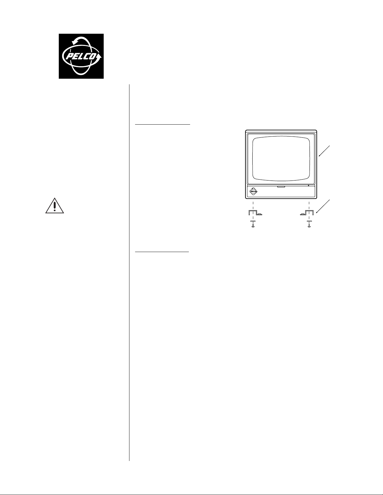
Refer to Figure 1.
Monitor With Removable Feet
Remove the rubber feet from the monitor and
install the monitor adjustment brackets in their
place, using the original hardware. The monitor
adjustment brackets are reversible, but both
brackets should be attached with the flat side
facing in or out.
Monitor Without Removable Feet
Decide where you will attach the monitor adjustment brackets. Attach the monitor adjustment brackets to your monitor using your own
mounting screws (not provided). The monitor
adjustment brackets are reversible, but both
brackets should be attached with the flat side
facing in or out.
Figure 1. Monitor Assembly
MONITOR
MONITOR
ADJUSTMENT
BRACKET
Hanger Assembly
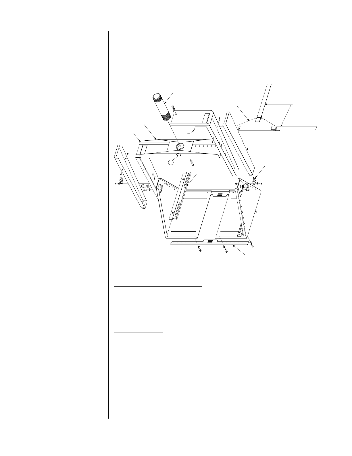
Refer to Figure 2.
1. Measure the height and width of the monitor. Place the pan end brackets on their sides with
the bottom ends facing you. Separate the pan end brackets the measured width of the
monitor.
2. Attach the L-brackets to the studs on the pan brackets with the four flat washers, lock washers, and 10-32 acorn nuts.
3. Place the monitor in the assembly to be sure the monitor fits correctly. Adjust the pan end
brackets if necessary .
4. Place the pan end bracket assembly on its side with the top end towards you.
5. Fit the top bar weld assembly and the two side arm top weld assemblies together.
6. Position the side arm top weld assemblies against the outside of the pan end brackets.
7. Fasten the side arms to the top bar by inserting four 1/4-20 x .625-inch bolts from the bottom of the top bar weld assembly. Attach flat washers, lock washers, and nuts inside the top
bar weld assembly and tighten.
8. Adjust each side arm equally, allo wing for the height of the monitor.
9. Align the top bracket assembly until one of the 1/2-inch bolt holes in the left side arm aligns
with a 1/2-inch hole in the left pan end bracket.
10. Fasten the left pan end bracket to the left, top bracket assembly with the 1/2-13 x 0.75-inch
bolt and washer and tighten. Repeat the procedure with the right side.
11. Adjust the mount to align the center angle adjustment hole in the left arm with the center
angle adjustment hole in the pan end bracket. Fasten a 1/4-20 x .625-inch bolt and washer.
Do not completely tighten. This bolt will be used later to lock the monitor at an angle. Repeat the procedure with the right side.
Page 2
12. Place the assembly upright on your work surface.
13. Thread the mounting pipe into the opening located in the middle of the top bar. Locate the
hole, see
Figure 2, in the side of the top bar weld assembly. Tighten the 8-32 Phillips
➀
screw, already located in the bar, to lock the mounting pipe into place.
14. Attach each side strap bracket to a pan end bracket with a 10-32 x .5-inch cap screw, lock
washer, washer, and acorn nut. Do not completely tighten. Repeat the procedure with the
right side.
MOUNTING PIPE
TOP BAR WELD
ASSEMBLY
SIDE ARM TOP
WELD ASSEMBLY
STRAP RETAINER BRACKET
1
MONITOR ADJUSTMENT
BRACKET
Figure 2. Hanger Assembly
L-BRACKET
SIDE COVER
SIDE STRAP
BRACKET
PAN END BRACKET
STRAPPING
Mounting the Hanger Assembly
1. Determine the mounting location. Install ceiling or wall mount by following the instructions
that are provided with the mount and then proceed to step 2. Make sure the mount can support four times its maximum specified load.
2. Thread the MR4050 mounting pipe into the ceiling or wall mount. Stop at the desired position after the threads have become tight (approximately 30 ft-lbs).
Monitor Mounting
1. Place the monitor in the mount.
2. Align the threaded inserts in the monitor adjustment brackets with the slots in the bottom of
the pan end brackets.
3. Secure the monitor to the pan end brackets with the four 10-32 x .5-inch socket head cap
screws, lock washers, and washers and tighten.
4. Be sure the .5-inch bolts holding the pan end brackets to the side arms
are firm enough so that the pan end bracket assembly will not tilt or fall
while the monitor angle is adjusted. To set the monitor angle remove the left 1/4-20
x .625-inch hex bolt and washer. Hold on to the monitor while removing the right 1/4-20 x
.625-inch hex bolt and washer. Tilt the monitor to the desired angle. Fasten the right pan
end bracket to the right side arm top weld assembly with the 1/4-20 x .625-inch hex bolt and
washer and tighten. Repeat with the left side.
Page 3

5. Firmly tighten the two 1/2-13 x 0.75-inch hex bolts on the pan end brackets.
6. Fit together the left side cover to the left side arm weld assembly. Fasten the side cover with
the 4-40 x .75-inch, Phillips screw. Repeat with the right side.
7. Loosely thread the 40-inch (101.6 cm) center strap through the back L-bracket. (Refer to
Figure 3, Illustration A, L-Bracket)
8. Loosely thread the left 28-inch (71.12 cm) side strap through the left side strap bracket.
Repeat with the right side. (Refer to Figure 3, Illustration B, Side Bracket)
9. Place the strap retainer bracket in the place that will best support the back of the monitor.
Adjust all straps to fit and tighten. Tighten the side strap brackets.
10. Make all necessary electrical connections.
A L-BRACKET
STRAP
B SIDE BRACKET
STRAP
ATTACHMENT OF THE CENTER STRAP
TO THE BOTTOM OF THE CENTER BRACE
(REAR VIEW)
FEED STRAP FROM SIDES OF TOP PLA TE
TO LEFT AND RIGHT CLAMPS AS SHOWN
(INSIDE VIEW)
Figure 3. Strap Attachments
MAINTENANCE
Regularly scheduled maintenance is not required. If you feel that the mount may experience excessive vibration, you can occasionally check the tightness of the nuts and bolts.
Service Manual
To order replacement parts for your unit, obtain a service manual in one of the following ways:
• Go to Pelco’s web site at ftp://www.pelco.com and find service manual C236SM.
• Contact Pelco’s Literature Department and request service manual C236SM.
SPECIFICATIONS
Tilt Angle: Adjustable increments of ±20° or ±40°
Maximum Load: 150 lb (68 kg)
Construction: Steel
Finish: Black polyester powder coat
Environment: Indoor only
Dimensions
Fits Monitors
Minimum: 19 (W) x 21 (H) x 14 (D) inches (49 x 53 x 36 cm)
Maximum: 31 (W) x 30 (H) x 14 (D) inches (79.5 x 76 x 36 cm)
Weight: 27 lb (12.43 kg)
(Design and product specifications subject to change without notice.)
Page 4

WARRANTY AND RETURN INFORMATION
WARRANTY
Pelco will repair or replace, without charge, any merchandise proved defective in material
or workmanship for a period of one year after the date of shipment.
Exceptions to this warranty are as noted below:
• Five years on FT/FR8000 Series fiber optic products.
• Three years on Genex® Series products (multiplexers, server, and keyboard).
• Three years on Camclosure® and fixed camera models, except the CC3701H-2,
CC3701H-2X, CC3751H-2, CC3651H-2X, MC3651H-2, and MC3651H-2X camera
models, which have a five-year warranty.
• Two years on standard motorized or fixed focal length lenses.
• Two years on Legacy®, CM6700/CM6800/CM9700 Series matrix, and DF5/DF8 Series
fixed dome products.
• Two years on Spectra®, Esprit®, ExSite™, and PS20 scanners, including when used in
continuous motion applications.
• Two years on Esprit® and WW5700 Series window wiper (excluding wiper blades).
• Eighteen months on DX Series digital video recorders, NVR300 Series network video
recorders, and Endura™ Series distributed network-based video products.months on DX
Series digital video recorders, NVR300 Series network video recorders, Endura™ Series
distributed network-based video products, and TW3000 Series twisted pair transmission
products.
• One year (except video heads) on video cassette recorders (VCRs). Video heads will be
covered for a period of six months.
• Six months on all pan and tilts, scanners or preset lenses used in continuous motion
applications (that is, preset scan, tour and auto scan modes).
Pelco will warrant all replacement parts and repairs for 90 days from the date of Pelco
shipment. All goods requiring warranty repair shall be sent freight prepaid to Pelco, Clovis,
California. Repairs made necessary by reason of misuse, alteration, normal wear, or
accident are not covered under this warranty.
Pelco assumes no risk and shall be subject to no liability for damages or loss resulting
from the specific use or application made of the Products. Pelco’s liability for any claim,
whether based on breach of contract, negligence, infringement of any rights of any party
or product liability, relating to the Products shall not exceed the price paid by the Dealer to
Pelco for such Products. In no event will Pelco be liable for any special, incidental or
consequential damages (including loss of use, loss of profit and claims of third parties)
however caused, whether by the negligence of Pelco or otherwise.
The above warranty provides the Dealer with specific legal rights. The Dealer may also
have additional rights, which are subject to variation from state to state.
If a warranty repair is required, the Dealer must contact Pelco at (800)289-9100 or
(559) 292-1981 to obtain a Repair Authorization number (RA), and provide the following
information:
1. Model and serial number
2. Date of shipment, P.O. number, Sales Order number, or Pelco invoice number
3. Details of the defect or problem
If there is a dispute regarding the warranty of a product which does not fall under the
warranty conditions stated above, please include a written explanation with the product
when returned.
Method of return shipment shall be the same or equal to the method by which the item
was received by Pelco.
RETURNS
In order to expedite parts returned to the factory for repair or credit, please call the factory
at (800) 289-9100 or (559) 292-1981 to obtain an authorization number (CA number if
returned for credit, and RA number if returned for repair).
All merchandise returned for credit may be subject to a 20% restocking and refurbishing
charge.
Goods returned for repair or credit should be clearly identified with the assigned CA or RA
number and freight should be prepaid. Ship to the appropriate address below.
If you are located within the continental U.S., Alaska, Hawaii or Puerto Rico, send goods
to:
If you are located outside the continental U.S., Alaska, Hawaii or Puerto Rico and are
instructed to return goods to the USA, you may do one of the following:
If the goods are to be sent by a COURIER SERVICE, send the goods to:
If the goods are to be sent by a FREIGHT FORWARDER, send the goods to:
Service Department
Pelco
3500 Pelco Way
Clovis, CA 93612-5699
Pelco
3500 Pelco Way
Clovis, CA 93612-5699 USA
Pelco c/o Expeditors
473 Eccles Avenue
South San Francisco, CA 94080 USA
Phone: 650-737-1700
Fax: 650-737-0933
REVISION HISTORY
Manual # Date Comments
C236M 12/97 Original version. Improved, more aesthetic, stronger version of the MR4000 mount per ECR #97-479.
C236M-A 10/99 Rev. A. Revised to new format. Moved exploded assembly diagram and parts list to new maintenance/service manual
(C236SM).
® Pelco, the Pelco logo, Spectra, Esprit, Genex, Legacy, and Camclosure are registered trademarks of Pelco.
™ Endura and ExSite are trademarks of Pelco. © Copyright 1999, Pelco. All rights reserved.
 Loading...