

Page 1
ON
PAN
TILT
AUTO
PAN
SPEED
SPEED
UP
OFF
MPTV1510PAZ
MANUAL
ZOOM
FOCUS
IRIS
TELE
LEFT
NEAR
OPEN
RIGHT
DOWN
SPEED
WIDE
FAR
CLOSE
MPT1510DT and
MPTV1510 Series
Controllers
Installation/
Operation Manual
C565M-B (7/98)
Pelco • 3500 Pelco Way, Clovis • CA 93612-5699 USA • www.pelco.com
In North America and Canada: Tel (800) 289-9100 or FAX (800) 289-9150
International Customers: Tel (1-559) 292-1981 or FAX (1-559) 348-1120
Page 2

CONTENTS
Section Page
1.0 GENERAL .................................................................................................. 3
1.1 IMPORTANT SAFEGUARDS AND WARNINGS ...............................3
1.2 UNPACKING INSTRUCTIONS .......................................................... 4
1.3 RECOMMENDED TOOLS .................................................................4
2.0 DESCRIPTION .......................................................................................... 5
2.1 MODELS ............................................................................................ 5
3.0 INSTALLATION ..........................................................................................6
3.1 OUTPUT CONNECTOR ASSEMBLY ................................................6
3.2 SYSTEM CONNECTIONS ................................................................ 6
4.0 OPERATION ..............................................................................................8
5.0 TROUBLESHOOTING ...............................................................................9
6.0 SPECIFICATIONS ....................................................................................10
7.0 WARRANTY AND RETURN INFORMATION ........................................... 12
LIST OF ILLUSTRATIONS
Figure Page
1 Output Connector Assembly Diagram ............................................... 7
2 Model MPTV1510PAZ Front Panel.................................................... 8
LIST OF TABLES
Table Page
A Output Connector Pin Assignments ...................................................7
REVISION HISTORY
Manual # Date Comments
C565M 1/85 Original version (schematics only).
C565M-A 6/90 Added text.
C565M-B 7/98 Reformatted and added Model MPTV1510PZ.
Removed schematics.
2 Pelco Manual C565M-B (7/98)
Page 3
1.0 GENERAL
1.1 IMPORTANT SAFEGUARDS AND WARNINGS
Prior to installation and use of this product, the following WARNINGS should be
observed.
1. Installation and servicing should only be done by qualified service personnel
and conform to all local codes.
2. Only use replacement parts recommended by Pelco.
3. After replacement/repair of this unit’s electrical components, conduct a
resistance measurement between line and exposed parts to verify the
exposed parts have not been connected to line circuitry.
The product and/or manual may bear the following marks:
This symbol indicates that dangerous voltage constituting a
risk of electric shock is present within this unit.
This symbol indicates that there are important operating and
maintenance instructions in the literature accompanying this
unit.
CAUTION:
RISK OF
ELECTRIC SHOCK.
DO NOT OPEN.
TO REDUCE THE RISK OF ELECTRICAL SHOCK,
DO NOT REMOVE COVER. NO USER-
SERVICEABLE PARTS INSIDE. REFER SERVICING
TO QUALIFIED SERVICE PERSONNEL.
CAUTION:
Please thoroughly familiarize yourself with the information
in this manual prior to installation and operation.
Pelco Manual C565M-B (7/98) 3
Page 4

1.2 UNPACKING INSTRUCTIONS
Unpack and inspect all parts carefully.
The following items are supplied:
1 MPT1510DT or MPTV1510 Series Controller
1 Installation/Operation Manual (C565M-B)
Be sure to save the shipping carton, boxes and inserts. They are the safest materials in which to make future shipments.
If an item appears to have been damaged in shipment, replace it properly in its box
and contact the factory at 1-800-289-9100 or 1-559-292-1981 for a replacement.
(International customers fax 1-559-348-1120 for authorization and instructions.)
If an item needs to be returned to the factory for repair, consult the WARRANTY
AND RETURN section of this manual for instructions.
1.3 RECOMMENDED TOOLS
Pelco does not supply the basic tools needed for the installation process. The following tools are recommended.
Wire stripper
AMP style crimp tool
4 Pelco Manual C565M-B (7/98)
Page 5

The MPT1510DT or MPTV1510 Series Controllers provide all the necessary electronics to implement the features below for Pelco's PT1250DC heavy duty and
PT550P medium duty 115 VDC pan and tilt units.
• Pan and tilt control via a joystick
• Pan and tilt speed control (on some models)
• Auto scan (on some models)
• Zoom lens control (on some models)
• Desk top or rack mount options, depending on the model
The front panels on all models contain a power switch, pilot lamp, and a joystick.
The controls for the remaining features listed above are also located on the front
panel, depending upon the model. The rear panel provides the 120 VAC, 60 Hz
power cord and a 14-pin Amp hard-wired connector to interface with the pan and tilt
unit.
2.1 MODELS
MPT1510DT Desktop joystick control for 115 VDC pan and tilt units
MPTV1510DT Same as MPT1510DT except variable speed
2.0 DESCRIPTION
MPTV1510CAZ Same as MPTV1510DT except auto scan and zoom lens
MPTV1510PZ Rack mount joystick with variable speed and zoom lens control
MPTV1510PAZ Same as MPTV1510PZ except auto scan control
control
for 115 VDC pan and tilt units
Pelco Manual C565M-B (7/98) 5
Page 6

3.0 INSTALLATION
3.1 OUTPUT CONNECTOR ASSEMBLY
Assemble the connector parts according to the instructions below. Refer to Figure 1
during assembly. For best results use an AMP style crimper when making the wireto-pin connection.
1. Slide the connector clamp assembly over the conductor cable. If the diameter
of the conductor cable is such that the rubber boot will slide over it easily then
slide the rubber boot onto the conductor cable at this time. If not, discard the
rubber boot.
2. Prepare the wires from the conductor cable as follows. Refer to Detail A in
Figure 1.
a. Strip at least 1" from the cable jacket to expose the wires. You may need
to strip more from the cable jacket if you have more wires.
b. Strip 1/8" from each wire.
c. Using an AMP style crimper, crimp the wires and their insulation to the
connector pins.
3. Slide the connector pins into the appropriate holes in the connector body until
they snap into place. Refer to Table A for output connector pin assignments,
depending on model and options. Refer to Detail B in Figure 1 for the pin
arrangement.
4. Push the connector clamp assembly (with boot, if used) toward the connector
body. Screw the clamp assembly onto the connector body, being careful not to
disturb the wires.
5. To complete the assembly, attach the appropriate clamp with the screws provided and tighten.
3.2 SYSTEM CONNECTIONS
1. For the rack mount models, install the controller in an appropriate rack.
2. Connect the output cable to the pan and tilt unit and to the rear panel (OUT 1)
of the controller.
3. Connect the 120 VAC, 60 Hz power cord, on the rear panel, to a power receptacle. Some models have an auxiliary AC OUTLET installed on the rear panel
for user convenience.
6 Pelco Manual C565M-B (7/98)
Page 7

13
47
8
1214
OR
1"
1/8"
Figure 1. Output Connector Assembly Diagram
Table A. Output Connector Pin Assignments
Pin No. Function
1 Pan/tilt common
2 No connection
3 Pan left
4 Field supply
5 Tilt down
6 Tilt up
7 Pan right
8 Ground
9 No connection
10 Iris
11 Focus
12 Zoom
13 Lens common
14 No connection
FRONT VIEW
14-PIN
11
Pelco Manual C565M-B (7/98) 7
Page 8
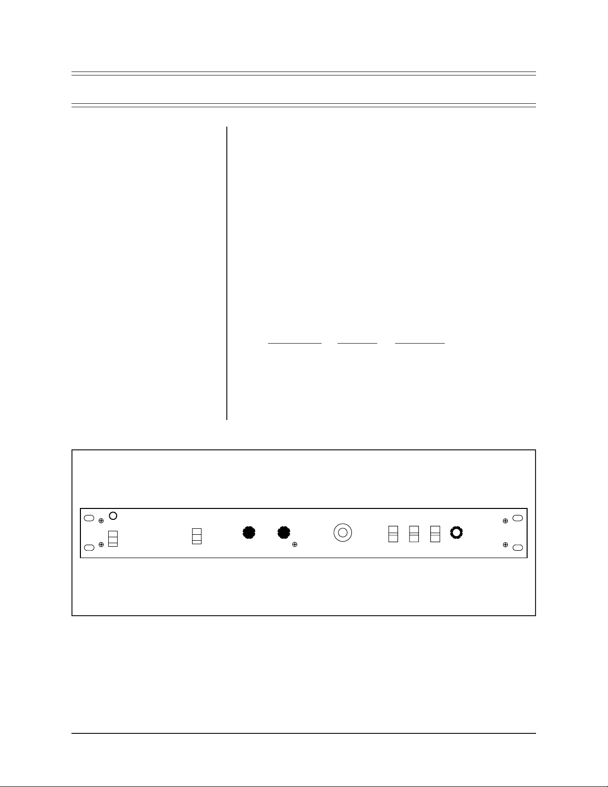
4.0 OPERATION
Refer to Figure 2.
1. Set the power switch to the ON position to activate the controller. The pilot
lamp will light when power is applied.
2. If your model has a PAN switch, set it in either the AUTO position to select
auto scan (pan) or the MANUAL position to use the joystick.
3. Operate the pan function by moving the joystick LEFT or RIGHT.
4. Operate the tilt function by moving the joystick UP or DOWN.
5. Adjust the TILT SPEED or PAN SPEED by rotating the respective knobs (on
some models). The clockwise direction increases speed and counterclockwise decreases speed. The PAN SPEED control can be used with the PAN
switch in either position.
6. On some models, the camera lens can be operated by three switches and one
lens speed control. The lens must have motorized zoom, focus, and iris capabilities in order for these lens control functions to operate. The switches are
spring-loaded to the center or off position and control the following:
Switch function Up position Down position
ZOOM TELE WIDE
FOCUS NEAR FAR
IRIS OPEN CLOSE
ON
OFF
MPTV1510PAZ
PAN
AUTO
MANUAL
The lens SPEED control will adjust the speed of all lens functions simultaneously, not individually. Rotating the knob in the clockwise direction increases
speed and counterclockwise decreases speed.
TILT
SPEED
PAN
SPEED
LEFT
UP
RIGHT
DOWN
ZOOM
TELE
WIDE
Figure 2. Model MPTV1510PAZ Front Panel
FOCUS
NEAR
FAR
IRIS
OPEN
CLOSE
SPEED
8 Pelco Manual C565M-B (7/98)
Page 9

5.0 TROUBLESHOOTING
If operating problems are experienced with the controller, check the fuses and the
power supply cord. Next, check the condition of the output cable and its two connections.
There is nothing else that can be done without the aid of proper test equipment. It is
recommended that your dealer or the Pelco Customer Service Department be contacted for assistance. Refer to Section 7.0 for warranty and return information.
Pelco Manual C565M-B (7/98) 9
Page 10

6.0 SPECIFICATIONS
ELECTRICAL
Input Voltage: 120 VAC, 50/60 Hz
Maximum Power
Requirements: 250 vA
Power Cord: 3-wire grounded, #18 AWG
Fuse Protection:
Model F1 F2 F3
MPT1510DT 1 A N/A N/A
MPTV1510DT 2 A N/A N/A
MPTV1510CAZ 3 A 2 A 0.2 A Slow Blow
MPTV1510PZ 3 A 2 A 0.2 A Slow Blow
MPTV1510PAZ 3 A 2 A 0.2 A Slow Blow
NOTE:
Values in parentheses are
centimeters; all others are inches.
Receptacles: 14-pin AMP CPC type
Auxiliary convenience outlet (on some models)
GENERAL
Construction
Cover: Steel, baked enamel finish (black leatherette)
Chassis: Steel, zinc plated
Panel: Aluminum, baked enamel finish (black with white silkscreen)
DIMENSIONS
Height Width Depth
MPT1510DT 1.8 (4.6) 5.5 (14.0) 8.9 (22.6)
MPTV1510DT 1.8 (4.6) 5.5 (14.0) 8.9 (22.6)
MPTV1510CAZ 1.8 (4.6) 19.0 (48.3) 10.2 (25.9)
MPTV1510PZ 1.8 (4.6) 19.0 (48.3) 10.2 (25.9)
MPTV1510PAZ 1.8 (4.6) 19.0 (48.3) 10.2 (25.9)
(Design and product specifications subject to change without notice.)
10 Pelco Manual C565M-B (7/98)
Page 11

NOTES
Pelco Manual C565M-B (7/98) 11
Page 12

7.0 WARRANTY AND RETURN INFORMATION
WARRANTY
Pelco will repair or replace, without charge, any merchandise proved defective in material or
workmanship for a period of one year after the date of shipment.
Exceptions to this warranty are as noted below:
Pelco, the Pelco logo, Camclosure, Esprit,
Genex, Legacy, and Spectra are registered
trademarks of Pelco.
Endura and ExSite are trademarks of Pelco.
© Copyright 1998, Pelco. All rights reserved.
• Five years on FT/FR8000 Series fiber optic products.
• Three years on Genex
• Three years on Camclosure
CC3751H-2, CC3651H-2X, MC3651H-2, and MC3651H-2X camera models, which have a fiveyear warranty.
• Two years on standard motorized or fixed focal length lenses.
• Two years on Legacy
dome products.
• Two years on Spectra
continuous motion applications.
• Two years on Esprit
• Eighteen months on DX Series digital video recorders, NVR300 Series network video
recorders, and Endura
• One year (except video heads) on video cassette recorders (VCRs). Video heads will be
covered for a period of six months.
• Six months on all pan and tilts, scanners or preset lenses used in continuous motion applications
(that is, preset scan, tour and auto scan modes).
Pelco will warrant all replacement parts and repairs for 90 days from the date of Pelco shipment.
All goods requiring warranty repair shall be sent freight prepaid to Pelco, Clovis, California. Repairs
made necessary by reason of misuse, alteration, normal wear, or accident are not covered under
this warranty.
Pelco assumes no risk and shall be subject to no liability for damages or loss resulting from the
specific use or application made of the Products. Pelco’s liability for any claim, whether based on
breach of contract, negligence, infringement of any rights of any party or product liability, relating
to the Products shall not exceed the price paid by the Dealer to Pelco for such Products. In no event
will Pelco be liable for any special, incidental or consequential damages (including loss of use, loss
of profit and claims of third parties) however caused, whether by the negligence of Pelco or
otherwise.
The above warranty provides the Dealer with specific legal rights. The Dealer may also have
additional rights, which are subject to variation from state to state.
If a warranty repair is required, the Dealer must contact Pelco at (800) 289-9100 or (559) 292-1981
to obtain a Repair Authorization number (RA), and provide the following information:
1. Model and serial number
2. Date of shipment, P.O. number, Sales Order number, or Pelco invoice number
3. Details of the defect or problem
If there is a dispute regarding the warranty of a product which does not fall under the warranty
conditions stated above, please include a written explanation with the product when returned.
Method of return shipment shall be the same or equal to the method by which the item was received
by Pelco.
RETURNS
In order to expedite parts returned to the factory for repair or credit, please call the factory at (800)
289-9100 or (559) 292-1981 to obtain an authorization number (CA number if returned for credit,
and RA number if returned for repair).
All merchandise returned for credit may be subject to a 20% restocking and refurbishing charge.
Goods returned for repair or credit should be clearly identified with the assigned CA or RA number
and freight should be prepaid. Ship to the appropriate address below.
If you are located within the continental U.S., Alaska, Hawaii or Puerto Rico, send goods to:
Service Department
Pelco
3500 Pelco Way
If you are located outside the continental U.S., Alaska, Hawaii or Puerto Rico and are instructed
to return goods to the USA, you may do one of the following:
Clovis, CA 93612-5699
If the goods are to be sent by a COURIER SERVICE, send the goods to:
Pelco
3500 Pelco Way
Clovis, CA 93612-5699 USA
If the goods are to be sent by a FREIGHT FORWARDER, send the goods to:
Pelco c/o Expeditors
473 Eccles Avenue
South San Francisco, CA 94080 USA
Phone: 650-737-1700
Fax: 650-737-0933
®
Series products (multiplexers, server, and keyboard).
®
and fixed camera models, except the CC3701H-2, CC3701H-2X,
®
, CM6700/CM6800/CM9700 Series matrix, and DF5/DF8 Series fixed
®
, Esprit®, ExSite™, and PS20 scanners, including when used in
®
and WW5700 Series window wiper (excluding wiper blades).
™
Series distributed network-based video products.
This equipment contains electrical or electronic components that must be recycled properly to comply with Directive 2002/96/EC of the European Union
regarding the disposal of waste electrical and electronic equipment (WEEE). Contact your local dealer for procedures for recycling this equipment.
12 Pelco Manual C565M-B (7/98)
 Loading...