

®
MPT9000CZ/
MPT9000PZ
Transmitter/
Control
(Coaxitron
®
System 2000)
Installation/
Operation Manual
C550M-E (8/97)
Pelco • 3500 Pelco Way, Clovis, CA 93612-5699 • USA • www.pelco.com
In North America and Canada: Tel (800) 289-9100 • FAX (800) 289-9150
International Customers: Tel (1-559) 292-1981 or FAX (1-559) 348-1120

TABLE OF CONTENTS
Section Page
1.0 WARNING ..........................................................................................................................................1
2.0 SCOPE ...............................................................................................................................................2
3.0 DESCRIPTION ...................................................................................................................................2
4.0 INSTALLATION ..................................................................................................................................2
4.1 RECEIVER POWER INPUT MODIFICATIONS ....................................................................... 2
4.1.1 24 VAC Input Conversion ............................................................................................ 2
4.2 CONNECTOR ASSEMBLY ......................................................................................................5
4.3 SYSTEM CONFIGURATIONS ................................................................................................. 7
5.0 OPERATIONS ..................................................................................................................................10
5.1 FUNCTIONAL CIRCUIT DESCRIPTION................................................................................ 10
5.2 TRANSMITTER ......................................................................................................................11
5.2.1 Controls .....................................................................................................................11
5.3 RECEIVER ............................................................................................................................. 11
5.4 RECEIVER/TRANSMITTER INPUTS AND OUTPUTS ..........................................................11
5.5 COAXITRON PREPOSITION RECEIVER ............................................................................. 12
5.5.1 Power-Up Routine .....................................................................................................13
5.5.2 Creating Presets ........................................................................................................13
5.6 AUXILIARY FUNCTIONS .......................................................................................................17
5.7 AUTO/RANDOM OPERATION............................................................................................... 21
5.8 CX900TLC MANUAL/TEST MODULE ................................................................................... 21
6.0 TROUBLESHOOTING GUIDELINES ..............................................................................................23
7.0 MAINTENANCE ............................................................................................................................... 23
8.0 MODEL NUMBERS ..........................................................................................................................24
8.1 OPTIONAL ACCESSORIES ..................................................................................................25
8.2 RECOMMENDED CABLES.................................................................................................... 25
9.0 SPECIFICATIONS ...........................................................................................................................25
10.0 WARRANTY AND RETURN INFORMATION ..................................................................................28
Pelco, the Pelco Logo, Camclosure, Coaxitron, Esprit, Genex, Legacy, and Spectra are registered trademarks of Pelco. © Copyright 1997, Pelco. All rights reserved.
Endura and ExSite are trademarks of Pelco.
ii Pelco Manual C550M-E (8/97)

LIST OF ILLUSTRATIONS
Figure Page
1 Coaxitron System 2000 Receiver ................................................................................................... 3
2 24 VAC Input Wiring Schematic ..................................................................................................... 3
3 AC Input and Fuse Values ............................................................................................................. 4
4 Connector Assembly ......................................................................................................................5
5 Receiver Control Output/Input Pin Assignments ............................................................................ 6
6 Basic Coaxitron System 2000 ........................................................................................................7
7 Coaxitron System 2000 with Manual Video Switcher and Multiple Cameras ................................. 7
8 Coaxitron System 2000 with Multiple Transmitters ........................................................................ 8
9 Coaxitron System 2000 with Multiple Transmitters and Receivers ................................................ 9
10 Coaxitron System 2000 Basic Interconnect Diagram ..................................................................... 9
11 Wiring Diagram for preposition Alarm Outputs ............................................................................. 13
12 SB1900, SS2000, SB2500 and SB2600 Series Preset Wiring Diagram ...................................... 14
13 PT280, PT520, PT550, PT570, PT680, PT1250,PT1280 and SB2800 Series Preset Wiring
Diagram ........................................................................................................................................ 15
14 Lens Preset Wiring Diagram ........................................................................................................ 16
15 Jumper Settings, Receiver/Driver Mother Board .......................................................................... 17
16 External Device Wiring Diagram .................................................................................................. 18
17 Auxiliary Functions Wiring Diagram ............................................................................................. 19
18 AI700/AI701 Wiring Diagram ........................................................................................................ 20
19 Coaxitron Receiver Assembly Layout (Top View) ........................................................................ 21
20 A9000 Wiring Schematic .............................................................................................................. 22
21 CX900TLC Test Module and Wiring Schematic ........................................................................... 23
Pelco Manual C550M-E (8/97) iii

REVISION HISTORY
Manual # Date Comments
C550M — Original version.
C550M 8/89 Rev. A. Manual revised to new format.
C550M 9/90 Rev. B. Manual revised to include 230 VAC, 12 V and
preset (PP) models. Sections 2.1-2.3, 4.1.1, 4.2 and 5.5-
5.6 revised.
C550M 5/91 Rev. C. New figure added for connector assembly (Fig.
2); Figure 16 revised.
C550M 6/92 Rev. D. Revised to 2-column format. Section 4.1.1 and
Figures 10-12 revised.
ADDENDUM to Rev. D created 6/93 for CX9024RX field
modification procedures. Pages 4, 18 and 19 revised;
pages 4-1 and 19-1 added. (Addendum was incorporated in reprint of manual as pages 4, 5, 5-1, 5-2, 18, 19,
19-1 and 19-2.)
C550M-E 11/94 Rev. E. Completely revised. Updated for PCB1500529
REV J and PCB1500529 REV K production models.
Incorporates update for fuse values per ECO 94-376.
8/96 Revised fusing values for fuse #F1, Figure 3.
10/96 Revised Figure 2, 24 VAC Input Wiring Schematic, per
ECO #96-278.
8/97 Revised fusing values for fuse #F2, Figure 3 per ECO#
96-362.
iv Pelco Manual C550M-E (8/97)
INSTALLATION/OPERATION MANUAL
COAXITRON SYSTEM 2000
1.0 WARNINGS
Prior to installation and use of this product, the following
WARNINGS should be observed.
1. Installation and servicing should only be done by
Qualified Service Personnel and conform to all
Local codes.
2. Unless the unit is specifically marked as a NEMA
Type 3-6P enclosure, it is designed for Indoor use
only and it must not be installed where exposed to
rain and moisture.
3. The product bears the following marks:
This symbol indicates that dangerous voltage
constituting a risk of electric shock is present
within this unit.
CAUTION:
TO REDUCE THE RISK OF ELECTRICAL
SHOCK, DO NOT REMOVE COVER. NO
USER-SERVICEABLE PARTS INSIDE.
REFER SERVICING TO QUALIFIED
SERVICE PERSONNEL.
4. Only use replacement parts recommended by Pelco.
5. After replacement/repair of this unit’s electrical
components, conduct a resistance measurement
between line and exposed parts to verify the exposed
parts have not been connected to line circuitry.
This symbol indicates that there are important
operating and maintenance instructions in the
literature accompanying this unit.
CAUTION:
RISK OF ELECTRIC SHOCK.
DO NOT OPEN.
Please thoroughly familiarize yourself with the information in this manual
prior to installation and operation.
Pelco Manual C550M-E (8/97) 1

NOTE: This manual applies to those Coaxitron
systems using either PCB1500529 REV J or
PCB1500529 REV K boards. PCB board drawings were done from the REV J board perspective;
however, differences between the two boards that
affect function or operation are clearly pointed out.
2.0 SCOPE
Coaxitron System 2000 is an improved version of the
original Coaxitron. Improvements include the following features:
1. When used with an AI700 Auto Iris Servo, three
latching functions rather than two are available: (a)
auto scan, (b) camera power and (c) auto/manual
iris.
The information contained within this manual covers
the installation and operation of the Coaxitron System
2000 (transmitter control and receiver).
Installation should be in accordance with all applicable
local and national electric codes, utilizing approved
materials only.
Please thoroughly familiarize yourself with the information in this manual prior to installation and operation.
3.0 DESCRIPTION
The Coaxitron System 2000 control system provides up
to 16 remote control functions without the need for
control cables other than for a dedicated video cable for
the normal transmission of a remote camera signal to the
local monitoring and control position. The Coaxitron
Control System lends itself to application in situations
where short-to-medium distances are involved and where
equalization of cable losses is not required.
Typically, these functions are:
1. Pan Left 9. Iris Open
2. Pan Right 10. Iris Close
3. Tilt Up 11. Camera Power On/Off
4. Tilt Down 12. Auto/Manual Scan
5. Zoom In 13. AUX 1 (Manual Iris)
6. Zoom Out 14. AUX 2 (Auto Iris)
7. Focus Near 15. AUX 3
8. Focus Far 16. AUX 4
Functions 1 through 10, 15 and 16 are momentary; that
is , they are only actuated while the associated control
switch located on the Coaxitron transmitter or front
panel is operated. Functions 11, 12, 13 and 14 are
latching; that is, camera power, auto scan, and auto/
manual iris are latching functions and remain on until
turned off. The latching iris function is not dedicated,
and with proper interfacing, it can be used for some
other latching function. Alternately, AUX 1, 2, 3 and 4
may be used as momentary functions to control such
things as lights or gates with proper external interfacing.
Up to ten functions can be operated simultaneously.
Functions 11 through 16 must be used individually;
although any one of these functions may be used simultaneously with functions 1 through 10.
2. When used with a CX900TLC Local Test Board
Plug-in Module, manual control of functions from
the receiver location plus the ability to check for the
valid reception of a given command from the
transmitter.
3. Pan/tilt, zoom lens and camera power control are
included on the main (video and logic) receiver
board, which eliminates malfunctions due to
miswiring or broken wires.
Coaxitron System 2000 provides the following standard functions on a single circuit board and chassis with
integral power supply:
1. Pan/Tilt (24 VAC or 120 VAC as ordered from the
factory)
2. Zoom Lens — Zoom, iris, and focus with adjustable speed (speed not remote controllable)
3. Camera power (24 VAC or 120 VAC as ordered
from the factory)
4. An open collector transistor output (latching) intended for use in manual override of an automatic
iris control.
4.0 INSTALLATION
Coaxitron System 2000 installation includes the connection of all coaxial cable to the proper connectors,
depending on your system configuration. Various connector assembly pin-out geometries are shown in Figure
4. Connector location and pin assignments are illus-
trated in Figure 5.
For optional auxiliary functions, consult the factory to
make the proper connections between the receiver, pan/
tilt and camera/enclosure.
4.1 RECEIVER POWER INPUT
MODIFICATIONS
4.1.1 24 VAC Input Conversion
The CX9024RX series receivers can be converted to
operate with a 24 VAC input. If desired (see Figure 2).
Please contact factory for more information. For AC
input and fuse values, refered to Figure 3.
2 Pelco Manual C550M-E (8/97)
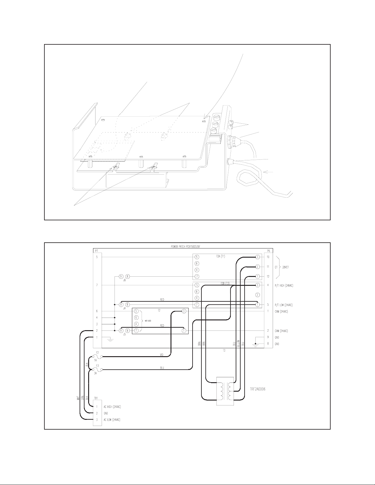
T1
T2
T3
Remove or loosen the four patch panel mounting
screws indicated below to gain access to patch
panels T1, T2, and T3.
SCREWS
PC BOARD
Remove PC board mounting screws
and remove the PC board.
If necessary, tag and remove
any affected cables attached to
the PC board.
BNC
CONNECTORS
37-PIN
AMP CONNECTOR
POWER INPUT
REMOVE POWER
CORD
SCREWS
COAXITRON SYSTEM 2000
RECEIVER
Figure 1. Coaxitron System 2000 Receiver
COAXITRON II POWER PATCH
(24 VAC INPUT/24 VAC OUT)
Figure 2. 24 VAC Input Wiring Schematic
Pelco Manual C550M-E (8/97) 3
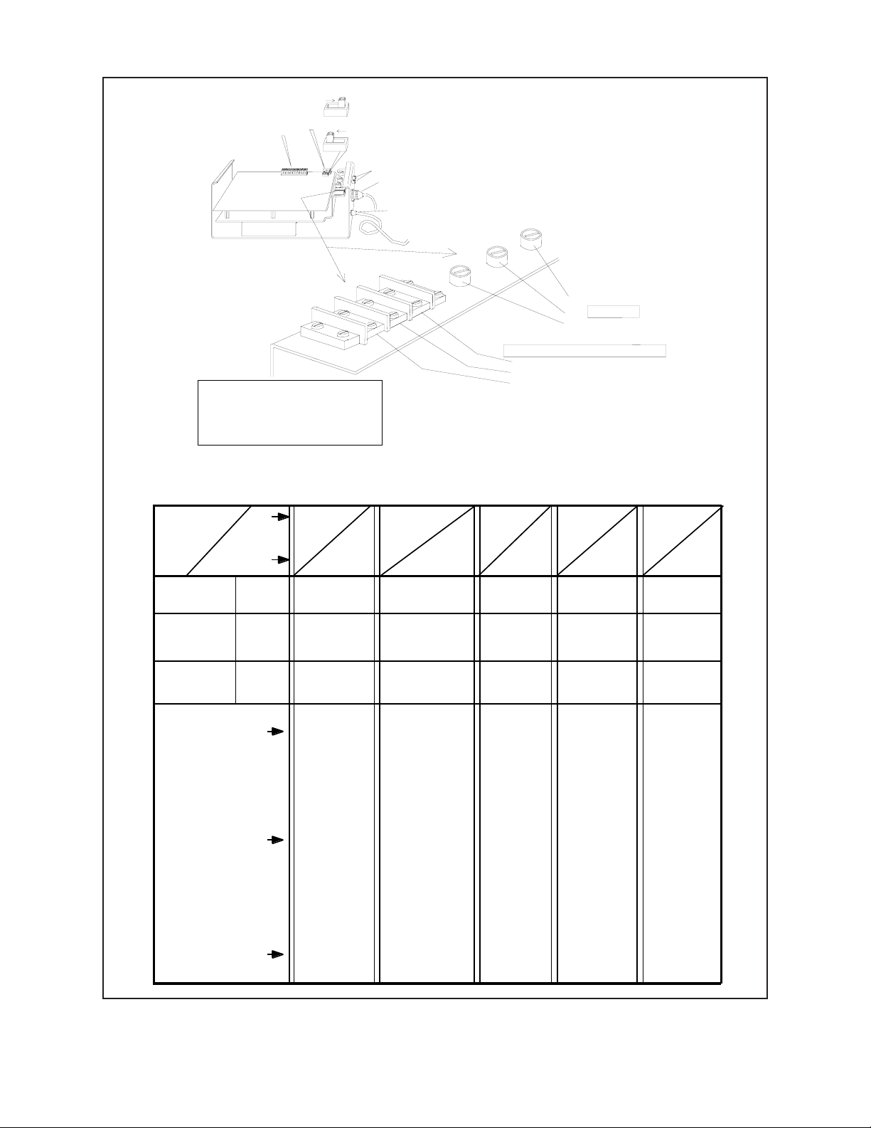
SW 1
P2
P1
PC BOARD
**
For REV K boards, the SW1
switch positions shown above
are just reversed; i.e., "Short"
is "Long" and "Long" is "Short".
SW 1
shown in the
"Long" position
shown in the
"Short" position
BNC
CONNECTORS
37-PIN
AMP CONNECTOR
POWER INPUT
**
**
TRANSMITTER: F1 2/10 ASB, 3AG
RECEIVER FUSE VALUES: SHOWN BELOW
F1
FUSES
F2
F3
AC INPUT DESIGNATIONS
1. AC HIGH
2. GROUND
3. AC LOW
NOTE:
For this manual, ignore references to “WX” type models in the table below.
These are “Wiretron” equipment models.
POWER OUTPUT
INPUT P/T
VAC VAC
P/T
CAMERA
PC BOARD
F3
F2
F1
Additional
combinations
of equipment options
are possible
depending
on customer need &
availability.
This listing
covers the
most used
and/or the
most available
type units &
A P P L I C A B L E M O D E L S
their options.
120VAC
IN
24VAC
P/T OUT
1ASB
2/10ASB
*1/2ASB
NOT
USED
CX9024RX
CX9024RXI
*12VDC Camera
options use a
1/2ASB fuse
value in this
position in place
of the 2/10’s
value.
*CX9024RXI-12V
*CX9024RX-12V
CX9024RX-PP
CX9024RXI-PP
WX8024RX
WX8024RXI
230VAC
IN
24VAC
P/T OUT
1/2ASB
1/10ASB
*1/4ASB
NOT
USED
CX9024RX/220
CX9024RXI/220
CX9024RXI-PP/22
CX90224RX-PP220
*CX9024RX-12V220
CX9024RXI-12V220
*12VDC camera
option uses a
1/4ASB fuse
value in place of
the 1/10’s value.
WX8024RX/220
WX8024RXI/220
230VAC
IN
230VAC
P/T OUT
1/2ASB
1/10ASB
1/10ASB
CX9220RX
CX9220RX-PP
CX9220RXI
CX9220RXI-PP
WX8220RX
24VAC
IN
24VAC
P/T OUT
3A
1A
NOT
USED
CX9224RX
CX9224RX-PP
CX9224RXI
CX9224RXI-PP
*CX9224RXI-12V
WX8224RX
WX8224RXI
*The CX9224
option w/ 12VDC
camera uses 1
(one) fuse in the
F3 position. It is
a 3A fuse, not a
3ASB fuse. Fuse
positions F1 and
F2 are not used.
120VAC
IN
120VAC
P/T OUT
1ASB
2/10ASB
2/10ASB
CX9115RX
CX9115RX-PP
CX9115RXI
CX9115RXI-PP
WX8115RX
Figure 3. AC Input and Fuse Values
4 Pelco Manual C550M-E (8/97)
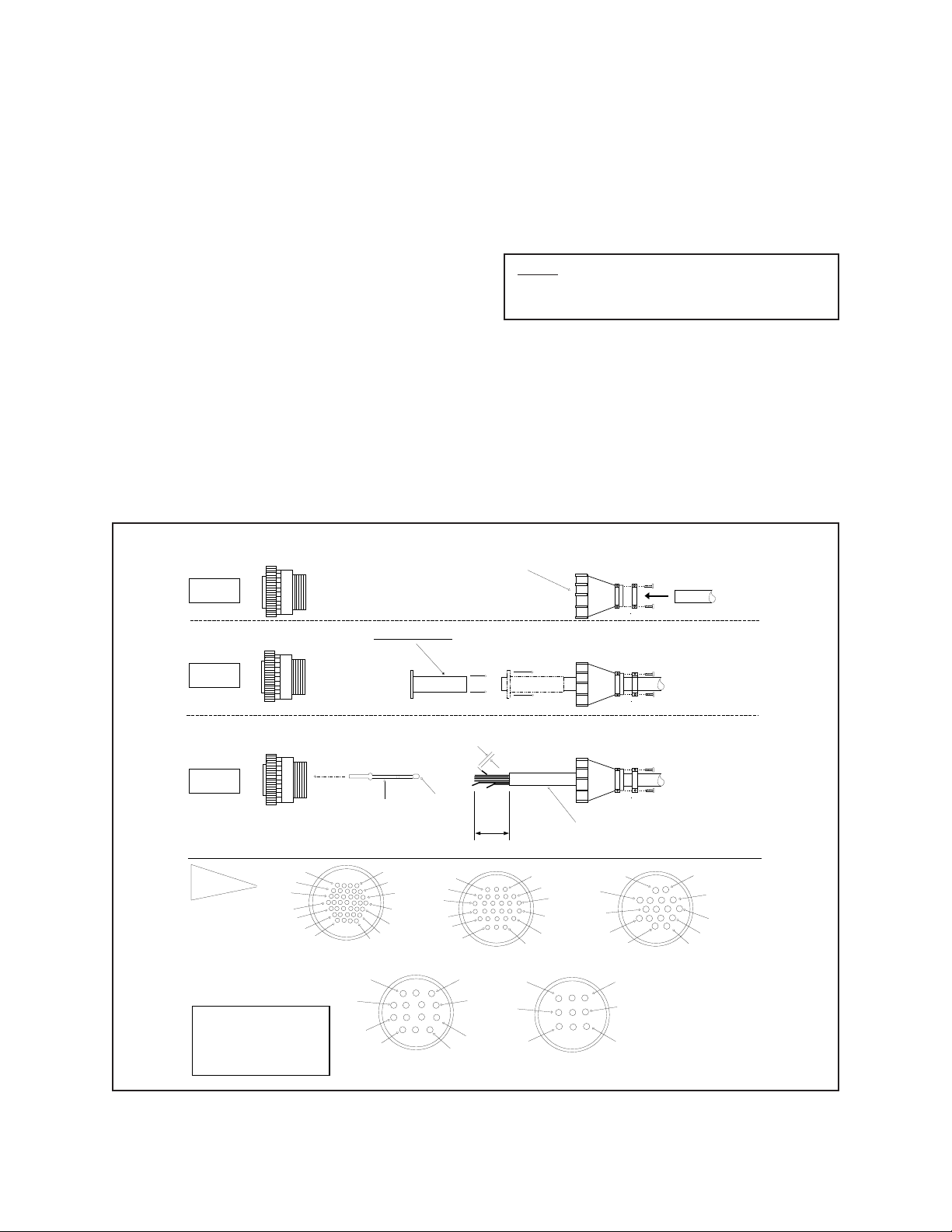
4.2 CONNECTOR ASSEMBLY
Installation and/or testing will require you to assemble
the connector parts provided. Fabricate the interconnecting cable according to the following steps (reference Figure 4).
1. Slide part A of the cable clamp (item 1) over
the end of the cable (item 1, part C) with the
threaded end of the cable clamp facing the connector (item 5).
4. The contact pins supplied with the mating connector are the “crimp” type which may also
be soldered if you so desired (item 4).
5. After crimping or soldering the contact pins
to the conductors, push them into the proper
holes in the connector until they snap in place.
Note: Contacts cannot be removed from the connector without the use of the appropriate AMP extraction tool which is available from PELCO.
2. If the cable has a diameter less than 1/2 inch
(1.3 cm), slide the rubber boot (item 2) over
the end of the cable and pull through the cable
clamp to so that the boot encases the cable and
forms a good seal.
3. Strip back the cable jacket approximately 11/4 inches (3.2 cm) and separate the individual
conductors (item 3).
5
STEP 1
FLEXIBLE RUBBER BOOT
4
CRIMP
WIRE
1
29
34
3
7
11
14
14-PIN CONNECTOR
5
10
16
23
FRONT VIEW
CRIMP
INSULATION
14
20
STEP 2
STEPS 3-7
**
ITEM 5 DETAIL
THE MOST COMMONLY USED
CONNECTOR PIN-OUT CONFIGURATIONS ARE SHOWN HERE.
REFERENCE THE CONNECTOR
DRAWING APPLICABLE TO
YOUR SITUATION.
5 1
5 **
4
9
15
22
28
33
37
FRONT VIEW
37-PIN CONNECTOR
2
3
8
25
28
12
threaded end of
cable clamp
STRIP 1/8"
STRIP 1"
FRONT VIEW
28-PIN CONNECTOR
1
4
8
6. Slide part A of the cable clamp toward the connector and screw the parts together. Attach part
B (item 1) onto part A and connect both parts
with the screws provided.
7. Connect the cable assembly to the unit and
seat the connector by twisting the locking collar until it snaps into position (see Figure 5
and Figure 10).
1
A B C
A B
C
3
3
6
OUTSIDE
JACKET
OF CABLE
1
4
9
15
21
26
FRONT VIEW
9-PIN CONNECTOR
6
10
14
1
A B
2
16
FRONT VIEW
16-PIN CONNECTOR
1
4
79
C
1
3
7
11
15
Figure 4. Connector Assembly
Pelco Manual C550M-E (8/97) 5
shown in the
"Short" position
37-PIN
AMP CONNECTOR
POWER INPUT
PC BOARD
SW 1P2
P1
BNC
CONNECTORS
COAXITRON SYSTEM 2000
RECEIVER
RECEIVER CONTROL
INPUT PIN
ASSIGNMENTS
(P1 & P2 ARE
LOCATED ON
P1
THE COAXITRON
RECEIVER CARD)
3 BRN P/T COM 1
5 ORG LEFT 3
8 4
7 GRN DOWN 5
6 BLU UP 6
4 VIO RIGHT 7
9 GRAY GROUND 8
*
RECEIVER CONTROL
OUTPUT PIN
ASSIGNMENTS
(GOING TO THE
37-PIN AMP
CONNECTOR)
12 BLACK IRIS 10 1
11 W/BRN FOCUS 11 3 LENS
10 W/RED ZOOM 12 2 INPUT
14 W/ORG LENS COM 13 4
13 RED MAN IRIS 2 5
1 WHITE CAM AC HIGH 9 CAMERA
2 W/YEL CAM AC LOW 14 INPUT POWER
P2
10 BRN/W +21V 28
9 RED/W CAM ON 29
8 ORG/W AUX 1 30 AUXILIARY
7 YEL/W CAM OFF 31 WIRING
6 GRN/W AUX 4 32 PROVIDED IN
5 BLU/W AUX 3 33 OUTDOOR
4 VIO/W AUX 2 34 MODELS ONLY
3 GRY/W LOGIC RESET 35
2 W/GRY GROUND 36
1 BLK/W +10V 37
For REV K boards, the SW1 switch position is the reverse of that shown
*
above; i.e., "short" is "long" and "long" is "short". See page 8 for further details.
Figure 5. Receiver Control Output/Input Pin Assignments
NOTE: CONSULT
FACTORY BEFORE
ATTEMPTING TO USE
AUX FUNCTIONS.
EXTERNAL REQUIREMENTS ARE NEEDED.
6 Pelco Manual C550M-E (8/97)

4.3 SYSTEM CONFIGURATIONS
Figure 6 shows the simplest system configuration utilizing the Coaxitron System 2000. This system consists of
the control transmitter, coax cable and receiver/camera.
This basic Coaxitron system is flexible in that it can be
expanded to control multiple camera sites when a hard
contact switching device is added.
COAXITRON
TRANSMITTER
COAXITRON
TERMINATE MONITOR
Figure 7 shows the addition of a manual video switcher
and one receiver/camera. In this example, the active
coaxial cable is terminated in the transmitter and the
inactive cables are terminated in the switcher. The
selected camera signal is fed to the Coaxitron transmitter, which then feeds the monitor. When a camera
selection is made, that video line is dedicated to the
transmitter that allows the associated Coaxitron receiver to be controlled. Functions such as auto/random
are latching and will remain on until turned off by the
transmitter.
VIDEO
COAXITRON
RECEIVER
SIGNAL
MULTI-CONDUCTOR
CABLE
TERMINATE MONITOR
Figure 6. Basic Coaxitron System 2000
COAXITRON
TRANSMITTER
COAXITRON
MANUAL
SWITCHER
COAXITRON
RECEIVER
COAXITRON
RECEIVER
VIDEO
SIGNAL
MULTI-CONDUCTOR
CABLE
VIDEO
SIGNAL
MULTI-CONDUCTOR
CABLE
Figure 7. Coaxitron System 2000 with Manual Video Switcher and Multiple Cameras
Pelco Manual C550M-E (8/97) 7

A more complex system is shown in Figure 8. Here,
several control locations can serve a single camera
system.
Note: All transmitters, except the last one, must
be looping (unterminated) rather than terminating.
This monitor may also be used for sequential switching.
As in the previous configuration, any one transmitter
can assume control. If two or more control units are
activated simultaneously, erroneous responses are prevented by error detection circuitry in the associated
receiver.
In a system of this type, any one of the transmitters can
assume control because there is no priority provision. If
two or more transmitters are activated simultaneously,
error detection circuitry in the receiver will cause multiple commands to be ignored.
Figure 9 shows an even more complex system. In this
example, multiple transmitters are controlling multiple
receivers.
Note: All but the last transmitter and associated
switcher must be looping (unterminated). Transmitters and associated switchers should be physically adjacent to insure against signal deterioration
due to cable mismatch.
Video cables from the receivers are looped through the
first control station to the second. At the first control
station, a bridging-looping type sequential switcher
(except VA500 series) is used. The Monitor 2 output is
a hard contact switch, otherwise known as the bridged
output for continuous viewing or control selection.
The switchers depicted in Figure 10 are hard contact
devices and do not have isolation or bridging amplifiers.
In each case, the Coaxitron transmitter acts as the
isolation or bridging amplifier. Do not use VA500
series switchers with Coaxitron systems.
Note: For configurations where RG59 cable
length between the transmitter and receiver exceeds 750 feet, it is necessary to reset switch SW1
on the receiver board (PCB1500529) from SHORT
to LONG. The switch should be left in the SHORT
position when using shorter lengths of RG59 cable
or when using RG11 cable (see Figure 5). For
RG11 cable, the upper limit is 1800 ft. In any case,
these operating distances can be extended by using
the EA2000. See the table on page 26.
Coaxitron System 2000 basic interconnections between
the transmitter and receiver are shown in Figure 10. If
you have chosen a configuration that includes a switching device, refer to the manual provided with the switcher
for the appropriate connections.
TERMINATE MONITOR
VIDEO
SIGNAL
MULTI-CONDUCTOR
CABLE
TERMINATE MONITOR
TERMINATE MONITOR
COAXITRON
TRANSMITTER
UNTERMINATED
TRANSMITTER
COAXITRON
TRANSMITTER
UNTERMINATED
TRANSMITTER
COAXITRON
TRANSMITTER
COAXITRON
RECEIVER
Figure 8. Coaxitron System 2000 with Multiple Transmitters
8 Pelco Manual C550M-E (8/97)

COAXITRON
TRANSMITTER
COAXITRON
TRANSMITTER
COAXITRON
LOOPING
SWITCHER
TERMINATING
SWITCHER
COAXITRON
RECEIVER
COAXITRON
RECEIVER
VIDEO
SIGNAL
MULTI-CONDUCTOR
CABLE
VIDEO
SIGNAL
MULTI-CONDUCTOR
CABLE
Figure 9. Coaxitron System 2000 with Multiple Transmitters and Receivers
RECEIVER VIDEO CABLE
RECEIVER
INPUT FROM CAMERA
RECEIVER
VIDEO CABLE
OUTPUT TO
TRANSMITTER
RECEIVER
CONTROL OUTPUT
TO PAN AND TILT/
LENS
24/120/230 VAC
(AMP SERIES CPC
OUTPUT CONNECTOR)
VIDEO CABLE
TRANSMITTER
AC INPUT
120 VAC
230 VAC
F1
.2 ASB
LOOPING
OUTPUT
J8 J7 J6
VIDEO
INPUT FROM
RECEIVER
OUTPUT TO
MONITOR
TO ADDITIONAL
CONTROL TRANSMITTERS
OR TERMINATE
Figure 10. Coaxitron System 2000 Basic Interconnect Diagram
Pelco Manual C550M-E (8/97) 9

5.0 OPERATION
In general, all operating controls on the transmitter are
self explanatory. With the exception of the ON/OFF
power switch and the 8-position joystick, all controls
are center-off, spring return paddle switches (momentary on-off-on).
5.1 FUNCTIONAL CIRCUIT DESCRIPTION
The basic functional concept of the Coaxitron system is
that 15 control pulses are fed in a reverse direction from
the control transmitter to the receiver located near each
camera station. These control pulses do not interfere
with the video monitor presentation because they occur
during the vertical blanking interval of the video signal.
The equipment is designed to operate with video cable
lengths up to 750 feet of RG59B/U (or equivalent), or up
to 1,800 feet of RG11. The SW1 switch prominently
located on the receiver board (PCB1500529), should be
moved to the LONG position when RG59B/U cable of
greater than 750 feet is used (see Figure 3).
Cable impedance matching is insured by the video
amplifier in the control receiver. Proper receiving
and termination impedance is likewise insured by the
terminating resistor in the control transmitter.
Any equipment placed between the remote and local
locations must be of the “loop-through” or “bridging”
type; power splitter or line amplifiers cannot be tolerated.
Response time of the system is normally less than 30
ms. Error detection circuitry is incorporated to immunize the system from externally generated noise. Under
extremely adverse environmental noise conditions response time may increase, and in the limit, control
functions can fail. Under such extreme conditions,
however, provision is made to inhibit all momentary
functions.
The proper function of the Coaxitron system depends
on the compatibility of two signals simultaneously
traveling in opposite directions in the same coaxial
cable. If the control signal is made large, compared to
the video signal, there is the risk that associated equipment will be adversely affected. If the control signal is
made small, compared to the video signal, it becomes
difficult to separate it from the video signal (and any
incumbent noise or hum). Therefore, the Coaxitron
system is designed to function with video and control
signals nominally equal.
Under such circumstances, reliable performance can be
predicted with cable lengths of 1,500 feet or more.
Beyond this distance, the control signal amplitude can
become attenuated sufficiently to make performance
marginal. Marginal performance is also approached if
the video signal is allowed to become excessive — the
dynamic range of the receiver video amplifier is one
limitation. Sending end distortion produced by the
coaxial cable is typically the major contributor to the
malfunctioning of a Coaxitron system. The amplitude
of distortion products is proportional to video signal
amplitude and is a non-linear function of cable length.
The influence of these distortion products upon system
performance is difficult to predict if signal amplitude is
allowed to exceed specifications.
Normally, auto-target or auto-iris functions will maintain a video level well within reasonable limits and
insure reliable performance. Often, however, automatic
or manual level settings may be made abnormally high
(perhaps to compensate for long cable losses or to
produce a picture with more contrast). An excessively
high video level setting can cause the Coaxitron control
system to fail completely — with all control functions
disabled. In order to prevent system failures due to
excessively high video levels, it is recommended that
cameras be powered by the receiver.
The Coaxitron System 2000 is designed to combat
prolonged loss of control due to the conditions described above by providing the following protective
functions:
1. Simultaneous commands from two different
sources are processed to insure that manual iris
control cannot be inadvertently selected in
place of automatic control.
2. A sustained (20 to 40 second) illegal command
condition results in (a) camera off,
(b) automatic iris, or (c) manual pan.
These functions greatly reduce the possibility of loss of
control and usually eliminate the need for service.
10 Pelco Manual C550M-E (8/97)

As an example, assume that the operator switches to
manual iris control and proceeds to open the iris excessively. The result can be a complete loss of control.
Within 20 to 40 seconds, camera power is automatically
removed (assuming this feature exists) and auto iris is
reinstated. Thus, distortion products are eliminated if
the camera power function is incorporated in the system
or reduced to a tolerable level if only the AUTO/
MANUAL iris function is incorporated.
5.2 TRANSMITTER
The transmitter is housed in a 1-3/4" high enclosure,
supplied as a desk top unit (rack mount available). Three
video connectors (J6, J7, J8) are located on the rear rail
(see Figure 10). J8 allows the user to loop the camera
signal from one transmitter to another, or to terminate
the signal by installing the appropriate resistor. Connector J7 accepts the camera signal from the receiver, and
J6 provides an output for monitoring equipment.
5.2.1 Controls
Power ON/OFF Rocker switch
Pan/Tilt 8-position joystick
Zoom Paddle switch Tele/Wide
Focus Paddle switch Near/Far
Iris Paddle switch Open/Close
Aux 1,2 Paddle switch Auto/Manual
Iris (latching function)
Camera Power Paddle switch On/Off (latching
function)
Pan Auto/Man Paddle switch Manual/Auto
(latching function)*
surface for entry of AC power line (120/230/24 VAC).
(See Figure 10.)
The INPUT video connector accepts the signal from the
camera and provides a 75 ohm termination.
The OUTPUT video connector is connected to the
transmitter input connector (J7) via a dedicated and
continuous coaxial cable. Proper termination of this
cable is vital to the operation of the equipment. Although loop-through connections in this cable are permissible, power splitter or line amplifiers cannot be
tolerated.
5.4 RECEIVER/TRANSMITTER
INPUTS AND OUTPUTS
The Receiver/Transmitter inputs and outputs are described as follows:
• Receiver Video Input
Normally, this is the video signal from the camera serviced by the receiver. The receiver provides a 75 ohm cable termination and an isolation
amplifier to prevent the control pulse train from
being fed to the camera. (See Figure 10.)
• Receiver Video Output
This output is fed to the transmitter video input
(J7) via 75 ohm coaxial cable. Active elements
or “splitters” in this cable run cannot be tolerated. (See Figure 9.)
• Receiver Power Input
All Coaxitron receivers may be powered by 24/
120/230 VAC as ordered from the factory.
The AC power input for 24 VAC operation must
be changed as described in Section 4.1.
Aux 3, 4 Paddle switch (momentary
functions)*
*External requirements are needed for operation
5.3 RECEIVER
The receiver and control function assemblies are contained in a “J-Box” housing. One end of the J-Box has
two video connectors (input and output) and CPC-type
control cable connector. Provision is made on this same
Pelco Manual C550M-E (8/97) 11
• Receiver Control Output
All control signals from the receiver are available from an AMP Series CPC output connector,
except for optional auxiliary functions. (See
Figure 10.)

• Receiver Control Output for 12 VDC Camera
Option
The usual output for camera power is 24 VAC
accessed at pins 9 and 14 of the 37-pin AMP
connector (see Fig. 5) where CAM AC HIGH
and AC LOW emerge as CAMERA INPUT
POWER. The output pin assignments remain the
same for 12 VDC camera power options, only
now pin 9 (WH) is positive (+) and pin 14 (WH/
YEL) is negative (-).
• Transmitter Video Input
The transmitter usually provides for the 75 ohm
termination of the cable from the receiver. However, the user may alter this termination in order
to loop through and terminate further downstream. (See Figure 10.)
WARNING: Power for enclosure models utilizing heater/blowers cannot be tapped off the secondary of the Coaxitron receiver transformer or off
of camera AC power (see Figure 5, Pins 9 and 14).
Instead,for example, enclosure power for these
purposes could be run off of the primary of the
Coaxitron transformer and routed to the enclosure
via unused Pins 15 and 16 of the 37-Pin connector.
Although the Coaxitron control system is immune to
transient or surge disturbances, its performance can be
impaired by the presence of large ground loop voltages
between the transmitter and the receiver. The amplitude
of ground loop potential that can be tolerated varies as
a complex function of cable center conductor resistance, video signal amplitude, and cable length. However, ground loop voltages that induce less than 0.5 volt
p-p into the video output of the receiver should not cause
the system to malfunction.
Factors that limit the distance over which the Coaxitron
can be used are transmission line attenuation and transmission line signal distortion
When signal attenuation becomes large due to excessive cable length, the differential amplifier in the
Coaxitron receiver can no longer detect the presence of
a control pulse train. The limitation can be overcome by
increasing the amplitude of the pulses generated by the
transmitter. This is not done without danger, however,
because associated equipment may be over-driven by
the larger signal. (Note that the presence of the control
signal is not restricted to the cable between the transmitter and receiver, but will be on all signal cables downstream from the receiver.)
It has been stipulated that loop-through connections are
permissible in the control link, and distribution or
equalizing amplifiers are not because of their
undirectional characteristics.
Pre-equalization of the camera signal prior to feeding to
the Coaxitron receiver is generally not practical because
of the dynamic limits in the receiver video amplifier.
Post equalization of the signal (transmitter output signal) is permissible, but probably not practical. It should
be kept in mind that although the camera signal has been
deteriorated by the transmission line, the control signal
has not. Therefore, the equalized control pulses will be
extremely large and probably cause an overload in some
part of the system downstream from the equalizing
amplifier.
In the absence of an assertive control command, the
transmitter is inactive. Thus, it is possible to control one
receiver from more than one control.
5.5 COAXITRON PREPOSITION
RECEIVER
In general, ground loop problems will seldom be encountered. However, potentials as high as 10 volts p-p
between ground connections within a single building
are not unheard of. If such circumstances arise, Pelco
recommends the use of its Model GIT100 Ground
Isolation Transformer. When inserted in the cable run
between two points of different ground potential, the
effect of this potential difference on the video signal is
reduced by more than 100 times with 200 feet, and more
than 20 times with 1,500 feet of RG59 type cable. More
than one GIT100 can be utilized in situations where the
common mode voltage (CMV) exceeds 10 volts p-p.
This transformer is passive and can easily be inserted
where required at any time.
12 Pelco Manual C550M-E (8/97)
Note: The Coaxitron preposition receiver is
designed for use with Coaxitron Matrix controls
only.
The Coaxitron System utilizes linear taper precision
potentiometers as the position feedback sensors. This
feedback voltage is digitized and stored in the receiver.
The storage of the presets is held in EEPROM and is
therefore nonvolatile.

Up to 32 presets can be stored in each receiver. Up to 8
T
presets can be activated by alarm contacts connected to
the receiver. There is also an open collector output from
the receiver to activate an external device (such as the
CSA764) when the alarm contacts are activated. Figure
11 shows the wiring for alarmed presets.
The pan/tilt will “nod yes” if the receiver reads the
feedback voltages (preposition lens) or “nod no” if it
does not read any feedback voltages (manual lens).
This routine is a good troubleshooting indicator of
incorrect wiring of the control cable.
If multiple alarms are activated, the receiver will sequence between the alarm presets at a 5 second dwell
time per preset.
Figures 12 through 14 provide pin-to-pin connections
for preset domes, pan/tilts and lenses to the Coaxitron
receiver that are available at this revision manual.
5.5.1 Power-up Routine
When a preposition receiver is first powered up, it has
a routine that it goes through to orient itself to the pan/
tilt and lens connected to it.
The routine first automatically operates the lens “zoom”
and “focus” functions.
NOTE: ALARM OUTPUT MUST RETURN TO
THE CSA764 FOR THE ALARM CONDITION
TO BE SWITCHED TO THE MONITOR 1
OUTPUT OF THE MATRIX
OAXITRON RECEIVER
37 PIN CONNECTOR
17
ALARM INPUT 1
18
ALARM INPUT 2
19
ALARM INPUT 3
20
ALARM INPUT 4
21
ALARM INPUT 5
22
ALARM INPUT 6
23
ALARM INPUT 7
24
ALARM INPUT 8
25
ALARM OUTPUT
26
ALARM COMMON
ALARM CONTACTS NORMALLY OPEN
The second part of the routine will operate the “pan left”
and “pan right” functions. The pan/tilt will “nod yes” if
it reads only one feedback voltage (pan/tilt with limit
stops) or “nod no” if it reads two feedback voltages (SL
pan/tilt).
The total routine takes approximate 45 seconds to
complete.
5.5.2 Creating Presets
At the present time the only Coaxitron system transmitters capable of creating presets are the CM7500, the
CM9500 Matrix and the MPT9500. Refer to the instructions in the product manuals (C584M, dated 2/90 or
later for CM7500 matrix, or C500M for CM9500 matrix
or C535M for the MPT9500) to create presets, if necessary.
ALARM CONDITION
OPEN COLLECTOR OUTPUT
BACK TO CSA764 ALARM INPU
ALARM COMMON
BACK TO CSA764
Figure 11. Wiring Diagram for Preposition Alarm Outputs
Pelco Manual C550M-E (8/97) 13

Function
SB1900-PP, SB1900SL-PP,
SS2000-PP and SS2000SL-PP
28-pin
Connector
Function
SB2500-PP, SB2500SL-PP,
SB2600-PP and SB2600SL-PP
37-pin
Connector
Function
Preset Unit Only
Coaxitron Receiver
1 Pan/Tilt Common 1 Pan/Tilt Common 1 Pan/Tilt Common
2 Manual Iris 2 Not Used 2 Video Core
3 Pan Left 3 Pan Left 3 Pan Left
4 Video Shield 4 Video Shield 4 Video Shield
5 Tilt Down 5 Tilt Down 5 Tilt Down
6 Tilt Up 6 Tilt Up 6 Tilt Up
7 Pan Right 7 Pan Right 7 Pan Right
8 Ground 8 Ground 8 Ground
9 Camera AC (High) 9 Camera AC (High) 9 Camera AC (High)
11 Focus 11 Focus 11 Focus
10 Iris 10 Iris 10 Iris
12 Zoom 12 Zoom 12 Zoom
13 Lens Common 13 Lens Common 13 Lens Common
14 Camera AC (Low) 14 Camera AC (Low) 14 Camera AC (Low)
15 Not Used 15 Not Used 15 Not Used
16 Not Used 16 Not Used 16 Not Used
17 Alarm Input 1 17 Not Used 17 Preset +5V
18 Alarm Input 2 18 Not Used 18 Preset Ground
19 Alarm Input 3 19 Not Used 19 Cam Sync-C
20 Alarm Input 4 20 Not Used 20 Preset Zoom
21 Alarm Input 5 21 Not Used 21 Preset Focus
22 Alarm Input 6 22 Not Used 22 Preset Pan
23 Alarm Input 7 23 Not Used 23 Preset Tilt
24 Alarm Input 8 24 Not Used 24 Preset Pan (SL models only)
25 Alarm Output 25 Not Used 25 Not Used
26 Ground 26 Not Used 26 Not Used
27 Video Core 27 Video Core 27 Not Used
28 Preset Ground 28 Preset Ground 28 Not Used
29 Preset +5 V 29 Preset + 5V
30 Not Used 30 Cam Sync - C
31 Not Used 31 Not Used
32 Not Used 32 Not Used
33 Pan B Preset 33 Preset Pan
34 Preset Focus 34 Preset Focus
35 Preset Zoom 35 Preset Zoom
37-pin
Connector
14 Pelco Manual C550M-E (8/97)
36 Preset Tilt 36 Preset Tilt
Figure 12. SB1900, SS2000, SB2500 and SB2600 Series Preset Wiring Diagram
37 Pan A Preset (360) 37 Preset Pan (SL models only)

Function
28-pin
Series Domes/ PT1280P/PP and PT1280SL/PP
Connector
Preposition Pan/Tilts PT280, PT680 Series and SB2800
Function
Preposition Pan/Tilts
PT520, PT550, PT570 and PT1250 Series
37-pin
Connector
Function
Preset Unit Only
Coaxitron Receiver
1 Pan/Tilt Common 1 Pan/Tilt Common 1 Pan/Tilt Common
2 Manual Iris 2 Preset Pan 2 Video Core
3 Pan Left 3 Pan Left 3 Pan Left
4 Video Shield 4 Video Shield 4 Video Shield
5 Tilt Down 5 Tilt Down 5 Tilt Down
6 Tilt Up 6 Tilt Up 6 Tilt Up
7 Pan Right 7 Pan Right 7 Pan Right
8 Ground 8 Ground 8 Ground
9 Camera AC (High) 9 Preset Tilt 9 Camera AC (High)
11 Focus 11 Preset +5 V 11 Focus
10 Iris 10 Preset Ground 10 Iris
12 Zoom 12 Not Used 12 Zoom
13 Lens Common 13 Not Used 13 Lens Common
14 Camera AC (Low) 14 Not Used 14 Camera AC (Low)
15 Not Used 15 Not Used 15 Not Used
16 Not Used 16 Not Used 16 Not Used
17 Alarm Input 1 17 Preset Ground
18 Alarm Input 2 18 Preset + 5 V
19 Alarm Input 3 19 Preset Pan
20 Alarm Input 4 20 Preset Tilt
21 Alarm Input 5 21 Not Used
22 Alarm Input 6 22 Not Used
23 Alarm Input 7 23 Preset Zoom
24 Alarm Input 8 24 Preset Focus
25 Alarm Output 25 Preset Pan (SL models only)
26 Ground 26 Not Used
27 Video Core 27 Not Used
28 Preset Ground 28 Not Used
29 Preset +5 V
30 Not Used
31 Not Used
32 Not Used
33 Pan B Preset
34 Preset Focus
35 Preset Zoom
37-pin
Connector
Pelco Manual C550M-E (8/97) 15
36 Preset Tilt
Figure 13. PT280, PT520, PT550, PT570, PT680, PT1250, PT1280 and SB2800 Series Preset Wiring Diagram
37 Pan A Preset (360)

Coaxitron Receiver
Preset Unit Only
37-pin 9-pin
Connector Function Connector Function
1 Pan/Tilt Common 1 Iris
2 Manual Iris 2 Zoom
3 Pan Left 3 Focus
4 Video Shield 4 Lens Common
5 Tilt Down 5 Ground
6 Tilt Up 6 Preset +5V
7 Pan Right 7 Preset Zoom
8 Ground 8 Preset Ground
9 Camera AC (High) 9 Preset Focus
10 Iris
11 Focus
12 Zoom
13 Lens Common
14 Camera AC (Low)
15 Not Used
16 Not Used
17 Alarm Input 1
18 Alarm Input 2
19 Alarm Input 3
20 Alarm Input 4
21 Alarm Input 5
22 Alarm Input 6
23 Alarm Input 7
24 Alarm Input 8
25 Alarm Output
26 Ground
27 Video Core
28 Preset Ground
29 Preset +5 V
30 Not used
31 Not used
32 Not used
33 Pan B Preset
34 Preset Focus
35 Preset Zoom
36 Preset Tilt
37 Pan A Preset (360)
Preposition Lenses
Figure 14. Lens Preset Wiring Diagram
16 Pelco Manual C550M-E (8/97)

5.6 AUXILIARY FUNCTIONS
The Coaxitron receiver is capable of operating up to
four (4) remotely activated auxiliary functions. Each
auxiliary output may be individually converted at the
receiver for momentary or latching operation. Refer to
Figure 15 for the desired jumper location. When in the
latching mode, activating the same AUX function will
toggle the function from on to off.
The AUX outputs are buffered to provide a continuous
10 VDC at 25 mA to drive small relays, lamps or some
other external device. Refer to Figures 16 and 17 for
examples of typical circuits used for auxiliary functions.
Note: The preceding two paragraphs pertain to
Revision J or newer Receiver/Driver Mother boards.
Figure 18 shows a typical connection using the latching
command to operate an AI700 or AI701 for auto iris or
manual iris operation. AUX 1 latches manual iris; AUX
2 latches auto iris.
Latching
**
For Revision K (REVK)
boards, SW1 positions are
reversed; i.e., the position
shown above is the "Long"
position for REVK boards.
AUXILLARY JUMPER
SETTINGS ON THE
COAXITRON RECEIVER
BOARD. JUMPERS ARE
SHOWN IN THE
MOMENTARY "POSITION"
OR "MODE".
JP4
JP3
JP1
JP2
AUX 4
AUX 1
AUX 2
AUX 3
Momentary
P1
PC BOARD
P2
"Short" position
BNC
CONNECT ORS
shown in the
SW1
COAXITRON SYSTEM 2000
37-PIN
AMP CONNECTOR
POWER INPUT
**
RECEIVER
Figure 15. Jumper Settings, Receiver/Driver Mother Board
Pelco Manual C550M-E (8/97) 17

COAXITRON
RECEIVER/DRIVER
37-PIN CONNECTOR
1
+ 12 VDC
1N4005
NORMALLY-OPEN
CONTACTS
10 VDC RELAY
25 mA COIL
CURRENT MAXIMUM
2
MANUAL IRIS
NOTE: CUSTOMER SUPPLIES PARTS AND 12 VDC
POWER SUPPLY
3
8
GROUND
Figure 16. External Device Wiring Diagram
CONNECT TO NEGATIVE
SIDE OF 12 VDC SUPPLY
18 Pelco Manual C550M-E (8/97)

30
34
33
32
36
RECEIVER/DRIVER
AUXILIARY FUNCTIONS
TYPICAL WIRING CONNECTIONS
10 VDC RELAY
25 mA COIL
CURRENT MAXIMUM
10 VDC RELAY
25 mA COIL
CURRENT MAXIMUM
10 VDC RELAY
25 mA COIL
CURRENT MAXIMUM
1N4005
1N4005
1N4005
10 VDC RELAY
25 mA COIL
CURRENT MAXIMUM
AUX 1 CONTACTS
AUX 2 CONTACTS
AUX 3 CONTACTS
AUX 4 CONTACTS
NOTE: CUSTOMER MUST SUPPLY PARTS
Pelco Manual C550M-E (8/97) 19
Figure 17. Auxiliary Functions Wiring Diagram

1
2
3
10
11
12
13
MANUAL IRIS
37 PIN CONNECTOR
IRIS
FOCUS
ZOOM
LENS COMMON
1
2
3
4
5
1
2
3
4
5
1
2
3
4
5
1
2
3
4
5
LENS CABLE
LENS CABLE
TO COAXITRON RECEIVER
COAX COAX
AUX 1 COMMAND LATCHES MANUAL IRIS CONTROL
AUX 2 COMMAND LATCHES AUTO/IRIS CONTROL
CAMERA
LENS
AI700 OR AI701 WIRING CONNECTION
TO THE COAXITRON RECEIVER
LENS CABLE
AI700 OR AI701
20 Pelco Manual C550M-E (8/97)
Figure 18. AI700/AI701 Wiring Diagram

5.7 AUTO/RANDOM OPERATION
The A9000 Auto/Random Scan module is a plug-in
P.C. board option (See Fig. 19 for board location) for all
Coaxitron receivers. This module provides two modes
for automatically controlling pan and tilts within preset
limits — Auto Scan and Random Scan. The Random
Scan and Auto Scan functions are controlled by the
same momentary switch on the control panel labeled
AUTO and MAN. The first activation of the switch to
the AUTO position will put the pan/tilt into Random
Scan. In Random Scan operation the pan/tilt will travel
between the preset limits with a random scan period of
about 0 to 60 seconds, and a random dwell period of
between about 4 seconds and a programmable 60 to 900
seconds. At the completion of a dwell period, another
random scan period is started. The direction of this scan
period is also randomly determined. When a pan limit is
reached, scan direction is reversed automatically. A
second activation of the AUTO switch will put the pan/
tilt into continuous duty Auto Scan. After approximately 1/2 hour of auto scan, the circuit will reset to
random scan. Commanding AUTO while in Random
mode causes a shift to Auto mode and starts the halfhour timer. Similarly, commanding AUTO while in
Auto mode causes a shift to the Random mode and zeros
the half-hour timer.
Advantages of random scan:
1. Because scan direction, scan period and dwell
period are unpredictable, unauthorized activities or intrusions are discouraged.
2. Because of the reduced duty cycle, gear train
wear, cable fatigue, drive motor wear and
temperature rise are reduced. These factors all
contribute to higher system reliability and increased equipment life.
2. Insert spacers into appropriate holes in the
motherboard and snap firmly into place.
5.8 CX900TLC MANUAL/TEST MODULE
The CX900TLC Manual/Test Board is a dual purpose
plug-in module (See Fig. 19 for board location) which
permits local operation of all functions directly from the
receiver unit, and also serves to verify that the receiver
and accessories are operating properly by providing
visual confirmation. This module also aids in troubleshooting receiver or transmitter operational problems.
See Figure 21 for module functions and wiring schematic.
P3
1
TEST
MODULE
CX900TLC
22
AUTO/RANDOM SCAN MODULE
AC
LOW
A9000
AC
GRN
HIGH
RECEIVER BOARD
RX90001000ASSY (24 VAC)*
RX90001007ASSY (120/220 VAC)*
(*VOLTAGES REFER TO
OUTPUT (P/T), CAMERA.)
8
J2
1
P5
F2 F1F3
14
1
P1
P2
1
10
The A9000 auto/random scan plug-in module comes
equipped with an 8-pin male connector and two nylon
spacers factory installed. To install the module perform
the following steps:
3 2 1
A.C. INPUT
VIDEOINVIDEO
OUT
OUTPUT
WARNING: Power must be removed from receiver prior to installing A9000. Destructive fail-
CAUTION: HAZARDOUS VOLTAGE MAY EXIST.
ure of A9000 may result if it is plugged into a
powered motherboard.
1. Locate the 8-pin female connector (J2) on the
motherboard and insert the 8-pin male connector (P5). See Figure 20 for wiring schematic.
Figure 19. Coaxitron Receiver Assembly Layout
(Top View)
Pelco Manual C550M-E (8/97) 21

Figure 20. A9000 Wiring Schematic
U1
1N914
1
2
8
3
R1
100K
+10
GND
ACTIVE
14
15
U1
CD4049
U1
U1
U1
U1
R2
820
LED 1
12
10
6
4119
7
5
AUTO
SCAN
CAM
ON
AUX 4
AUTO
IRIS
AUX 2
IRIS
CLOSE
FOCUS
NEAR
ZOOM
WIDE
DOWN
RIGHT
LEFT
UP
ZOOM
TELE
FOCUS
FAR
IRIS
OPEN
AUX 1
MAN
IRIS
AUX 3
CAM
OFF
MAN
SCAN
S1
S2
S3
S4
S5
S6
S7
S8
S9
S10
S11
S12
S13
S14
S15
S16
S17
S18
S19
RIGHT
DOWN
ZOOM
WIDE
FOCUS
NEAR
IRIS
CLOSE
AUX 2
AUTO
IRIS
AUX 4
CAM ON
AUTO
SCAN
LEFT
UP
ZOOM
TELE
FOCUS
FAR
IRIS
OPEN
AUX 1/MAN IRIS
AUX 3
CAM
OFF
MAN
SCAN
20
21
22
1
2
3
4
5
6
7
8
9
10
11
12
13
14
15
16
17
18
19
20
21
22
U1
R1
CR1
R2
CR2
LED
INDICATOR
7
8
1
2
3
4
5
6
9
10
11
12
14
15
16
17
18
1913INTERCONNECT TO RECEIVER
BOARD PCB1500529
P3
22 Pelco Manual C550M-E (8/97)

LEFT
UP
1
2
ZOOM
3
TELE
4
5
6
FOCUS
7
FAR
8
9
IRIS
10
OPEN
11
12
13
AUX 1/MAN IRIS
14
15
16
17
18
19
AUX 3
20
21
22
CAM
OFF
MAN
SCAN
U1
INTERCONNECT TO RECEIVER
BOARD PCB1500529
P3
1
2
3
RIGHT
DOWN
4
5
6
7
10
12
11
13
14
15
8
9
ZOOM
WIDE
FOCUS
NEAR
IRIS
CLOSE
AUX 2
AUTO
IRIS
16
17
18
19
ACTIVE
20
21
+10
22
LED
INDICATOR
GND
R1
CR1
R2
AUX 4
CAM ON
AUTO
SCAN
CR2
S1
S2
S3
S4
S5
S6
S7
S8
S9
1N914
3
U1
S10
LEFT
UP
ZOOM
TELE
FOCUS
FAR
IRIS
OPEN
AUX 1
MAN
IRIS
AUX 3
CAM
OFF
MAN
SCAN
1
2
8
S11
S12
S13
S14
S15
S16
S17
S18
S19
R1
100K
RIGHT
DOWN
ZOOM
WIDE
FOCUS
NEAR
IRIS
CLOSE
AUX 2
AUTO
IRIS
AUX 4
CAM
ON
AUTO
SCAN
11
U1
9
U1
7
U1
5
U1
14 15
U1
CD4049
12
10
6
R2
820
4
LED 1
Figure 21. CX900TLC Test Module and Wiring Schematic
6.0 TROUBLESHOOTING GUIDELINES
If you experience operating problems with either the
receiver or transmitter, first check all fuses and voltage
readings to make sure they are in working order. The
CX900TLC can be utilized to verify receiver functions
and accessories are operational.
7.0 MAINTENANCE
The Coaxitron System 2000 is engineered to provide
years of reliable service. The Coaxitron System 2000
has very few operator serviceable parts and we recommend that system components be serviced by a trained
technician or returned to the factory for repair.
There is little that can be done without the aid of an
oscilloscope. We recommend you contact your local
dealer or our Customer Service Department for assistance.
Copies of the Coaxitron System 2000 Maintenance
Manual (document number C550SM) are available on
request.
Pelco Manual C550M-E (8/97) 23

24 Pelco Manual C550M-E (8/97)
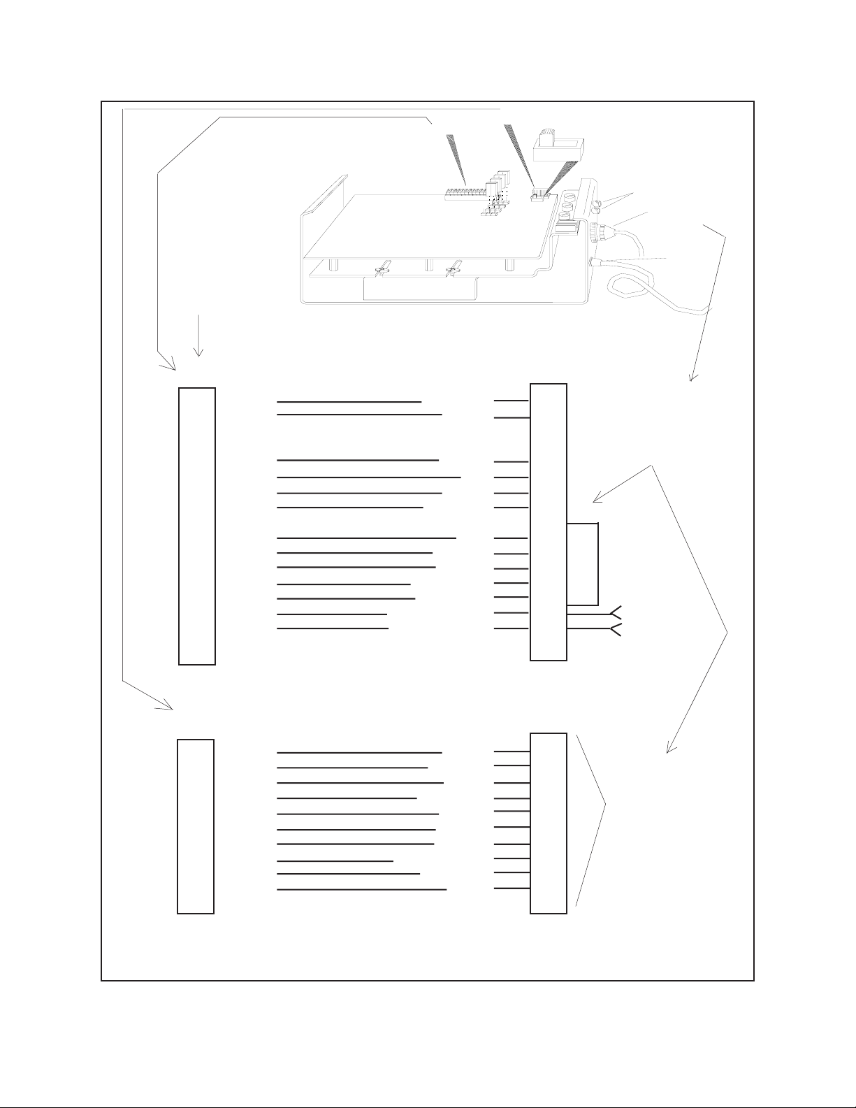
8.0 MODEL NUMBER
TRANSMITTER
WEATHER-PROOF?
INDOOR USE?
24VAC PAN/TILT?
120VAC PAN/TILT?
230VAC PAN/TILT?
Receiver in weatherproof box,
120VAC power input, 24VAC
pan/tilts with power supply
for pan/tilt, zoom lens,
and 4 accessory functions (3
latching, 1 momentary).
CX9024RX
24VAC POWER INPUT?
CX9224RX
Same as CX9024RX except
with 24 VAC power input.
.
PRESETS?
CX9224RX-PP
Same as CX9224RX except
with up to 32 presets for pan/tilt,
zoom and focus functions.
For use with Coaxitron Matrix
controls only.
CX9115RX
PRESETS?
CX9115RX-PP
Same as CX9115RX except
with up to 32 presets for pan/
tilt, zoom and focus functions.
For use with Coaxitron Matrix
Controls only.
12VDC CAMERA POWER?
CX9024RX-12V
PRESETS?
CX9024RX-PP
Same as CX9024RX except with up to 32
presets for pan/tilt, zoom and focus functions.
For use with Coaxitron Matrix controls only.
CX9024RX/220
Same as CX9024RX except 230
VAC operation.
120VAC PAN/TILT?
230VAC PAN/TILT?
CX9024RXI
24VAC POWER INPUT?
CX9224RXI
Same as CX9024RXI except
with 24 VAC power input.
.
PRESETS?
CX9224RXI-PP
Same as CX9224RXI except
with up to 32 presets for pan/tilt,
zoom and focus functions.
For use with Coaxitron Matrix
controls only.
CX9115RXI
PRESETS?
CX9115RXI-PP
Same as CX9115RXI except
with up to 32 presets for pan/
tilt, zoom and focus functions.
For use with Coaxitron Matrix
Controls only.
12VDC CAMERA POWER ?
CX9224RXI-12V
Same as CX9024RXI except
supplied with 12 VDC camera
power.
PRESETS?
CX9024RXI-PP
Same as CX9024RXI except with
up to 32 presets for pan/tilt, zoom
and focus functions. For use with
Coaxitron Matrix controls only.
CX9024RXI-PP/22
Same as CX9024RXI-PP except 230
VAC operation.
Same as CX9024RX except
for indoor use.
24VAC PAN/TILT?
Same as CX9115RX except
for indoor use.
DESK TOP MOUNTED?
RACK MOUNTED?
MPT9000CZ
MPT9000PZ
Transmitter/control with pan/tilt
joystick, zoom lens control, and
4 accessory functions.
Transmitter/control with pan/tilt
joystick, zoom lens control, and
4 accessory functions.
12VDC CAMERA POWER ?
CX9024RXI-12V
Same as CX9024RXI except
supplied with 12 VDC camera
power.
CX9024RXI/220
Same as CX9024RXI except 230
VAC operation.
230VAC PAN/TILT?
230VAC POWER INPUT?
CX9220RX
Same as CX9024RX/220 except
230 VAC power input.
230VAC POWER INPUT?
Same as CX9024RXI/220 except
230 VAC power input.
CX9220RXI
NOTE: Additional combina-
tions of equipment options
are possible depending on
customer need and avail-
ability. This list covers the
most used and/or most
most available type units &
their options.
RECEIVER
TREE LIST
Receiver in weatherproof box,
120VAC power input, 120VAC
pan/tilts with power supply
for pan/tilt, zoom lens,
and 4 accessory functions
(3 latching, 1 momentary).
Same as CX9024RX except
supplied with 12 VDC camera
power.

8.1 OPTIONAL ACCESSORIES
A9000 Auto/random scan, plug-in mod-
ule.
AUX2000 Auxiliary function relay box for
control of wiper/washer functions.
C6806/PP Same as C6806 except for use
with preset pan/tilts.
C6825 Pretested 25 foot (8 m) cable for
use with PT680-24P/PT68024SL pan/tilts. Not for inverted
operation.
AUX9000 Auxiliary function wiring harness.
Required for use with AUX2000
and all indoor Coaxitron/Wiretron
receivers (supplied with outdoor
receivers).
CX900TLC Local test board, plug-in module.
EA2000 Coaxitron equalizing video/con-
trol amplifier. This unit is highly
effective in maintaining picture
quality. See Section 9.0 for specific distances.
8.2 RECOMMENDED CABLES
C1906 Pretested 6 foot (2 m) cable for
use with ED2820, ED2920,
SB2800, SS2000, and SS3000
series enclosures and inverted
PT180-24P, PT280-24P pan/
tilts.
C1906/PP Same as C1906 except for use
with preset pan/tilts.
C1925 Pretested 25 foot (8 m) cable for
use with ED2820/ED2920,
SB2800, SS2000 and SS3000
series enclosures and inverted
PT180-24P, PT280-24P pan/
tilts.
C1925/PP Same as C1925 except for use
with preset pan/tilts.
C2506 Pretested 6 foot (2 m) cable for use
with SB2500 series enclosures.
C2525 Pretested 25 foot (8 m) cable for
use with SB2500 series enclosures.
C6806 Pretested 6 foot (2 m) cable for
use with PT680-24P/PT68024SL pan/tilts. Not for inverted
operation.
C6825/PP Same as C6825 except for use
with preset pan/tilts.
WH1900-06 6 foot (2 m) wire harness pre-
assembled with bare wire and
37-pin connector for use with
SB1900 series enclosures.
WH1900-25 Same as WH1900-06 except 25
feet (8 m) long.
9.0 SPECIFICATIONS
ELECTRICAL
Input Voltage: 120 VAC, 60 Hz Transmitter
and Receiver (strapable for 230
VAC, 50 Hz)
Power
Consumption:
Transmitter 2.5vA
Receiver 5vA (120 VAC or 24 VAC)
Pan/Tilt Supply 140vA Max. (120 VAC)
50vA Max. (24 VAC)
Lens Supply 0-4vA Max.
Camera Supply 15vA (typical)
Control Method: 15-pulse train (pulse width
modulated) superimposed on the
video signal during the vertical
blanking interval by the control
transmitter. Pulse train occupies
1 TV line period.
Pulse Amplitude: Approximately 1V p-p added to
video signal, 333 kHz nominal
Connectors:
Control
Transmitter 3 BNC connectors
Receiver 2 BNC connectors for video in-
put and output
37-pin AMP CPC for control
output (mate supplied)
Pelco Manual C550M-E (8/97) 25

Input Video Level: 1V p-p nominal; 2V p-p maxi-
mum at less than 75% APL;
1.5V p-p maximum at 90% APL
System
Bandwidth: Less than 2 dB down at 10 MHz
(exclusive of cable)
Fuse Protection: 3 AG type
Power Cord: 3-wire grounded #18 AWG,
Transmitter and Receiver
Operating
Distance: Cable distances are approximate
according to cable type used. 75
ohm coax required.
Distance
Cable Type Distance Using EA2000
RG59U 750 ft (229 m) 3,000 ft (914 m)
RG6 1,500 ft (457 m) 4,500 ft (1372 m)
RG11 1,800 ft (549 m) 6,000 ft (1829 m)
RG15 — 8,000 ft (2438 m)
GENERAL
Ambient
Temperature: -4°F to +140°F (-20°C to +60°C)
26 Pelco Manual C550M-E (8/97)

NOTES:
Pelco Manual C550M-E (8/97) 27

10.0 WARRANTY AND RETURN
INFORMATION
WARRANTY
Pelco will repair or replace, without charge, any merchandise proved
defective in material or workmanship for a period of one year after the date
of shipment.
Exceptions to this warranty are as noted below:
• Five years on FT/FR8000 Series fiber optic products.
• Three years on Genex
keyboard).
• Three years on Camclosure
CC3701H-2, CC3701H-2X, CC3751H-2, CC3651H-2X, MC3651H-2,
and MC3651H-2X camera models, which have a five-year warranty.
• Two years on standard motorized or fixed focal length lenses.
• Two years on Legacy®, CM6700/CM6800/CM9700 Series matrix, and
DF5/DF8 Series fixed dome products.
• Two years on Spectra®, Esprit®, ExSite™, and PS20 scanners, includ-
ing when used in continuous motion applications.
• Two years on Esprit® and WW5700 Series window wiper (excluding
wiper blades).
• Eighteen months on DX Series digital video recorders, NVR300
Series network video recorders, and Endura
network-based video products.
• One year (except video heads) on video cassette recorders (VCRs).
Video heads will be covered for a period of six months.
• Six months on all pan and tilts, scanners or preset lenses used in
continuous motion applications (that is, preset scan, tour and auto scan
modes).
Pelco will warrant all replacement parts and repairs for 90 days from the
date of Pelco shipment. All goods requiring warranty repair shall be sent
freight prepaid to Pelco, Clovis, California. Repairs made necessary by
reason of misuse, alteration, normal wear, or accident are not covered
under this warranty.
Pelco assumes no risk and shall be subject to no liability for damages or
loss resulting from the specific use or application made of the Products.
Pelco’s liability for any claim, whether based on breach of contract,
negligence, infringement of any rights of any party or product liability,
relating to the Products shall not exceed the price paid by the Dealer to
Pelco for such Products. In no event will Pelco be liable for any special,
incidental or consequential damages (including loss of use, loss of profit
and claims of third parties) however caused, whether by the negligence
of Pelco or otherwise.
The above warranty provides the Dealer with specific legal rights. The
Dealer may also have additional rights, which are subject to variation from
state to state.
If a warranty repair is required, the Dealer must contact Pelco at (800)
289-9100 or (559) 292-1981 to obtain a Repair Authorization number
(RA), and provide the following information:
1. Model and serial number
2. Date of shipment, P.O. number, Sales Order number, or Pelco invoice
number
3. Details of the defect or problem If there is a dispute regarding the
warranty of a product which does not fall under the warranty conditions
stated above, please include a written explanation with the product
when returned.
Method of return shipment shall be the same or equal to the method by
which the item was received by Pelco.
®
Series products (multiplexers, server, and
®
and fixed camera models, except the
™
Series distributed
RETURNS
In order to expedite parts returned to the factory for repair or credit, please
call the factory at (800) 289-9100 or (559) 292-1981 to obtain an
authorization number (CA number if returned for credit, and RA number
if returned for repair).
All merchandise returned for credit may be subject to a 20% restocking
and refurbishing charge.
Goods returned for repair or credit should be clearly identified with the
assigned CA or RA number and freight should be prepaid. Ship to the
appropriate address below.
If you are located within the continental U.S., Alaska, Hawaii or Puerto
Rico, send goods to:
Service Department
Pelco
3500 Pelco Way
Clovis, CA 93612-5699
If you are located outside the continental U.S., Alaska, Hawaii or Puerto
Rico and are instructed to return goods to the USA, you may do one of the
following:
If the goods are to be sent by a COURIER SERVICE, send the goods to:
Pelco
3500 Pelco Way
Clovis, CA 93612-5699 USA
If the goods are to be sent by a FREIGHT FORWARDER, send the goods
to:
Pelco c/o Expeditors
473 Eccles Avenue
South San Francisco, CA 94080 USA
Phone: 650-737-1700
Fax: 650-737-0933
This equipment contains electrical or electronic components that must be recycled properly to comply with Directive 2002/96/EC of the European Union
regarding the disposal of waste electrical and electronic equipment (WEEE). Contact your local dealer for procedures for recycling this equipment.
28 Pelco Manual C550M-E (8/97)
 Loading...