

Pelco IWP221-1ES, IWP121-1ES User Manual

C2298M-A-EN (10/20)
IWP121-1ES
IWP221-1ES
Sarix® Professional IWP
Series Rugged
Environmental Wedge Dome
User Manual

2

Contents
Important Notices Statement ........................................................................................................................................................ 5
Warranty Statement ..................................................................................................................................................................... 5
Preface ......................................................................................................................................................................................... 6
1. Product Overview .............................................................................................................................................................. 7
1.1 Dimensions .................................................................................................................................................................... 7
1.2 Models Introduction ....................................................................................................................................................... 8
1.3 Physical Characteristics ................................................................................................................................................. 9
2. Installation and Connection ........................................................................................................................................ 10
2.1 Unpacking Everything .................................................................................................................................................. 10
2.2 Installation .................................................................................................................................................................... 10
2.2.1 Checking Appearance ...................................................................................................................................... 10
2.2.2 Connecting the Wires ................................................................................................................................ ....... 10
2.2.3 Disassembling the Camera .............................................................................................................................. 11
2.2.4 Installing the Camera........................................................................................................................................ 12
2.2.5 Adjusting the Camera Position ......................................................................................................................... 13
2.2.6 Sticking Desiccant ............................................................................................................................................ 13
2.2.7 Completing the Installation ............................................................................................................................... 14
2.2.8 Network Topology ............................................................................................................................................ 14
2.2.9 System Requirements ...................................................................................................................................... 15
2.3 Connection ................................................................................................................................................................... 16
2.3.1 Default IP address ............................................................................................................................................ 16
2.3.2 Connecting From a Computer & Viewing Preparation ...................................................................................... 16
3. Administration and Configuration .............................................................................................................................. 18
3.1 Live .............................................................................................................................................................................. 18
3.2 Settings ........................................................................................................................................................................ 19
3.2.1 System ............................................................................................................................................................. 20
3.2.2 Network ............................................................................................................................................................ 23
3

3.2.3 Imaging ............................................................................................................................................................. 34
3.2.4 A/V Streams ..................................................................................................................................................... 40
3.2.5 Users ................................................................................................................................................................ 45
3.2.6 Events .............................................................................................................................................................. 48
Pelco Troubleshooting Contact Information ............................................................................................................................... 58
4

Important Notices Statement
For information about Pelco’s product-specific important notices and thereto related information, refer to www.pelco.com/legal.
Warranty Statement
For information about Pelco’s product warranty and thereto related information, refer to www.pelco.com/warranty.
5

Preface
This user manual is to be used as a reference for the installation and manipulation of the camera unit including features,
functions, and a detailed explanation of the menu tree.
This manual provides the following information:
Product Overview: The main functions and system requirements of the unit.
Installation and Connection: Instructions on unit installation and wire connections.
Administration and Configuration: The main menu navigation and controls explanations.
6
1. Product Overview
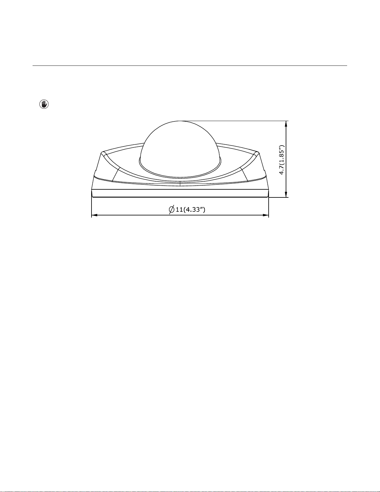
1.1 Dimensions
The dimension of the Sarix® Professional Series Rugged Environmental Wedge Dome camera is shown in the Figure 1-1
below.
VALUES IN PARENTHESES ARE INCHES; ALL OTHERS ARE
CENTIMETERS.
RUGGED ENVIRONMENTAL WEDGE DOME
FIGURE 1-1: PHYSICAL DIMENSIONS
7

1.2 Models Introduction
Model
Description
IWP121-1ES
1MP Rugged Environmental Wedge Dome Camera
IWP221-1ES
2MP Rugged Environmental Wedge Dome Camera
The physical appearances and installation methods for the models indicated within the list below are, by and large, the same.
Therefore, please use this manual where we use the example from IWP221-1ES as a reference to apply to all the models.
TABLE 1-1: MODELS LIST
8
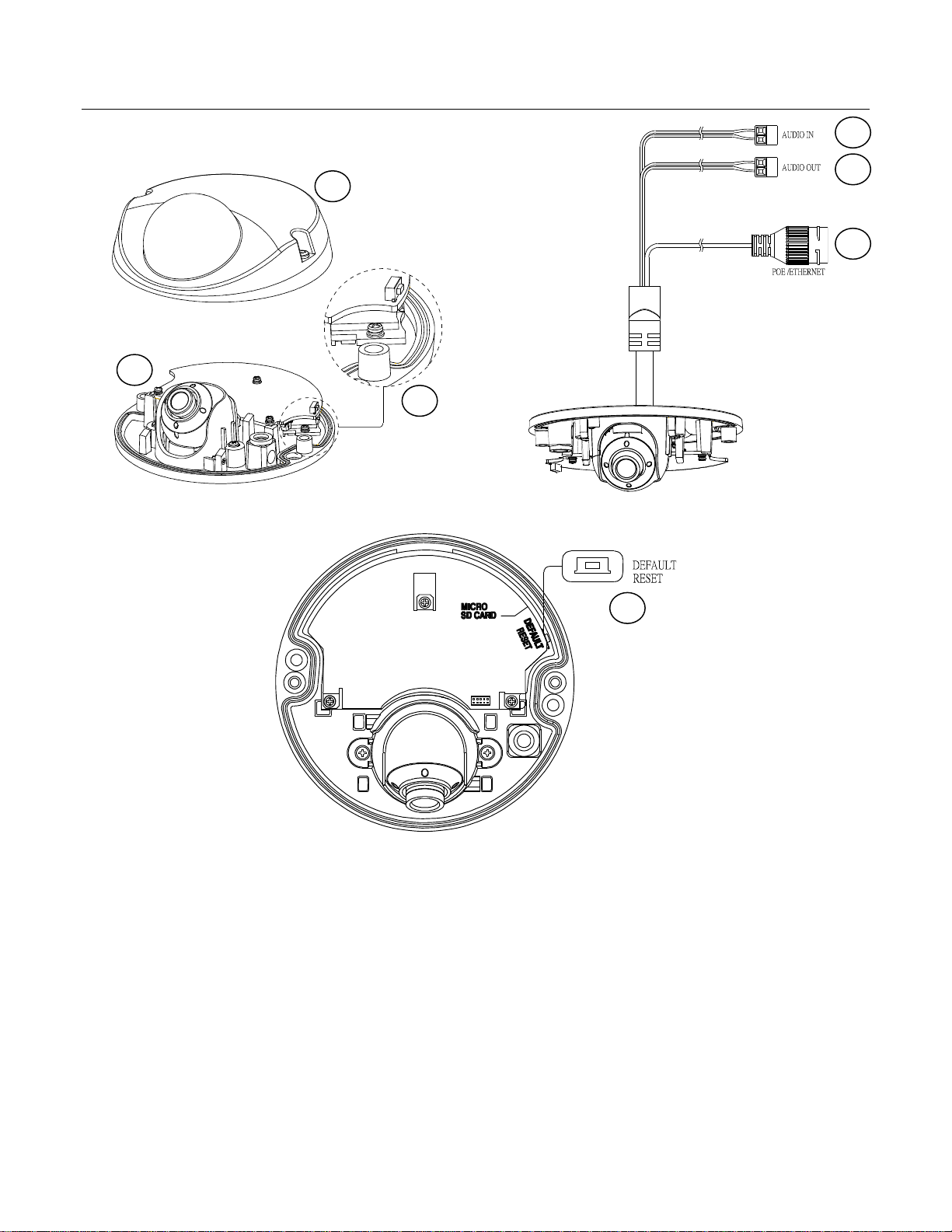
1.3 Physical Characteristics
1 2 3 4 6
7
5
FIGURE 1-2: CAMERA CONNECTIONS AND FEATURES 1/3 FIGURE 1-3: CAMERA CONNECTIONS AND FEATURES 2/3
FIGURE 1-4: CAMERA CONNECTIONS AND FEATURES 3/3
1. Dome Cover: The upper dome cover of the camera.
2. Camera Body: The physical main body of the camera.
3. Micro SD Card Slot: The slot is for inserting micro SD card for file storage.
4. Audio In: Connect to an external microphone. White port: Audio in; Black port: GND.
5. Audio Out: Connect to a speaker. Red port: Audio out; Black port: GND.
6. RJ-45 Network Port: Connect the RJ-45 connector to this port with a PoE compatible network device that
supplied power through the Ethernet cable.
7. Default & Reset Button:
Default: Press the button for 6 seconds to restore the camera’s settings back to the factory default.
Reset: Press the button for below 1 second to reboot the camera.
9

2. Installation and Connection
2.1 Unpacking Everything
Check all items in the product box against the order form and the packing slip. In addition to this manual, the items below are
included in the product box:
Fixed Flat Dome Camera * 1
Plastic Anchor * 2
Flat Head Screw (Tapping Type) * 2
Security Torx Wrench * 1
Mounting Template * 1
Printed Quick Installation Guide * 1
Resources sheet * 1
Desiccant * 1
Important Safety Instruction * 1
Please contact your dealer if any items are missing.
2.2 Installation
Following tools might help you complete the installation:
A drill
Screwdrivers
Wire cutters
2.2.1 Checking Appearance
Although the protective materials used for the packaging should be able to protect the unit from most accidents during
transportation, check the unit and its accessories for any visible damage. Remove the protective film to check items in
accordance with the list in 2.1 Unpacking Everything.
2.2.2 Connecting the Wires
Connect the PoE (IEEE 802.3af Class 0) port with a RJ-45 jack that links a PoE compatible network device that supplied
power with networking capability through the Ethernet cable.
Insert audio input/output cables to the connectors of unit if required.
NOTE: To avoid the length deficiency, it's suggested to reserve about 10mm length of the network cable for connecting
the cable to the RJ-45 network port before fix the cable to the cable slot.
10
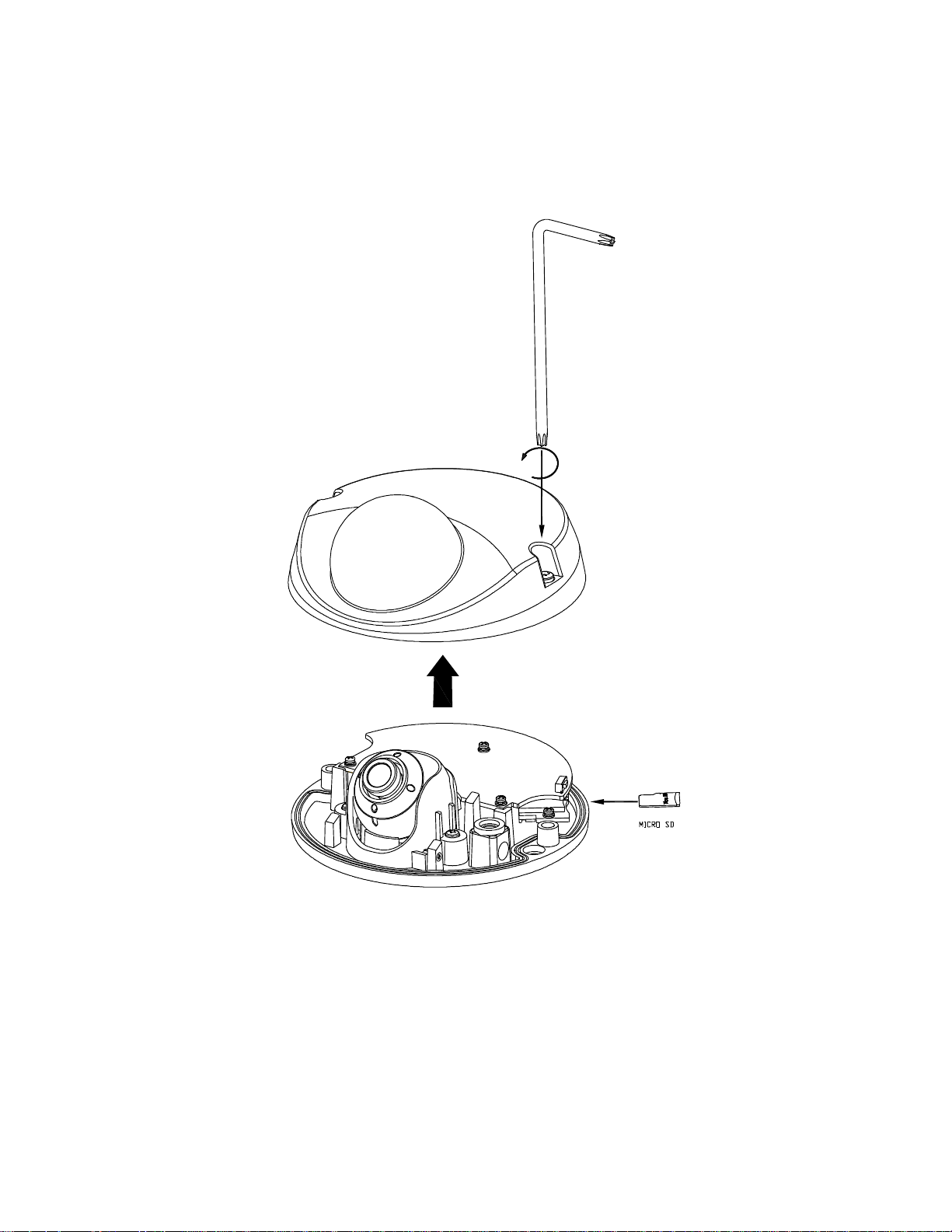
2.2.3 Disassembling the Camera
1. Loosen the 2 screws on the cover by the supplied torx wrench.
2. Remove the dome cover gently.
3. Insert the optional micro SD card for file storage if necessary.
FIGURE 2 - 1: DISASSEMBLING THE CAMERA
11
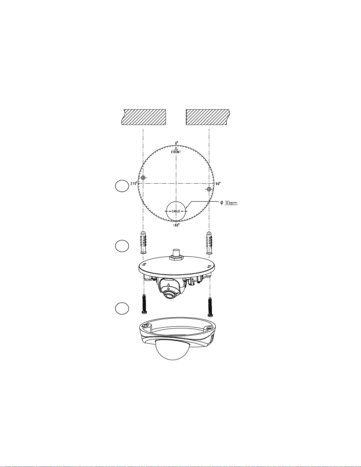
2.2.4 Installing the Camera
1. Mounting Template
2. Plastic Anchors x 2
3. Flat Head Screws
(Tapping Type) x 2
1
2
3
1. Attach the mounting template to the wall or ceiling.
2. Drill two holes indicated on the mounting surface and insert the plastic anchors into the holes.
3. Please drill another hole with Ø30mm in diameter as indicated on the mounting template in the wall or ceiling and pass
all the signal cables through the hole.
4. Secure the unit body to the wall or ceiling with the 2 flat head screws (tapping type).
12
FIGURE 2 - 2: INSTALLING THE CAMERA
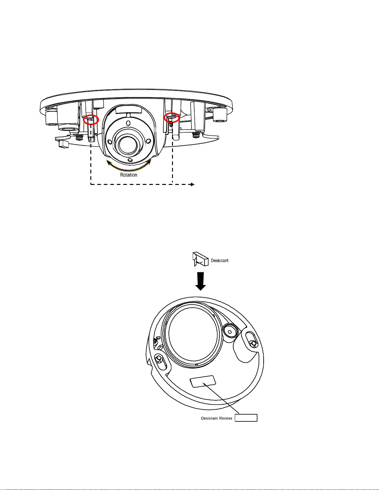
2.2.5 Adjusting the Camera Position
The lens can be adjusted vertically & horizontally
once the two screws are fully loosened.
1. Loosen the two screws beside the lens as figure shown below.
2. Adjust the lens to a desired shooting angle for suitable field of view.
NOTE: Make sure to relock the 2 screws tightly after adjustment.
FIGURE 2 - 3: ADJUSTING THE FOCUS POSITION
2.2.6 Sticking Desiccant
1. Take out the desiccant from the package.
2. Flip over the dome cover and stick desiccant to the rectangular recess as shown in the figure below.
13
FIGURE 2 - 4: STICKING DESICCANT
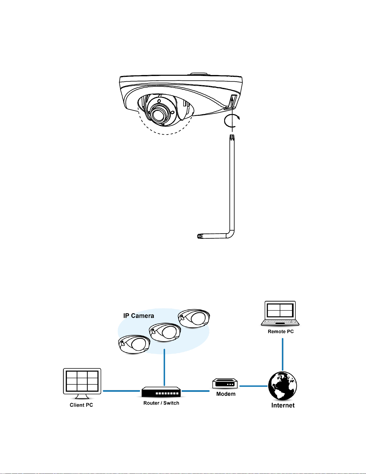
2.2.7 Completing the Installation
1. After mounting the unit body to the surface, attach the dome cover with extra care on direction.
2. Fasten the dome cover with unit body by securing screws tightly via torx wrench to complete installation.
FIGURE 2 - 5: COMPLETING THE INSTALLATION
2.2.8 Network Topology
The unit, which is equipped with Ethernet RJ-45 network interface, can deliver video images in real time via either Internet or
Intranet. Please refer to the skeleton drawings shown below to aid your understanding.
FIGURE 2-6: NETWORK TOPOLOGY
14

2.2.9 System Requirements
System Hardware
CPU
Intel® Pentium® 4 microprocessor, 2.4GHz or equivalent
RAM
1 GB or above
Monitor
Minimum of 1024 x 768 resolution, 16- or 32-bit pixel color resolution
System Software
Operating System
Microsoft Windows XP, Vista 32 and 64 bit, Win7 32 and 64 bit
Browser
Microsoft IE 8.0 and later
Media Player
Pelco Media Player or QuickTime® 7.6.5 for Windows XP, Windows Vista, and Windows 7; or
QuickTime 7.6.4 for Mac OS X 10.4 (or later)
Unit
Power Supply
PoE
Note
1. All the installation and operations should comply with your local electricity safety rules.
2. Pelco Media Player is recommended for control, smoothness, and reduced latency as compared to
QuickTime. The PMP is downloadable from Pelco web site: www.pelco.com/mediaplayer.
3. This product is not compatible with QuickTime version 7.6.4 for Windows XP or Windows Vista. If
you have this version installed on your PC, you will need to upgrade to QuickTime version 7.6.5.
4. Network and processor bandwidth limitations might cause the video stream to pause or appear
pixelated when additional Web-interface users connect to the camera. Decrease the images per
second (ips), resolution, compression, or bit rate settings of the Web interface video streams to
compensate for network or processor limitations.
The table below lists the minimum requirements to implement and operate a unit. Network and processor bandwidth limitations
might cause the video stream to pause or appear pixilated when additional Web-interface users connect to the camera.
Decrease the images per second (ips), resolution, compression, or bit rate settings of the Web interface video streams to
compensate for network/processor limitations.
TABLE 2-1: SYSTEM REQUIREMENTS
15

2.3 Connection
2.3.1 Default IP address
The unit’s default IP address is 192.168.0.20 and sub mask is 255.255.255.0. When setting default IP address of 192.168.0.20
the camera will check to see if that address is already in use and will bump the last octet of the address by 1 if it is. The bump
last octet of IP Address by 1 will continue until an unused IP address is found.
However, if you have a DHCP server in your network, the unit would obtain an IP address automatically from the DHCP server
so that you don’t need to change the camera’s IP address. The factory default is DHCP On and 192.168.0.20 assignment only
occurs when camera is set for DHCP but a DHCP server does not respond to request for an IP address.
2.3.2 Connecting From a Computer & Viewing Preparation
2.3.2.1 Using Pelco Device Utility Software to Get Camera’s IP Address
Pelco Device Utility software is a utility program that helps users to manage and configure the camera. Use the utility to find
the IP address since the default option is to obtain an IP address via DHCP and therefore the IP address will NOT be known.
Steps to get the utility program running are listed below.
1. Finish installing the Device Utility to the computer according to the installation instructions.
2. Log in to the Device Utility by entering the camera’s User name and Password. In the window, enter the default user
name: admin and password: admin, then click Enter button to log in.
3. In the Manage Devices page, you can click Refresh Device List or Add New Device to search for the devices.
4. From the Device List, you can get series information about camera, IP Address included.
For more information about using the Device Utility, click this green icon " " on the upper-right corner of the Device Utility
page.
2.4.2.2 Connecting from a computer
1. Check if there is the networking available between the unit and the computer by executing ping the default IP address.
Start a command prompt (Windows: from the Start Menu, select Program. Select Accessories and choose Command
Prompt.), and type “Ping 192.168.0.20”. If the message “Reply from…” appears, it means the connection is available.
2. Start Internet Explorer and enter IP address: 192.168.0.20. A login window should pop up. In the window, enter the
default user name: admin and password: admin to log in.
NOTE: If you do not know the camera’s IP address, you can locate it using the Pelco Device Utility software (refer to 2.4.2.1
Using Pelco Device Utility Software to Get Camera’s IP Address).
Further administration on the unit can be found in “3. Administration and Configuration".
FIGURE 2-7: LOGIN WINDOW
16

2.3.2.3 Viewing Preparation
Images of the unit can be viewed through Microsoft Internet Explorer 8 or later. Before viewing, follow these steps to enable
the display.
1. Enable Cookies On the Privacy tab, move the settings slider to Low or Accept All Cookies.
2. Change Security in Internet options and click Custom Level to open the Security Settings – Internet Zone screen.
NOTE: If the camera operates inside of the intranet, click the Intranet icon. If the camera operates outside of the intranet,
click the Internet icon.
3. Scroll down to the ActiveX controls and plug-ins radio buttons and set as follows:
【Download signed ActiveX controls】 Prompt (recommended)
【Download unsigned ActiveX controls】 Prompt
【Automatic prompting for ActiveX controls】 Enable
【Run ActiveX controls and plug-ins】 Enable
【Script ActiveX controls marked safe for scripting*】 Enable
4. Press OK to save the settings.
5. Close all Microsoft Internet Explorer Windows and restart a new window. This will allow the new settings taking effect.
6. Type your setting IP address into the browser.
7. Then you should be able to see the camera image screen.
17
3. Administration and Configuration
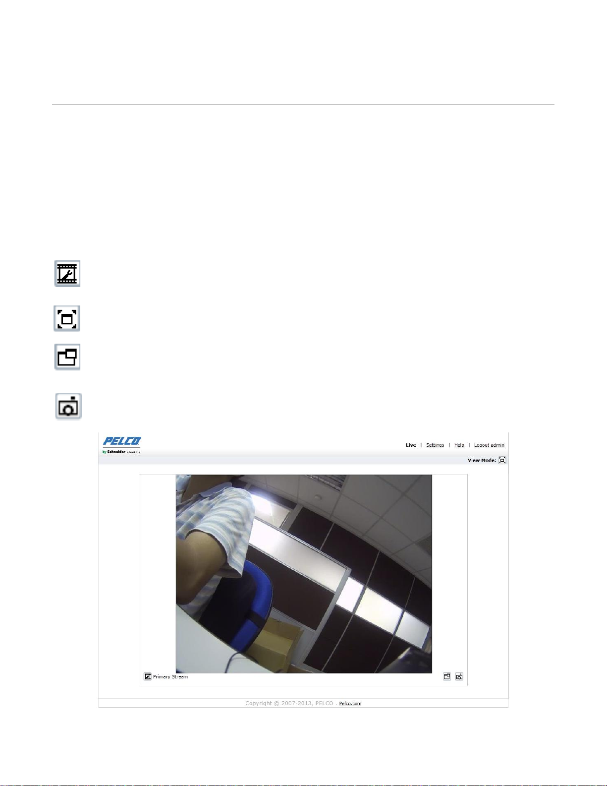
Select Stream: Selects the viewable video stream that is displayed in live view (primary, secondary or
quickview) and the transmission type (multicast or unicast) and the player type (Pelco Media Player and
Quicktime) all available for selection by user.
Maximize Viewing Area: Scales the image to the full size of the browser. To resize the video pane to normal
view, click the Show Toolbar button in the upper-right corner of the window.
Open Stream in New Window: Opens the video in a scalable, independent window. Opening the video in a
separate window allows you to view the video while other applications are running. This window can be
minimized, maximized, or closed using the title bar buttons of the active window. The window can also be
resized to your specifications by dragging the lower-right corner of the window.
Snapshot: Capture a screenshot of what is seen currently on the live view image. A prompt message appears,
after clicking the icon, to allow user to either open the screenshot or save the screenshot to a designated path.
3.1 Live
Simply click on Live on the top right side of the browser window while accessing the IP address of the unit, and a live video is
displayed directly in the browser window. When clicked on Settings, a window will pop up for configuring “System”,
“Network”, “Imaging”, “A/V Streams”, “Users”, and “Events”. Please refer to 3.2 Settings on page 19 for more information.
The current logged in identity shows to the right of the Help. Click on Logout admin of the administration window and
configuration will return to the camera image screen.
* Figures of 3. Administration and Configuration are taken from the 3MP model for web interface introduction purposes.
Options within each item may differ slightly among series products and the differences will be marked in a NOTE.
Followings are explanations of the options on the Live window.
18
FIGURE 3-1: LIVE VIEW
 Loading...