

Pelco IS51-CHV10F, IS50-CHV10F User Manual

INSTALLATION
IS50/IS51 Series Camclosure® 2 Integrated Camera System
Super Dynamic 5 (SD5)™, Day/Night,
and Color Models;
Flush Mount, Surface Mount
C3473M-C (10/10)

Contents
Important Safety Instructions. . . . . . . . . . . . . . . . . . . . . . . . . . . . . . . . . . . . . . . . . . . . . . . . . . . . . . . . . . . . . 5
UL Listed Models . . . . . . . . . . . . . . . . . . . . . . . . . . . . . . . . . . . . . . . . . . . . . . . . . . . . . . . . . . . . . . . . . 6
Warnings . . . . . . . . . . . . . . . . . . . . . . . . . . . . . . . . . . . . . . . . . . . . . . . . . . . . . . . . . . . . . . . . . . . . . . . 6
Regulatory Notices. . . . . . . . . . . . . . . . . . . . . . . . . . . . . . . . . . . . . . . . . . . . . . . . . . . . . . . . . . . . . . . . . . . . . 7
Precautions . . . . . . . . . . . . . . . . . . . . . . . . . . . . . . . . . . . . . . . . . . . . . . . . . . . . . . . . . . . . . . . . . . . . . . . . . . . 8
Flush Mount Installations Only: Additional Precautions . . . . . . . . . . . . . . . . . . . . . . . . . . . . . . . . . . 11
Limitation of Liability . . . . . . . . . . . . . . . . . . . . . . . . . . . . . . . . . . . . . . . . . . . . . . . . . . . . . . . . . . . . . . . . . . 12
Disclaimer of Warranty . . . . . . . . . . . . . . . . . . . . . . . . . . . . . . . . . . . . . . . . . . . . . . . . . . . . . . . . . . . . . . . . 12
Description . . . . . . . . . . . . . . . . . . . . . . . . . . . . . . . . . . . . . . . . . . . . . . . . . . . . . . . . . . . . . . . . . . . . . . . . . . 13
Models . . . . . . . . . . . . . . . . . . . . . . . . . . . . . . . . . . . . . . . . . . . . . . . . . . . . . . . . . . . . . . . . . . . . . . . . 13
Parts List. . . . . . . . . . . . . . . . . . . . . . . . . . . . . . . . . . . . . . . . . . . . . . . . . . . . . . . . . . . . . . . . . . . . . . . 14
Features of All Models. . . . . . . . . . . . . . . . . . . . . . . . . . . . . . . . . . . . . . . . . . . . . . . . . . . . . . . . . . . . 15
Features of the Super Dynamic 5 (SD5)™ Models. . . . . . . . . . . . . . . . . . . . . . . . . . . . . . . . . . . . . . . 15
Product Overview . . . . . . . . . . . . . . . . . . . . . . . . . . . . . . . . . . . . . . . . . . . . . . . . . . . . . . . . . . . . . . . . . . . . . 17
Super Dynamic 5 (SD5)™ Model . . . . . . . . . . . . . . . . . . . . . . . . . . . . . . . . . . . . . . . . . . . . . . . . . . . . 17
Day/Night and Color Models . . . . . . . . . . . . . . . . . . . . . . . . . . . . . . . . . . . . . . . . . . . . . . . . . . . . . . . 19
Installation . . . . . . . . . . . . . . . . . . . . . . . . . . . . . . . . . . . . . . . . . . . . . . . . . . . . . . . . . . . . . . . . . . . . . . . . . . 21
Using a 2-Gang Junction Box. . . . . . . . . . . . . . . . . . . . . . . . . . . . . . . . . . . . . . . . . . . . . . . . . . . . . . . 22
Surface Mounting. . . . . . . . . . . . . . . . . . . . . . . . . . . . . . . . . . . . . . . . . . . . . . . . . . . . . . . . . . . . . . . . 24
Flush Mounting. . . . . . . . . . . . . . . . . . . . . . . . . . . . . . . . . . . . . . . . . . . . . . . . . . . . . . . . . . . . . . . . . . 30
Adjusting the Camera: Super Dynamic 5 (SD5)™ Models. . . . . . . . . . . . . . . . . . . . . . . . . . . . . . . . . 37
Adjusting the Camera: Color and Day/Night Models . . . . . . . . . . . . . . . . . . . . . . . . . . . . . . . . . . . . 42
Removing the Heater . . . . . . . . . . . . . . . . . . . . . . . . . . . . . . . . . . . . . . . . . . . . . . . . . . . . . . . . . . . . . 44
Mounting the Enclosure and Inner Dome . . . . . . . . . . . . . . . . . . . . . . . . . . . . . . . . . . . . . . . . . . . . . 45
Wiring . . . . . . . . . . . . . . . . . . . . . . . . . . . . . . . . . . . . . . . . . . . . . . . . . . . . . . . . . . . . . . . . . . . . . . . . . . . . . . 47
Waterproof Treatment for the Cable Joint Sections . . . . . . . . . . . . . . . . . . . . . . . . . . . . . . . . . . . . . 47
Connecting Conduit . . . . . . . . . . . . . . . . . . . . . . . . . . . . . . . . . . . . . . . . . . . . . . . . . . . . . . . . . . . . . . 48
Connecting Wiring . . . . . . . . . . . . . . . . . . . . . . . . . . . . . . . . . . . . . . . . . . . . . . . . . . . . . . . . . . . . . . . 49
Video Output Connection . . . . . . . . . . . . . . . . . . . . . . . . . . . . . . . . . . . . . . . . . . . . . . . . . . . . . 49
Power Connection . . . . . . . . . . . . . . . . . . . . . . . . . . . . . . . . . . . . . . . . . . . . . . . . . . . . . . . . . . 50
Troubleshooting . . . . . . . . . . . . . . . . . . . . . . . . . . . . . . . . . . . . . . . . . . . . . . . . . . . . . . . . . . . . . . . . . . . . . . 51
Specifications. . . . . . . . . . . . . . . . . . . . . . . . . . . . . . . . . . . . . . . . . . . . . . . . . . . . . . . . . . . . . . . . . . . . . . . . 52
Super Dynamic 5 (SD5)™ Models . . . . . . . . . . . . . . . . . . . . . . . . . . . . . . . . . . . . . . . . . . . . . . . . . . . 52
Color and Day/Night Models . . . . . . . . . . . . . . . . . . . . . . . . . . . . . . . . . . . . . . . . . . . . . . . . . . . . . . . 55
2 C3473M-C (10/10)

List of Illustrations
1 Dehumidifying Device . . . . . . . . . . . . . . . . . . . . . . . . . . . . . . . . . . . . . . . . . . . . . . . . . . . . . . . . . . . . . 9
2 Screws on the Rear of the Camera . . . . . . . . . . . . . . . . . . . . . . . . . . . . . . . . . . . . . . . . . . . . . . . . . . 10
3 Super Dynamic 5 (SD5)™ . . . . . . . . . . . . . . . . . . . . . . . . . . . . . . . . . . . . . . . . . . . . . . . . . . . . . . . . . . 16
4 Super Dynamic 5 (SD5)™ Model Product Overview . . . . . . . . . . . . . . . . . . . . . . . . . . . . . . . . . . . . . 17
5 Day/Night and Color Model Product Overview . . . . . . . . . . . . . . . . . . . . . . . . . . . . . . . . . . . . . . . . . 19
6 Mounting the Camera Attachment to a 2-Gang Junction Box . . . . . . . . . . . . . . . . . . . . . . . . . . . . . 22
7 Mounting the Camera on a 2-Gang Junction Box . . . . . . . . . . . . . . . . . . . . . . . . . . . . . . . . . . . . . . . 23
8 Installing the Mounting Base. . . . . . . . . . . . . . . . . . . . . . . . . . . . . . . . . . . . . . . . . . . . . . . . . . . . . . . 24
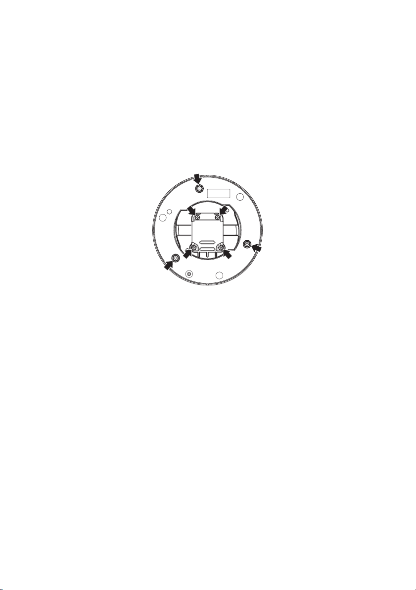
9 Mounting Holes . . . . . . . . . . . . . . . . . . . . . . . . . . . . . . . . . . . . . . . . . . . . . . . . . . . . . . . . . . . . . . . . . 25
10 Mounting the Camera Attachment to the Mounting Base . . . . . . . . . . . . . . . . . . . . . . . . . . . . . . . . 25
11 Routing the Cables. . . . . . . . . . . . . . . . . . . . . . . . . . . . . . . . . . . . . . . . . . . . . . . . . . . . . . . . . . . . . . . 26
12 Attaching the Camera to the Camera Attachment (Surface Mount) . . . . . . . . . . . . . . . . . . . . . . . . . 27
13 Securing the Camera to the Camera Attachment (Surface Mount). . . . . . . . . . . . . . . . . . . . . . . . . . 28
14 Making Cable Connections . . . . . . . . . . . . . . . . . . . . . . . . . . . . . . . . . . . . . . . . . . . . . . . . . . . . . . . . 28
15 Routing the Cables. . . . . . . . . . . . . . . . . . . . . . . . . . . . . . . . . . . . . . . . . . . . . . . . . . . . . . . . . . . . . . . 29
16 Installing the Base Cover . . . . . . . . . . . . . . . . . . . . . . . . . . . . . . . . . . . . . . . . . . . . . . . . . . . . . . . . . . 29
17 Tightening the Base Cover Fixing Screws . . . . . . . . . . . . . . . . . . . . . . . . . . . . . . . . . . . . . . . . . . . . . 30
18 Installing Flush Mount Models . . . . . . . . . . . . . . . . . . . . . . . . . . . . . . . . . . . . . . . . . . . . . . . . . . . . . 30
19 Installing the Anchor Bolts. . . . . . . . . . . . . . . . . . . . . . . . . . . . . . . . . . . . . . . . . . . . . . . . . . . . . . . . . 31
20 Mounting the Safety Wire Angle. . . . . . . . . . . . . . . . . . . . . . . . . . . . . . . . . . . . . . . . . . . . . . . . . . . . 32
21 Using Spacer Nuts . . . . . . . . . . . . . . . . . . . . . . . . . . . . . . . . . . . . . . . . . . . . . . . . . . . . . . . . . . . . . . . 32
22 Connecting the Mount Bracket to the Safety Wire . . . . . . . . . . . . . . . . . . . . . . . . . . . . . . . . . . . . . . 33
23 Installing the Mount Bracket . . . . . . . . . . . . . . . . . . . . . . . . . . . . . . . . . . . . . . . . . . . . . . . . . . . . . . . 33
24 Secure the Mount Bracket to the Ceiling. . . . . . . . . . . . . . . . . . . . . . . . . . . . . . . . . . . . . . . . . . . . . . 34
25 Attaching the Camera Attachment to the Camera Mount Bracket . . . . . . . . . . . . . . . . . . . . . . . . . . 35
26 Attaching the Camera to the Camera Attachment (Flush Mount) . . . . . . . . . . . . . . . . . . . . . . . . . . . 35
27 Securing the Camera to the Camera Attachment (Flush Mount). . . . . . . . . . . . . . . . . . . . . . . . . . . . 36
28 Attaching the Ceiling Mount Cover . . . . . . . . . . . . . . . . . . . . . . . . . . . . . . . . . . . . . . . . . . . . . . . . . . 36
29 Detaching the Inner Dome . . . . . . . . . . . . . . . . . . . . . . . . . . . . . . . . . . . . . . . . . . . . . . . . . . . . . . . . . 37
30 Tightening the Camera Fixing Screw . . . . . . . . . . . . . . . . . . . . . . . . . . . . . . . . . . . . . . . . . . . . . . . . . 38
31 Removing the Transport Protection Screw. . . . . . . . . . . . . . . . . . . . . . . . . . . . . . . . . . . . . . . . . . . . . 39
32 Adjusting the Camera Angle . . . . . . . . . . . . . . . . . . . . . . . . . . . . . . . . . . . . . . . . . . . . . . . . . . . . . . . 40
33 Adjusting the Focus . . . . . . . . . . . . . . . . . . . . . . . . . . . . . . . . . . . . . . . . . . . . . . . . . . . . . . . . . . . . . . 41
34 Focus Position Screen . . . . . . . . . . . . . . . . . . . . . . . . . . . . . . . . . . . . . . . . . . . . . . . . . . . . . . . . . . . . 41
35 Adjusting the Panning Position . . . . . . . . . . . . . . . . . . . . . . . . . . . . . . . . . . . . . . . . . . . . . . . . . . . . . 42
36 Adjusting the Tilting Position (Day/Night Model Shown) . . . . . . . . . . . . . . . . . . . . . . . . . . . . . . . . . 43
37 Adjusting the Azimuth Angle (Color Model Shown) . . . . . . . . . . . . . . . . . . . . . . . . . . . . . . . . . . . . . 43
38 Adjusting the Zoom and Focus . . . . . . . . . . . . . . . . . . . . . . . . . . . . . . . . . . . . . . . . . . . . . . . . . . . . . . 44
39 Removing the Heater . . . . . . . . . . . . . . . . . . . . . . . . . . . . . . . . . . . . . . . . . . . . . . . . . . . . . . . . . . . . . 45
40 Reattaching the Enclosure . . . . . . . . . . . . . . . . . . . . . . . . . . . . . . . . . . . . . . . . . . . . . . . . . . . . . . . . . 46
41 Using Butyl Tape to Waterproof Power Cable . . . . . . . . . . . . . . . . . . . . . . . . . . . . . . . . . . . . . . . . . . 47
42 Using Butyl Tape to Waterproof Video Output Cable . . . . . . . . . . . . . . . . . . . . . . . . . . . . . . . . . . . . 47
43 Using Conduit from the Bottom . . . . . . . . . . . . . . . . . . . . . . . . . . . . . . . . . . . . . . . . . . . . . . . . . . . . . 48
44 Using Conduit from the Top . . . . . . . . . . . . . . . . . . . . . . . . . . . . . . . . . . . . . . . . . . . . . . . . . . . . . . . . 48
45 Wiring Diagram . . . . . . . . . . . . . . . . . . . . . . . . . . . . . . . . . . . . . . . . . . . . . . . . . . . . . . . . . . . . . . . . . 49
C3473M-C (10/10) 3

List of Tables
A Recommended Mounting . . . . . . . . . . . . . . . . . . . . . . . . . . . . . . . . . . . . . . . . . . . . . . . . . . . . . . . . . . 21
B Maximum Extensible Cable Length . . . . . . . . . . . . . . . . . . . . . . . . . . . . . . . . . . . . . . . . . . . . . . . . . . 49
C Camera Power Cord Wire Colors and Functions . . . . . . . . . . . . . . . . . . . . . . . . . . . . . . . . . . . . . . . . 50
D 24 V AC Recommended Wire Gauge . . . . . . . . . . . . . . . . . . . . . . . . . . . . . . . . . . . . . . . . . . . . . . . . . 50
E 12 V DC Recommended Wire Size and Resistance (68 °F [20 °C]) . . . . . . . . . . . . . . . . . . . . . . . . . . 50
F Troubleshooting the IS50/IS51 Series . . . . . . . . . . . . . . . . . . . . . . . . . . . . . . . . . . . . . . . . . . . . . . . . 51
4 C3473M-C (10/10)
Important Safety Instructions
1. Read these instructions.
2. Keep these instructions.
3. Heed all warnings.
4. Follow all instructions.
5. Clean only with dry cloth.
6. Do not block any ventilation openings. Install in accordance with the manufacturer's instructions.
7. Do not install near any heat sources such as radiators, heat registers, stoves, or other apparatus (including
amplifiers) that produce heat.
8. Do not defeat the safety purpose of the polarized or grounding-type plug. A polarized plug has two blades
with one wider than the other. A grounding type plug has two blades and a third grounding prong. The wide
blade or the third prong are provided for your safety. If the provided plug does not fit into your outlet, consult
an electrician for replacement of the obsolete outlet.
9. Protect the power cord from being walked on or pinched particularly at plugs, convenience receptacles, and
the point where they exit from the apparatus.
10. Only use attachments/accessories specified by the manufacturer.
11. Use only with the cart, stand, tripod, bracket, or table specified by the manufacturer, or sold with the
apparatus. When a cart is used, use caution when moving the cart/apparatus combination to avoid injury
from tip-over.
S3125A
12. Unplug this apparatus during lightning storms or when unused for long periods of time.
The product and/or manual may bear the following marks:
The lightning flash with arrowhead symbol, within an
equilateral triangle, is intended to alert the user to the
presence of uninsulated “dangerous voltage” within the
product’s enclosure that may be of sufficient magnitude to
constitute a risk of electric shock to persons.
The exclamation point within an equilateral triangle is
intended to alert the user to the presence of important operating and maintenance (servicing) instructions
in the literature accompanying the appliance.
CAUTION: TO REDUCE THE RISK OF ELECTRIC SHOCK, DO NOT REMOVE COVER (OR BACK). NO USERSERVICEABLE PARTS INSIDE. REFER SERVICING TO QUALIFIED SERVICE PERSONNEL.
CAUTION:
RISK OF ELECTRIC SHOCK.
DO NOT OPEN.
C3473M-C (10/10) 5

UL LISTED MODELS
IS51-DWSV8S
IS51-DWSV8F
IS50-DWSV8S
IS50-DWSV8F
IS51-DNV10S
IS51-DNV10F
IS50-DNV10S
IS50-DNV10F
IS51-CHV10S
IS51-CHV10F
IS50-CHV10S
IS50-CHV10F
WARNINGS
• This apparatus must be earthed.
• This apparatus shall be connected to a mains socket outlet with a protective earthing connection.
• The mains plug or an appliance coupler shall remain readily operable.
• All work related to the installation of this product should be made by qualified service personnel or system
installers.
• The connections should comply with local electrical code.
6 C3473M-C (10/10)

We declare under our sole responsibility that the product to which this declaration relates is in conformity with the
standards or other normative documents following the provisions of Directives 2006/95/EC and 2004/108/EC.
Wij verklaren als enige aansprakelijke, dat het product waarop deze verklaring betrekking heeft, voldoet aan de
volgende normen of andere normatieve documenten, overeenkomstig de bepalingen van Richtlijnen 2006/95/EC en
2004/108/EC.
Vi erklærer os eneansvarlige for, at dette produkt, som denne deklaration omhandler, er i overensstemmelse med
standarder eller andre normative dokumenter i følge bestemmelserne i direktivene 2006/95/EC og 2004/108/EC.
Vi deklarerar härmed värt fulla ansvar för att den produkt till vilken denna deklaration hänvisar är i
överensstämmelse med standarddokument, eller andra normativa dokument som framstölls i direktiv nr. 2006/95/
EC och 2004/108/EC.
Ilmoitamme yksinomaisella vastuullamme, että tuote, jota tämä ilmoitus koskee, noudattaa seuraavia standardeja
tai muita ohjeellisia asiakirjoja, jotka noudattavat direktiivien 2006/95/EC ja 2004/108/EC säädöksiä.
Vi erklærer oss alene ansvarlige for at produktet som denne erklæringen gjelder for, er i overensstemmelse med
følgende normer eller andre normgivende dokumenter som følger bestemmelsene i direktivene 2006/95/EC og
2004/108/EC.
Wir erklären in alleiniger Verantwortung, daß das Produkt, auf das sich diese Erklärung bezieht, mit den folgenden
Normen oder normativen Dokumenten übereinstimmt. Gemäß den Bestimmungen der Richtlinie 2006/95/EC und
2004/108/EC.
Nous déclarons sous notre propre responsabilité que le produit auquel se réfère la présente déclaration est
conforme aux normes spécifiées ou à tout autre document normatif conformément aux dispositions des directives
2006/95/CE et 2004/108/CE.
Nosotros declaramos bajo nuestra única responsabilidad que el producto a que hace referencia esta declaración
está conforme con las normas u otros documentos normativos siguiendo las estipulaciones de las directivas 2006/
95/CE y 2004/108/CE.
Noi dichiariamo sotto nostra esclusiva responsabilità che il prodotto a cui si riferisce la presente dichiarazione
risulta conforme ai seguenti standard o altri documenti normativi conformi alle disposizioni delle direttive 2006/95/
CE e 2004/108/CE.
Regulatory Notices
This device complies with Part 15 of the FCC Rules. Operation is subject to the following two conditions: (1) this
device may not cause harmful interference, and (2) this device must accept any interference received, including
interference that may cause undesired operation.
RADIO AND TELEVISION INTERFERENCE
This equipment has been tested and found to comply with the limits of a Class A digital device, pursuant to Part 15
of the FCC rules. These limits are designed to provide reasonable protection against harmful interference when the
equipment is operated in a commercial environment. This equipment generates, uses, and can radiate radio
frequency energy and, if not installed and used in accordance with the instruction manual, may cause harmful
interference to radio communications. Operation of this equipment in a residential area is likely to cause harmful
interference in which case the user will be required to correct the interference at his own expense.
Changes and Modifications not expressly approved by the manufacturer or registrant of this equipment can void
your authority to operate this equipment under Federal Communications Commission’s rules.
In order to maintain compliance with FCC regulations shielded cables must be used with this equipment. Operation
with non-approved equipment or unshielded cables is likely to result in interference to radio and television
reception.
This Class A digital apparatus complies with Canadian ICES-003.
Cet appareil numérique de la classe A est conforme à la norme NMB-003 du Canada.
C3473M-C (10/10) 7

Precautions
1. Refer installation work to the dealer. Installation work requires technique and experience; otherwise, injury
or damage to the product may result. Be sure to consult the dealer.
2. Do not insert objects inside the product. If water or metallic items enter the product, it may cause fire or
electric shock. Turn the power off immediately and contact qualified service personnel for service.
3. Do not attempt to disassemble or modify the product. Failure to observe this may cause fire or electric shock.
Consult the dealer for the repair or inspections.
4. Stop operation immediately when something is wrong with the product. If smoke or the smell of smoke
comes from the product, continued use will result in fire, injury, or damage to the product. Turn the power off
immediately and contact qualified service personnel for service.
5. Select an installation area that can support the total weight. Selecting an inappropriate installation surface
may cause the product to fall down or topple over, resulting in injury. Installation work shall be started after
sufficient reinforcement.
6. Periodic inspections shall be conducted. Rust on the metal parts or screws may cause the product to fall
down resulting in injury. Consult the dealer for the inspections.
7. This product shall be installed in a vibration-free location. Failure to observe this may cause screws and bolts
to be loosened and consequently to fall resulting in injury.
8. Install this product high enough to ensure that people do not hit their heads. Failure to observe this may
cause a drop resulting in injury or accidents.
9. Do not strike or give a strong shock to this product. Failure to observe this may cause injury or fire.
10. Be sure to turn off the power before wiring. Failure to observe this may cause electric shock. A short circuit
or wrong wiring may cause fire.
11. Do not use the product in an atmosphere of flammable gases. Failure to observe this may cause injury by
explosion.
12. Avoid installing the product in locations where it is subject to damage by salt or corrosive gas; otherwise, the
mounting fixtures will deteriorate, causing the product to fall down resulting in injury.
13. Use the specified mounting bracket. Failure to observe this may cause the product to fall down resulting in
injury.
14. Do not rub the edges of metal parts with your hand. Failure to observe this may cause injury.
15. Tighten screws and mounting fixtures to the specified torque. Failure to observe this may cause a drop
resulting in injury or accidents.
16. This product has no power switch. Turn the power off when cleaning the product.
17. Parts of this product may deteriorate and it may shorten the lifetime of this product when used in locations
subject to high temperatures and high humidity. (Recommended operating temperature: +35 °C [95 °F] or
lower). Do not expose this product to direct heat sources such as a heater.
18. Handle this product with care. Do not abuse this product. Avoid striking, shaking, and so forth. The product
could be damaged by improper handling or storage. If a strong shock or vibration is applied to the enclosure,
it may cause damage or allow water to enter this product.
19. Do not touch the dome cover with your bare hands. A dirty dome cover causes deterioration of picture quality.
20. When continuously viewing a bright light source such as a spotlight, the color filter of the CCD may have
deteriorated and it may cause discoloration. Even when changing the fixed viewing direction after
continuously viewing a spotlight for a certain period, the discoloration may remain.
21. Do not aim this product at strong light sources. A light source such as a spot light causes a blooming (light
bleeding) or a smear (vertical lines).
8 C3473M-C (10/10)
22. Turn the power off when cleaning the product. Do not use strong abrasive detergent when cleaning this
product as this may cause discoloration. When using a chemical cloth for cleaning, read the caution provided
with the chemical cloth product.
23. When dirt is hard to remove, use a mild detergent and wipe gently. Then, wipe off the remaining detergent
with a dry cloth.
24. If OVER HEAT appears on the display, the inside of the camera has become extremely hot. Immediately turn
off the power of the camera and contact your dealer.
25. (Applies to Super Dynamic 5 (SD5)™ models only.) This product has a dehumidifying device to keep the inside
at a low moisture level, preventing condensation. Dew may be produced depending on the conditions of
temperature, humidity, winds, and rain, and it may take time to dehumidify. Never seal the surfaces of the
dehumidifying device.
Figure 1. Dehumidifying Device
ì
Dehumidifying Device
26. Installation work shall be performed in accordance with the technology standard of the electric installation.
27. The product is designed to be installed under eaves. Keep the product out of direct sunlight.
28. Contact your dealer for assistance if you are unsure of an appropriate site in your particular environment.
Make sure that the installation area is strong enough to hold the product, such as a concrete ceiling. Install
the camera in the foundation area of the architecture or where sufficient strength is assured. If a ceiling
board, such as plaster board, is too weak to support the total weight, the area shall be sufficiently reinforced.
29. Avoid installing this product in the following locations:
• Locations where a chemical agent is used such as a swimming pool (indoor and outdoor).
• Locations subject to steam and oil smoke such as a kitchen.
• Locations near flammable gas or vapor.
• Locations where radiation or x-ray emissions are produced.
• Locations where corrosive gas is produced, Locations where it may be damaged by briny air such as
seashores.
• Locations where the temperature is not within –10 °C to 50 °C (14 °F to 122 °F). When using the
heater unit, the product can be used at temperatures within –30 °C to 50 °C (–22 °F to 122 °F) and
humidity below 90%.
• Locations subject to vibrations. (This product is not designed for on-vehicle use.)
30. Avoid installing this system in moist or dusty places; otherwise, the lifetime of the internal parts may be
shortened.
31. Avoid installing the camera in a location with a high level of noise. Installation near an air conditioner, an air
cleaner, a vending machine, or the like causes noise.
32. Be sure to remove this product if it is not in use.
33. Keep the camera cable away from the lighting cable. Failure to observe this may cause noise.
C3473M-C (10/10) 9
34. When the camera is used near a TV/radio antenna, strong electric field, or magnetic field (near a motor or a
transformer), images may be distorted and audible noise may be produced. In such a case, route the camera
cable through specialized steel conduit tubes.
35. Screws are not supplied with this product and must be locally procured. Prepare the screws according to the
material, structure, strength and other factors of the mounting area and the total weight of objects to be
mounted.
36. The mounting screws and bolts must be tightened with an appropriate tightening torque according to the
material and strength of the installation area. Do not use an impact driver. Failure to observe this may cause
overtightening and damage to the screws. When a screw is tightened, position the screw at a right angle to
the surface. After tightening the screws or bolts, perform a visual check to ensure adequate tightening and
there is no backlash.
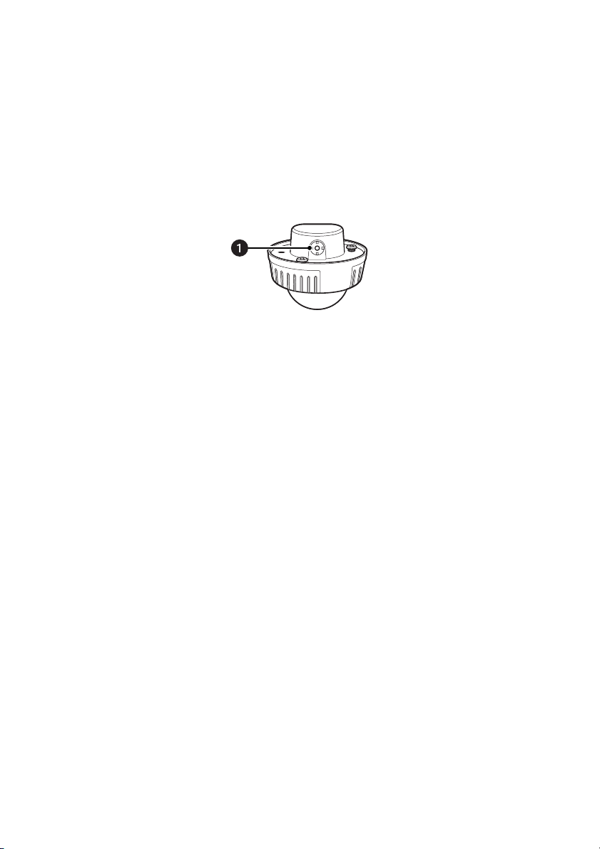
37. Do not remove or loosen any of the seven screws on the rear of the camera; otherwise, water exposure may
cause damage or malfunction of the camera, or it may cause the camera to drop resulting in injury.
Figure 2. Screws on the Rear of the Camera
10 C3473M-C (10/10)

FLUSH MOUNT INSTALLATIONS ONLY: ADDITIONAL PRECAUTIONS
(Recommended for indoor installations only)
1. Select a strong ceiling area. Make sure that the installation area is strong enough to hold the total weight of
the camera assembly before installation.
2. The installation area shall have 210 mm (8.25 inches) or more space behind the ceiling.
3. The thickness of the ceiling board for installation can range from 9 to 40 mm (0.38 to 1.56 inches).
4. Avoid installing in the following locations.
• Locations where it may get wet from rain or water splash
• Locations where a chemical agent is used such as a swimming pool (indoor and outdoor)
• Locations subject to steam and oil smoke such as a kitchen
• Locations where radiation or x-ray emissions are produced
• Locations where it may be damaged by briny air such as seashores
• Locations where the temperature is not within –30 °C to +50 °C (–22 °F to 122 °F).
• Locations subject to vibrations. (This product is not designed for on-vehicle use.)
• Locations where the temperature may rapidly change such as the peripheral areas of the air outlets of
air conditioners or doors facing outside. (If a camera is installed in such a location, the dome cover may
become foggy or condensation may occur on the cover.)
5. The screws and bolts must be tightened with an appropriate tightening torque according to the material and
strength of the installation area. After tightening the screws or bolts, perform a visual check to ensure
adequate tightening and there is no backlash. Required pullout capacity of a single screw/bolt is
196 N (44.1 lbf) or more.
6. Do not rub the edges of metal parts with your hand. Failure to observe this may cause injury.
7. Be sure to remove this apparatus if it is not in use.
8. Be sure to install the safety wire.
9. Periodic inspections shall be conducted. Rust on the metal parts or screws may cause the product to fall,
resulting in injury.
C3473M-C (10/10) 11

Limitation of Liability
THIS PUBLICATION IS PROVIDED “AS IS” WITHOUT WARRANTY OF ANY KIND, EITHER EXPRESS OR IMPLIED,
INCLUDING BUT NOT LIMITED TO, THE IMPLIED WARRANTIES OF MERCHANTABILITY, FITNESS FOR ANY
PARTICULAR PURPOSE, OR NON-INFRINGEMENT OF THE THIRD PARTY’S RIGHT.
THIS PUBLICATION COULD INCLUDE TECHNICAL INACCURACIES OR TYPOGRAPHICAL ERRORS.
CHANGES ARE ADDED TO THE INFORMATION HEREIN, AT ANY TIME, FOR THE IMPROVEMENTS OF THIS
PUBLICATION AND/OR THE CORRESPONDING PRODUCT (S).
Disclaimer of Warranty
IN NO EVENT SHALL PELCO BE LIABLE TO ANY PARTY OR ANY PERSON, EXCEPT FOR REPLACEMENT OR
REASONABLE MAINTENANCE OF THE PRODUCT, FOR THE CASES, INCLUDING BUT NOT LIMITED TO BELOW:
1. ANY DAMAGE AND LOSS, INCLUDING WITHOUT LIMITATION, DIRECT OR INDIRECT, SPECIAL,
CONSEQUENTIAL OR EXEMPLARY, ARISING OUT OF OR RELATING TO THE PRODUCT;
2. PERSONAL INJURY OR ANY DAMAGE CAUSED BY INAPPROPRIATE USE OR NEGLIGENT OPERATION OF THE
USER;
3. UNAUTHORIZED DISASSEMBLE, REPAIR OR MODIFICATION OF THE PRODUCT BY THE USER;
4. INCONVENIENCE OR ANY LOSS ARISING WHEN IMAGES ARE NOT DISPLAYED, DUE TO ANY REASON OR
CAUSE INCLUDING ANY FAILURE OR PROBLEM OF THE PRODUCT;
5. ANY PROBLEM, CONSEQUENTIAL INCONVENIENCE, OR LOSS OR DAMAGE, ARISING OUT OF THE SYSTEM
COMBINED BY THE DEVICES OF THIRD PARTY.
12 C3473M-C (10/10)

Description
The IS50/IS51 Series Camclosure® 2 Camera System integrates a camera and lens package into a small versatile
rugged enclosure that can be mounted directly to, or recessed into, a ceiling or wall. The IS50/IS51 Series features
a three-axis camera and lens positioning system that is capable of a wide variety of pan and tilt angles.
The IS50/IS51 Series offers three high resolution camera options suitable for a variety of outdoor environments:
Super Dynamic 5 (SD5)
The Super Dynamic 5 (SD5)
and auto back focus. Application examples include environments that require extremely high sensitivity and motion
detection.
Day/night models feature a high resolution (540 TVL) color camera with auto iris and varifocal lens. Application
examples include environments that require monochrome images at night and color images during the day.
Color models feature a high resolution (540 TVL) color camera with auto iris and varifocal lens. Application
examples include all general-purpose environments.
MODELS
IS51-DWSV8S
IS51-DWSV8F
IS50-DWSV8S
IS50-DWSV8F
IS51-DNV10S Day/Night, clear dome, surface mount, NTSC
IS51-DNV10F Day/Night, clear dome, flush mount, NTSC
IS50-DNV10S Day/Night, smoked dome, surface mount, NTSC
IS50-DNV10F Day/Night, smoked dome, flush mount, NTSC
IS51-CHV10S Color, clear dome, surface mount, NTSC
IS51-CHV10F Color, clear dome, flush mount, NTSC
IS50-CHV10S Color, smoked dome, surface mount, NTSC
IS50-CHV10F Color, smoked dome, flush mount, NTSC
IS51-DWSV8SX
IS51-DWSV8FX
IS50-DWSV8SX
IS50-DWSV8FX
IS51-DNV10S Day/Night, clear dome, surface mount, PAL
IS51-DNV10F Day/Night, clear dome, flush mount, PAL
IS50-DNV10S Day/Night, smoked dome, surface mount, PAL
IS50-DNV10F Day/Night, smoked dome, flush mount, PAL
IS51-CHV10S Color, clear dome, surface mount, PAL
IS51-CHV10F Color, clear dome, flush mount, PAL
IS50-CHV10S Color, smoked dome, surface mount, PAL
IS50-CHV10F Color, smoked dome, flush mount, PAL
™
day/night wide dynamic range (WDR), Day/night, and Color.
™
models feature a high resolution (650 TVL) color camera with auto iris, varifocal lens,
™
Super Dynamic 5 (SD5)
Super Dynamic 5 (SD5)
Super Dynamic 5 (SD5)
Super Dynamic 5 (SD5)
Super Dynamic 5 (SD5)
Super Dynamic 5 (SD5)
Super Dynamic 5 (SD5)
Super Dynamic 5 (SD5)
, clear dome, surface mount, NTSC
™
, clear dome, flush mount, NTSC
™
, smoked dome, surface mount, NTSC
™
, smoked dome, flush mount, NTSC
™
, clear dome, surface mount, PAL
™
, clear dome, flush mount, PAL
™
, smoked dome, surface mount, PAL
™
, smoked dome, flush mount, PAL
C3473M-C (10/10) 13

PARTS LIST
The following parts are supplied:
SURFACE MODELS
Qty Description
1 Camera module
1 Camera attachment
5 Phillips screws
1 Mounting base and base cover
1 Bit for tamperproof screw
1 Butyl tape
1 Installation manual
1 Operation manual (CD-ROM)
FLUSH MODELS
(Recommended for indoor installations only)
Qty Description
1 Camera module
1 Camera attachment
5 Phillips screws
1 Flush mount kit
1 Ceiling mount bracket
1 Safety wire
1 Safety wire angle
1 Template A
1 Template B
1 Ceiling mount cover
1 Bit for tamperproof screw
1 Butyl tape
1 Installation manual
1 Operation manual (CD-ROM)
14 C3473M-C (10/10)

FEATURES OF ALL MODELS
Adaptive Black Stretch
Adaptive black stretch technology increases the visibility of subjects in dark areas of a video scene without
degrading image quality in the brighter areas. This is accomplished by analyzing the illumination map/signal level
distribution and adjusting the gamma correction for each area separately. This results in clear, more visible images.
Factory-Installed Heater for Outdoor Installations
The heater turns on automatically when the temperature inside the camera drops below +10 °C (50 °F) and turns
off when the temperature rises. A small fan inside the heater minimizes condensation on the surface of the
enclosure caused by changes in ambient temperature unless temperatures change too rapidly.
NOTES:
• When using a 12 V DC power supply, the heater is unavailable.
• Turning the heater on and off may disturb the camera images.
• The power supply of the camera shall be turned off when mounting or dismounting the heater.
• When servicing, pay attention to high temperatures on the surface of the heater. Disconnect the harness and
wait until the heater cools.
• When the camera is installed and operated in low temperatures below –10 °C (14 °F), normal images may
not be obtained immediately after startup. In such a case, wait approximately 60 minutes or more.
FEATURES OF THE SUPER DYNAMIC 5 (SD5)™ MODELS
High Resolution CCD
The new CCD has 976 horizontal pixels and a horizontal resolution as high as 650 TV lines (typ.).
Auto Back Focus (ABF)
Automatically adjust the back focus using the operation button or the setup menu.
The auto back focus function also allows users to correct the focus when changing between color and black-white
images.
High Sensitivity with Noise Reduction
The introduction of low noise circuit design has achieved extremely high sensitivity, resulting in the minimum
illuminance of 0.1 lux in the color mode and 0.01 lux in the black-white mode.
Night Monochrome Image Activation
No operation is required at night because the image automatically changes from the color mode to the black-white
mode at low illuminance.
C3473M-C (10/10) 15
Intelligent VMD (i-VMD): Motion Detection, Object Abandonment/Removal
Detection, and Scene Change Detection
The intelligent motion detection function allows he camera to detect motion of an object, appearance or
disappearance of an object, or interference with the camera. When one of these types of motion is detected, a
frame is displayed on the screen.
Scene change detection provides an alert if interference with the camera is detected. For example, if the camera is
covered with a cloth or a cap, or if the direction of the camera is changed.
NOTE: The i-VMD is not an infallible method of preventing thefts, fires, and so forth. Pelco is not responsible for
any accidents or damages occurring in these instances.
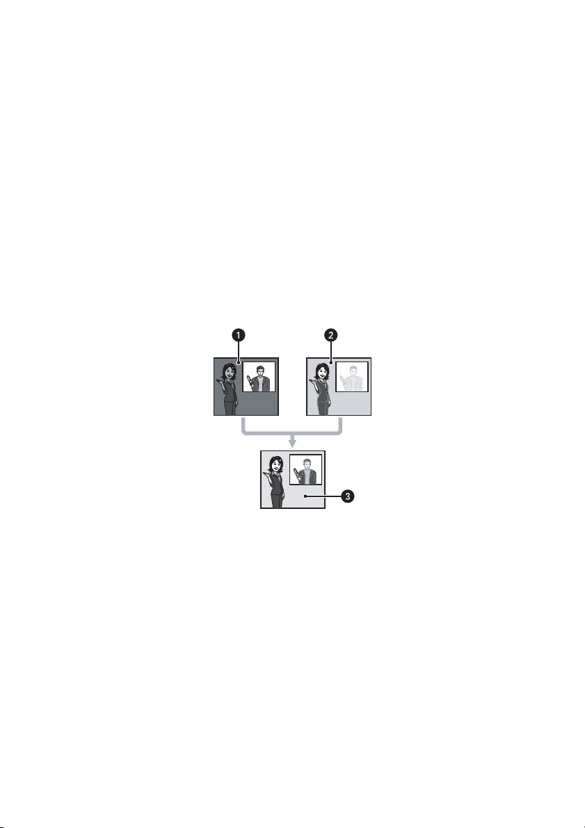
Super Dynamic 5 (SD5)
Integration of Super Dynamic 5 (SD5)™ * into the CCD and signal processing circuit has achieved approximately
128 times higher dynamic range compared to conventional cameras.
In scenes with high contrast between the bright and dark areas, the dark areas become less visible because the
camera adjusts the iris in accordance with the bright areas. Conversely, adjusting the lens brightness for the darker
areas causes the brighter areas to become washed out.
The Super Dynamic 5 (SD5)
image that is configured for darker areas, creating a final image that preserves overall detail.
ì
î
ï
™
™
function digitally combines an image that is configured for brighter areas with an
Figure 3. Super Dynamic 5 (SD5)
The Subject in the Dark Area is Hard to Notice
The Subject in the Light Area is Hard to Notice
A Clearer Image is Created by Digitally Combining Images
™
*The Super Dynamic 5 (SD5)™ logo is a registered trademark of Panasonic Corporation in the United States and/or
other countries.
16 C3473M-C (10/10)
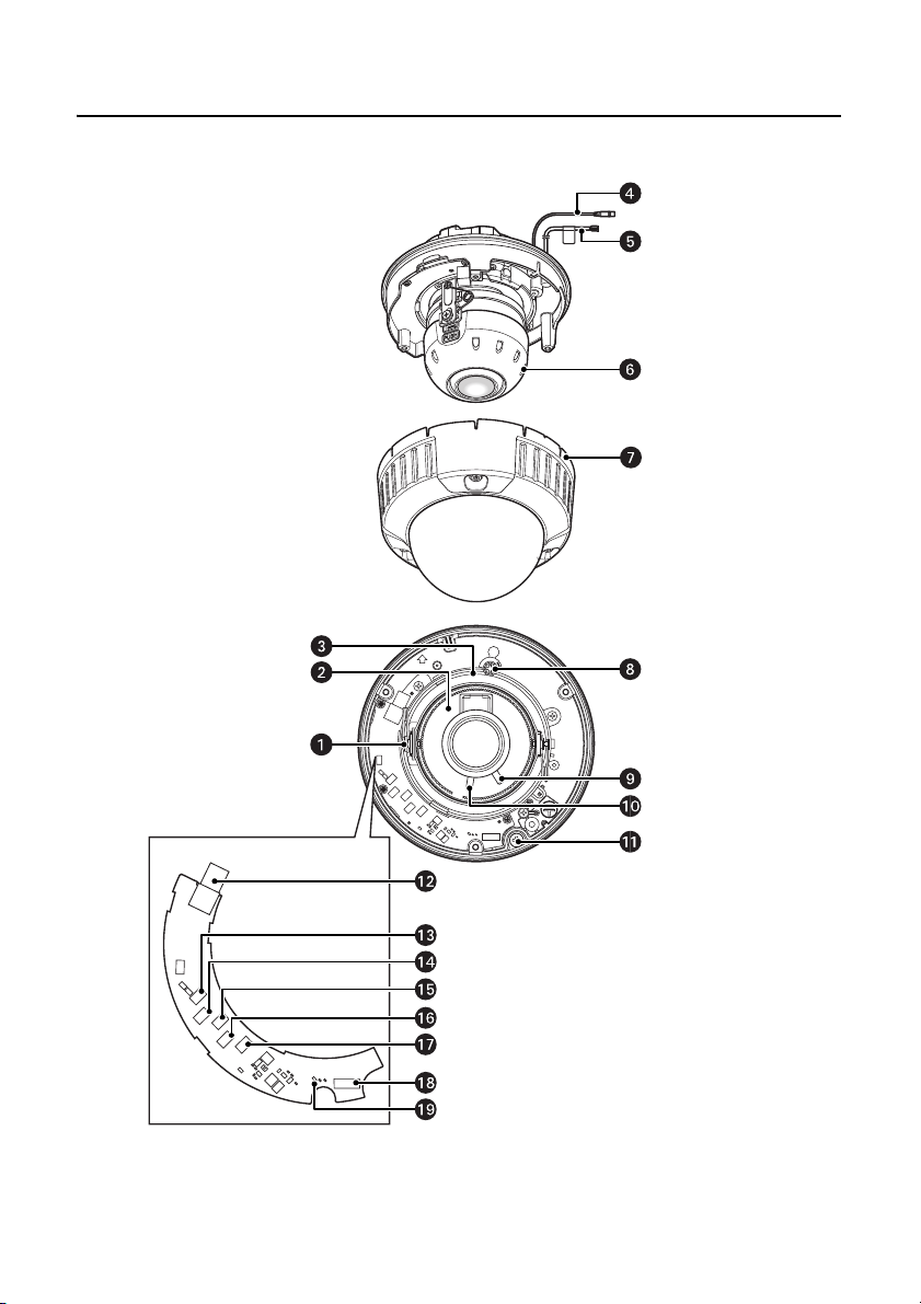
Product Overview
SUPER DYNAMIC 5 (SD5)™ MODEL
Figure 4. Super Dynamic 5 (SD5)™ Model Product Overview
C3473M-C (10/10) 17

ì
Tilting Lock Screw: Locks the tilt position.
î
Tilt Adjusting Table: Adjust the azimuth angle of the image.
ï
Panning Table: Rotate this table to adjust the panning angle of the camera.
ñ
Video Output Cable
ó
Power Cord
r
Inner Dome
s
Enclosure
t
Panning Lock Screw: Fixes the panning table.
u
Focus Lock Knob: Locks the focal point.
~í
Zoom Lock Knob: Locks the zoom point.
~â
Camera Fixing Screw: Fixes the attachment on the camera body.
~ä
Monitor Output Connector: Connects the monitor for adjustment to this output connector.
~ã
Right Button [(RIGHT), FAR]: Moves the cursor to the right, selects the mode and adjusts some levels.
~å
Left Button [(LEFT), NEAR]: Moves the cursor to the left, selects the mode and adjusts some levels.
~ç
Up Button [(UP)]: Moves the cursor upward and selects items in the setup menu.
~é
Down Button [(DOWN), ABF1]: Moves the cursor downward and selects items in the setup menu.
~è
Setting Button [(SET), ABF2/MENU]: Confirms the setting contents.
~ê
Heater Output Connector: Connects to the heater unit.
~ë
ABF Operation Indicator: Indicates the status of ABF operation.
18 C3473M-C (10/10)
 Loading...