

Page 1
INSTALLATION
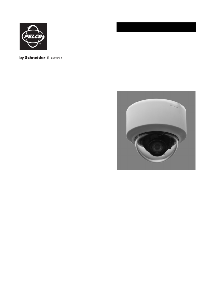
IS20/IS21-DWS Series Camclosure® 2 Integrated Camera System
Super Dynamic 5 (SD5)™ Models
Flush Mount, Surface Mount
C3475M-A (10/10)
Page 2

Page 3

Contents
Important Safety Instructions. . . . . . . . . . . . . . . . . . . . . . . . . . . . . . . . . . . . . . . . . . . . . . . . . . . . . . . . . . . . . 6
UL Listed Models . . . . . . . . . . . . . . . . . . . . . . . . . . . . . . . . . . . . . . . . . . . . . . . . . . . . . . . . . . . . . . . . . 7
Warnings . . . . . . . . . . . . . . . . . . . . . . . . . . . . . . . . . . . . . . . . . . . . . . . . . . . . . . . . . . . . . . . . . . . . . . . 7
Regulatory Notices. . . . . . . . . . . . . . . . . . . . . . . . . . . . . . . . . . . . . . . . . . . . . . . . . . . . . . . . . . . . . . . . . . . . . 8
Precautions . . . . . . . . . . . . . . . . . . . . . . . . . . . . . . . . . . . . . . . . . . . . . . . . . . . . . . . . . . . . . . . . . . . . . . . . . . . 9
Flush Mount Installations Only: Additional Precautions . . . . . . . . . . . . . . . . . . . . . . . . . . . . . . . . . . 11
Limitation of Liability . . . . . . . . . . . . . . . . . . . . . . . . . . . . . . . . . . . . . . . . . . . . . . . . . . . . . . . . . . . . . . . . . . 12
Disclaimer of Warranty . . . . . . . . . . . . . . . . . . . . . . . . . . . . . . . . . . . . . . . . . . . . . . . . . . . . . . . . . . . . . . . . 12
Description . . . . . . . . . . . . . . . . . . . . . . . . . . . . . . . . . . . . . . . . . . . . . . . . . . . . . . . . . . . . . . . . . . . . . . . . . . 13
Models . . . . . . . . . . . . . . . . . . . . . . . . . . . . . . . . . . . . . . . . . . . . . . . . . . . . . . . . . . . . . . . . . . . . . . . . 13
Parts List. . . . . . . . . . . . . . . . . . . . . . . . . . . . . . . . . . . . . . . . . . . . . . . . . . . . . . . . . . . . . . . . . . . . . . . 13
Features . . . . . . . . . . . . . . . . . . . . . . . . . . . . . . . . . . . . . . . . . . . . . . . . . . . . . . . . . . . . . . . . . . . . . . . 14
Product Overview . . . . . . . . . . . . . . . . . . . . . . . . . . . . . . . . . . . . . . . . . . . . . . . . . . . . . . . . . . . . . . . . . . . . . 16
Installation . . . . . . . . . . . . . . . . . . . . . . . . . . . . . . . . . . . . . . . . . . . . . . . . . . . . . . . . . . . . . . . . . . . . . . . . . . 18
Disassembling the Camera . . . . . . . . . . . . . . . . . . . . . . . . . . . . . . . . . . . . . . . . . . . . . . . . . . . . . . . . 19
Mounting the Camera . . . . . . . . . . . . . . . . . . . . . . . . . . . . . . . . . . . . . . . . . . . . . . . . . . . . . . . . . . . . 20
Surface Mounting. . . . . . . . . . . . . . . . . . . . . . . . . . . . . . . . . . . . . . . . . . . . . . . . . . . . . . . . . . . 21
Flush Mounting. . . . . . . . . . . . . . . . . . . . . . . . . . . . . . . . . . . . . . . . . . . . . . . . . . . . . . . . . . . . . 23
Wiring. . . . . . . . . . . . . . . . . . . . . . . . . . . . . . . . . . . . . . . . . . . . . . . . . . . . . . . . . . . . . . . . . . . . . . . . . 30
Video Output Connection . . . . . . . . . . . . . . . . . . . . . . . . . . . . . . . . . . . . . . . . . . . . . . . . . . . . . 30
Power Connection . . . . . . . . . . . . . . . . . . . . . . . . . . . . . . . . . . . . . . . . . . . . . . . . . . . . . . . . . . 31
Adjusting the Camera. . . . . . . . . . . . . . . . . . . . . . . . . . . . . . . . . . . . . . . . . . . . . . . . . . . . . . . . . . . . . 32
Reassembling the Camera . . . . . . . . . . . . . . . . . . . . . . . . . . . . . . . . . . . . . . . . . . . . . . . . . . . . . . . . . 35
Troubleshooting . . . . . . . . . . . . . . . . . . . . . . . . . . . . . . . . . . . . . . . . . . . . . . . . . . . . . . . . . . . . . . . . . . . . . . 37
Specifications. . . . . . . . . . . . . . . . . . . . . . . . . . . . . . . . . . . . . . . . . . . . . . . . . . . . . . . . . . . . . . . . . . . . . . . . 38
C3475M-A (10/10) 3
Page 4

List of Illustrations
1 Super Dynamic 5 (SD5). . . . . . . . . . . . . . . . . . . . . . . . . . . . . . . . . . . . . . . . . . . . . . . . . . . . . . . . . . . . 14
2 Product Overview . . . . . . . . . . . . . . . . . . . . . . . . . . . . . . . . . . . . . . . . . . . . . . . . . . . . . . . . . . . . . . . . 16
3 Removing the Protection Sheet . . . . . . . . . . . . . . . . . . . . . . . . . . . . . . . . . . . . . . . . . . . . . . . . . . . . . 19
4 Removing the Top Cover Fixing Screw. . . . . . . . . . . . . . . . . . . . . . . . . . . . . . . . . . . . . . . . . . . . . . . . 19
5 Adjusting the Top Cover Marker . . . . . . . . . . . . . . . . . . . . . . . . . . . . . . . . . . . . . . . . . . . . . . . . . . . . 20
6 Surface Mounting the Camera Attachment . . . . . . . . . . . . . . . . . . . . . . . . . . . . . . . . . . . . . . . . . . . . 21
7 Mounting the Camera Attachment to a 2-Gang Junction Box . . . . . . . . . . . . . . . . . . . . . . . . . . . . . 21
8 Mounting the Camera to the Camera Attachment . . . . . . . . . . . . . . . . . . . . . . . . . . . . . . . . . . . . . . 22
9 Installing Flush Mount Models . . . . . . . . . . . . . . . . . . . . . . . . . . . . . . . . . . . . . . . . . . . . . . . . . . . . . 23
10 Installing the Anchor Bolts. . . . . . . . . . . . . . . . . . . . . . . . . . . . . . . . . . . . . . . . . . . . . . . . . . . . . . . . . 24
11 Mounting the Safety Wire Angle. . . . . . . . . . . . . . . . . . . . . . . . . . . . . . . . . . . . . . . . . . . . . . . . . . . . 25
12 Using Spacer Nuts . . . . . . . . . . . . . . . . . . . . . . . . . . . . . . . . . . . . . . . . . . . . . . . . . . . . . . . . . . . . . . . 25
13 Connecting the Mount Bracket to the Safety Wire . . . . . . . . . . . . . . . . . . . . . . . . . . . . . . . . . . . . . . 26
14 Installing the Mount Bracket . . . . . . . . . . . . . . . . . . . . . . . . . . . . . . . . . . . . . . . . . . . . . . . . . . . . . . . 26
15 Secure the Mount Bracket to the Ceiling. . . . . . . . . . . . . . . . . . . . . . . . . . . . . . . . . . . . . . . . . . . . . . 27
16 Attaching the Camera Attachment to the Camera Mount Bracket . . . . . . . . . . . . . . . . . . . . . . . . . . 28
17 Mounting the Camera to the Camera Attachment . . . . . . . . . . . . . . . . . . . . . . . . . . . . . . . . . . . . . . 29
18 Attaching the Ceiling Mount Cover . . . . . . . . . . . . . . . . . . . . . . . . . . . . . . . . . . . . . . . . . . . . . . . . . . 29
19 Wiring Diagram . . . . . . . . . . . . . . . . . . . . . . . . . . . . . . . . . . . . . . . . . . . . . . . . . . . . . . . . . . . . . . . . . 30
20 Tightening the Camera Fixing Screw . . . . . . . . . . . . . . . . . . . . . . . . . . . . . . . . . . . . . . . . . . . . . . . . . 32
21 Removing the Transport Protection Screw. . . . . . . . . . . . . . . . . . . . . . . . . . . . . . . . . . . . . . . . . . . . . 32
22 Adjusting the Camera Angle . . . . . . . . . . . . . . . . . . . . . . . . . . . . . . . . . . . . . . . . . . . . . . . . . . . . . . . 33
23 Adjusting the Focus . . . . . . . . . . . . . . . . . . . . . . . . . . . . . . . . . . . . . . . . . . . . . . . . . . . . . . . . . . . . . . 34
24 Focus Position Screen . . . . . . . . . . . . . . . . . . . . . . . . . . . . . . . . . . . . . . . . . . . . . . . . . . . . . . . . . . . . 34
25 Adjusting the Top Cover Marker . . . . . . . . . . . . . . . . . . . . . . . . . . . . . . . . . . . . . . . . . . . . . . . . . . . . 35
26 Installing the Top Cover Fixing Screw . . . . . . . . . . . . . . . . . . . . . . . . . . . . . . . . . . . . . . . . . . . . . . . . 36
4 C3475M-A (10/10)
Page 5

List of Tables
A Recommended Mounting . . . . . . . . . . . . . . . . . . . . . . . . . . . . . . . . . . . . . . . . . . . . . . . . . . . . . . . . . . 20
B Maximum Extensible Cable Length . . . . . . . . . . . . . . . . . . . . . . . . . . . . . . . . . . . . . . . . . . . . . . . . . . 30
C Camera Power Cord Wire Colors and Functions . . . . . . . . . . . . . . . . . . . . . . . . . . . . . . . . . . . . . . . . 31
D 24 V AC Recommended Wire Gauge . . . . . . . . . . . . . . . . . . . . . . . . . . . . . . . . . . . . . . . . . . . . . . . . . 31
E 12 V DC Recommended Wire Size and Resistance (68 °F [20 °C]) . . . . . . . . . . . . . . . . . . . . . . . . . . 31
F Troubleshooting the IS20/IS21-DWS Series . . . . . . . . . . . . . . . . . . . . . . . . . . . . . . . . . . . . . . . . . . . 37
C3475M-A (10/10) 5
Page 6
Important Safety Instructions
1. Read these instructions.
2. Keep these instructions.
3. Heed all warnings.
4. Follow all instructions.
5. Do not use this apparatus near water.
6. Clean only with dry cloth.
7. Do not block any ventilation openings. Install in accordance with the manufacturer’s instructions.
8. Do not install near any heat sources such as radiators, heat registers, stoves, or other apparatus (including
amplifiers) that produce heat.
9. Do not defeat the safety purpose of the polarized or grounding-type plug. A polarized plug has two blades
with one wider than the other. A grounding type plug has two blades and a third grounding prong. The wide
blade or the third prong are provided for your safety. If the provided plug does not fit into your outlet, consult
an electrician for replacement of the obsolete outlet.
10. Protect the power cord from being walked on or pinched particularly at plugs, convenience receptacles, and
the point where they exit from the apparatus.
11. Only use attachments/accessories specified by the manufacturer.
12. Use only with the cart, stand, tripod, bracket, or table specified by the manufacturer, or sold with the
apparatus. When a cart is used, use caution when moving the cart/apparatus combination to avoid injury
from tip-over.
S3125A
13. Unplug this apparatus during lightning storms or when unused for long periods of time.
14. Refer all servicing to qualified service personnel. Servicing is required when the apparatus has been
damaged in any way, such as power-supply cord or plug is damaged, liquid has been spilled or objects have
fallen into the apparatus, the apparatus has been exposed to rain or moisture, does not operate normally, or
has been dropped.
The product and/or manual may bear the following marks:
The lightning flash with arrowhead symbol, within an
equilateral triangle, is intended to alert the user to the
presence of uninsulated “dangerous voltage” within the
product’s enclosure that may be of sufficient magnitude to
constitute a risk of electric shock to persons.
The exclamation point within an equilateral triangle is
intended to alert the user to the presence of important operating and maintenance (servicing) instructions
in the literature accompanying the appliance.
CAUTION: TO REDUCE THE RISK OF ELECTRIC SHOCK, DO NOT REMOVE COVER (OR BACK). NO USERSERVICEABLE PARTS INSIDE. REFER SERVICING TO QUALIFIED SERVICE PERSONNEL.
CAUTION:
RISK OF ELECTRIC SHOCK.
DO NOT OPEN.
6 C3475M-A (10/10)
Page 7

UL LISTED MODELS
IS21-DWSV8S
IS21-DWSV8F
IS20-DWSV8S
IS20-DWSV8F
WARNINGS
• This apparatus must be earthed.
• This apparatus shall be connected to a mains socket outlet with a protective earthing connection.
• The mains plug or an appliance coupler shall remain readily operable.
• All work related to the installation of this product should be made by qualified service personnel or system
installers.
• The connections should comply with local electrical code.
We declare under our sole responsibility that the product to which this declaration relates is in conformity with the
standards or other normative documents following the provisions of Directives 2006/95/EC and 2004/108/EC.
Wij verklaren als enige aansprakelijke, dat het product waarop deze verklaring betrekking heeft, voldoet aan de
volgende normen of andere normatieve documenten, overeenkomstig de bepalingen van Richtlijnen 2006/95/EC en
2004/108/EC.
Vi erklærer os eneansvarlige for, at dette produkt, som denne deklaration omhandler, er i overensstemmelse med
standarder eller andre normative dokumenter i følge bestemmelserne i direktivene 2006/95/EC og 2004/108/EC.
Vi deklarerar härmed värt fulla ansvar för att den produkt till vilken denna deklaration hänvisar är i
överensstämmelse med standarddokument, eller andra normativa dokument som framstölls i direktiv nr.
2006/95/EC och 2004/108/EC.
Ilmoitamme yksinomaisella vastuullamme, että tuote, jota tämä ilmoitus koskee, noudattaa seuraavia standardeja
tai muita ohjeellisia asiakirjoja, jotka noudattavat direktiivien 2006/95/EC ja 2004/108/EC säädöksiä.
Vi erklærer oss alene ansvarlige for at produktet som denne erklæringen gjelder for, er i overensstemmelse med
følgende normer eller andre normgivende dokumenter som følger bestemmelsene i direktivene 2006/95/EC og
2004/108/EC.
Wir erklären in alleiniger Verantwortung, daß das Produkt, auf das sich diese Erklärung bezieht, mit den folgenden
Normen oder normativen Dokumenten übereinstimmt. Gemäß den Bestimmungen der Richtlinie 2006/95/EC und
2004/108/EC.
Nous déclarons sous notre propre responsabilité que le produit auquel se réfère la présente déclaration est
conforme aux normes spécifiées ou à tout autre document normatif conformément aux dispositions des directives
2006/95/CE et 2004/108/CE.
Nosotros declaramos bajo nuestra única responsabilidad que el producto a que hace referencia esta declaración
está conforme con las normas u otros documentos normativos siguiendo las estipulaciones de las directivas
2006/95/CE y 2004/108/CE.
Noi dichiariamo sotto nostra esclusiva responsabilità che il prodotto a cui si riferisce la presente dichiarazione
risulta conforme ai seguenti standard o altri documenti normativi conformi alle disposizioni delle direttive
2006/95/CE e 2004/108/CE.
C3475M-A (10/10) 7
Page 8

Regulatory Notices
This device complies with Part 15 of the FCC Rules. Operation is subject to the following two conditions: (1) this
device may not cause harmful interference, and (2) this device must accept any interference received, including
interference that may cause undesired operation.
RADIO AND TELEVISION INTERFERENCE
This equipment has been tested and found to comply with the limits of a Class A digital device, pursuant to Part 15
of the FCC rules. These limits are designed to provide reasonable protection against harmful interference when the
equipment is operated in a commercial environment. This equipment generates, uses, and can radiate radio
frequency energy and, if not installed and used in accordance with the instruction manual, may cause harmful
interference to radio communications. Operation of this equipment in a residential area is likely to cause harmful
interference in which case the user will be required to correct the interference at his own expense.
Changes and Modifications not expressly approved by the manufacturer or registrant of this equipment can void
your authority to operate this equipment under Federal Communications Commission’s rules.
In order to maintain compliance with FCC regulations shielded cables must be used with this equipment. Operation
with non-approved equipment or unshielded cables is likely to result in interference to radio and television
reception.
This Class A digital apparatus complies with Canadian ICES-003.
Cet appareil numérique de la classe A est conforme à la norme NMB-003 du Canada.
8 C3475M-A (10/10)
Page 9

Precautions
1. This product has no power switch. Turn the power off when cleaning the product.
2. Parts of this product may deteriorate and it may shorten the lifetime of this product when used in locations
subject to high temperatures and high humidity. (Recommended operating temperature: +35 °C [95 °F] or
lower). Do not expose this product to direct heat sources such as a heater.
3. Refer installation work to the dealer. Installation work requires technique and experience; otherwise, injury
or damage to the product may result. Be sure to consult the dealer.
4. Do not insert objects inside the product. If water or metallic items enter the product, it may cause fire or
electric shock. Turn the power off immediately and contact qualified service personnel for service.
5. Do not attempt to disassemble or modify the product. Failure to observe this may cause fire or electric shock.
Consult the dealer for the repair or inspections.
6. Stop operation immediately when something is wrong with the product. If smoke or the smell of smoke
comes from the product, continued use will result in fire, injury, or damage to the product. Turn the power off
immediately and contact qualified service personnel for service.
7. Select an installation area that can support the total weight. Selecting an inappropriate installation surface
may cause the product to fall down or topple over, resulting in injury. Installation work shall be started after
sufficient reinforcement.
8. Periodic inspections shall be conducted. Rust on the metal parts or screws may cause the product to fall
down resulting in injury. Consult the dealer for the inspections.
9. This product shall be installed in a vibration-free location. Failure to observe this may cause screws and bolts
to be loosened and consequently to fall resulting in injury.
10. Install this product high enough to ensure that people do not hit their heads. Failure to observe this may
cause a drop resulting in injury or accidents.
11. The product is designed to be installed under eaves. Keep the product out of direct sunlight.
12. Avoid installing this product in the following locations:
• Locations subject to rain or water splash.
• Locations where a chemical agent is used such as a swimming pool (indoor and outdoor).
• Locations subject to steam and oil smoke such as a kitchen.
• Locations near flammable gas or vapor.
• Locations where radiation or x-ray emissions are produced.
• Locations subject to strong magnetic fields or radio waves.
• Locations where corrosive gas is produced, Locations where it may be damaged by briny air such as
seashores.
• Locations where the temperature is not within –10 °C to 50 °C (14 °F to 122 °F).
• Locations subject to vibrations. (This product is not designed for on-vehicle use.)
13. Do not strike or give a strong shock to this product. Failure to observe this may cause injury or fire.
14. Be sure to turn off the power before wiring. Failure to observe this may cause electric shock. A short circuit
or wrong wiring may cause fire.
15. Do not use the product in an atmosphere of flammable gases. Failure to observe this may cause injury by
explosion.
16. Avoid installing the product in locations where it is subject to damage by salt or corrosive gas; otherwise, the
mounting fixtures will deteriorate, causing the product to fall down resulting in injury.
17. Use the specified mounting bracket. Failure to observe this may cause the product to fall down resulting in
injury.
C3475M-A (10/10) 9
Page 10

18. Do not rub the edges of metal parts with your hand. Failure to observe this may cause injury.
19. Tighten screws and mounting fixtures to the specified torque. Failure to observe this may cause a drop
resulting in injury or accidents.
20. Handle this product with care. Do not abuse this product. Avoid striking, shaking, and so forth. The product
could be damaged by improper handling or storage. If a strong shock or vibration is applied to the enclosure,
it may cause damage or allow water to enter this product.
21. Do not touch the dome cover with your bare hands. A dirty dome cover causes deterioration of picture quality.
22. When continuously viewing a bright light source such as a spotlight, the color filter of the CCD may have
deteriorated and it may cause discoloration. Even when changing the fixed viewing direction after
continuously viewing a spotlight for a certain period, the discoloration may remain.
23. Do not aim this product at strong light sources. A light source such as a spot light causes a blooming (light
bleeding) or a smear (vertical lines).
24. Turn the power off when cleaning the product. Do not use strong abrasive detergent when cleaning this
product as this may cause discoloration. When using a chemical cloth for cleaning, read the caution provided
with the chemical cloth product.
25. When dirt is hard to remove, use a mild detergent and wipe gently. Then, wipe off the remaining detergent
with a dry cloth.
26. If OVER HEAT appears on the display, the inside of the camera has become extremely hot. Immediately turn
off the power of the camera and contact your dealer.
27. Installation work shall be performed in accordance with the technology standard of the electric installation.
28. Contact your dealer for assistance if you are unsure of an appropriate site in your particular environment.
Make sure that the installation area is strong enough to hold the product, such as a concrete ceiling. Install
the camera in the foundation area of the architecture or where sufficient strength is assured. If a ceiling
board, such as plaster board, is too weak to support the total weight, the area shall be sufficiently reinforced.
29. Avoid installing this system in moist or dusty places; otherwise, the lifetime of the internal parts may be
shortened.
30. Avoid installing the camera in a location with a high level of noise. Installation near an air conditioner, an air
cleaner, a vending machine, or the like causes noise.
31. Be sure to remove this product if it is not in use.
32. Keep the camera cable away from the lighting cable. Failure to observe this may cause noise.
33. When the camera is used near a TV/radio antenna, strong electric field, or magnetic field (near a motor or a
transformer), images may be distorted and audible noise may be produced. In such a case, route the camera
cable through specialized steel conduit tubes.
34. Screws are not supplied with this product and must be locally procured. Prepare the screws according to the
material, structure, strength and other factors of the mounting area and the total weight of objects to be
mounted.
35. The mounting screws and bolts must be tightened with an appropriate tightening torque according to the
material and strength of the installation area. Do not use an impact driver. Failure to observe this may cause
overtightening and damage to the screws. When a screw is tightened, position the screw at a right angle to
the surface. After tightening the screws or bolts, perform a visual check to ensure adequate tightening and
there is no backlash.
10 C3475M-A (10/10)
Page 11

FLUSH MOUNT INSTALLATIONS ONLY: ADDITIONAL PRECAUTIONS
1. Select a strong ceiling area. Make sure that the installation area is strong enough to hold the total weight of
the camera assembly before installation.
2. The installation area shall have 210 mm (8.25 inches) or more space behind the ceiling.
3. The thickness of the ceiling board for installation can range from 9 to 40 mm (0.38 to 1.56 inches).
4. Avoid installing in the following locations.
• Locations where it may get wet from rain or water splash
• Locations where a chemical agent is used such as a swimming pool (indoor and outdoor)
• Locations subject to steam and oil smoke such as a kitchen
• Locations where radiation or x-ray emissions are produced
• Locations where it may be damaged by briny air such as seashores
• Locations where the temperature is not within –10 °C to +50 °C (14 °F to 122 °F).
• Locations subject to vibrations. (This product is not designed for on-vehicle use.)
• Locations where the temperature may rapidly change such as the peripheral areas of the air outlets of
air conditioners or doors facing outside. (If a camera is installed in such a location, the dome cover may
become foggy or condensation may occur on the cover.)
5. The screws and bolts must be tightened with an appropriate tightening torque according to the material and
strength of the installation area. After tightening the screws or bolts, perform a visual check to ensure
adequate tightening and there is no backlash. Required pullout capacity of a single screw/bolt is
196 N (44.1 lbf) or more.
6. Do not rub the edges of metal parts with your hand. Failure to observe this may cause injury.
7. Be sure to remove this apparatus if it is not in use.
8. Be sure to install the safety wire.
9. Periodic inspections shall be conducted. Rust on the metal parts or screws may cause the product to fall,
resulting in injury.
C3475M-A (10/10) 11
Page 12

Limitation of Liability
THIS PUBLICATION IS PROVIDED “AS IS” WITHOUT WARRANTY OF ANY KIND, EITHER EXPRESS OR IMPLIED,
INCLUDING BUT NOT LIMITED TO, THE IMPLIED WARRANTIES OF MERCHANTABILITY, FITNESS FOR ANY
PARTICULAR PURPOSE, OR NON-INFRINGEMENT OF THE THIRD PARTY’S RIGHT.
THIS PUBLICATION COULD INCLUDE TECHNICAL INACCURACIES OR TYPOGRAPHICAL ERRORS.
CHANGES ARE ADDED TO THE INFORMATION HEREIN, AT ANY TIME, FOR THE IMPROVEMENTS OF THIS
PUBLICATION AND/OR THE CORRESPONDING PRODUCT (S).
Disclaimer of Warranty
IN NO EVENT SHALL PELCO BE LIABLE TO ANY PARTY OR ANY PERSON, EXCEPT FOR REPLACEMENT OR
REASONABLE MAINTENANCE OF THE PRODUCT, FOR THE CASES, INCLUDING BUT NOT LIMITED TO BELOW:
1. ANY DAMAGE AND LOSS, INCLUDING WITHOUT LIMITATION, DIRECT OR INDIRECT, SPECIAL,
CONSEQUENTIAL OR EXEMPLARY, ARISING OUT OF OR RELATING TO THE PRODUCT;
2. PERSONAL INJURY OR ANY DAMAGE CAUSED BY INAPPROPRIATE USE OR NEGLIGENT OPERATION OF THE
USER;
3. UNAUTHORIZED DISASSEMBLE, REPAIR OR MODIFICATION OF THE PRODUCT BY THE USER;
4. INCONVENIENCE OR ANY LOSS ARISING WHEN IMAGES ARE NOT DISPLAYED, DUE TO ANY REASON OR
CAUSE INCLUDING ANY FAILURE OR PROBLEM OF THE PRODUCT;
5. ANY PROBLEM, CONSEQUENTIAL INCONVENIENCE, OR LOSS OR DAMAGE, ARISING OUT OF THE SYSTEM
COMBINED BY THE DEVICES OF THIRD PARTY.
12 C3475M-A (10/10)
Page 13

Description
The IS20/IS21-DWS Series Camclosure® 2 camera system features a Super Dynamic 5 (SD5)™ Day/Night wide
dynamic range high resolution (650 TVL) color camera with auto iris, varifocal lens, and auto back focus. The
camera features extremely high sensitivity and motion detection. The camera and lens package are integrated into
a small, versatile indoor enclosure that can be mounted directly to, or recessed into, a ceiling or wall. The
IS20/IS21 Series features a three-axis camera and lens positioning system that is capable of a wide variety of pan
and tilt angles.
MODELS
IS21-DWSV8S NTSC, clear dome, surface mount
IS21-DWSV8F NTSC, clear dome, flush mount
IS20-DWSV8S NTSC, smoked dome, surface mount
IS20-DWSV8F NTSC, smoked dome, flush mount
IS21-DWSV8SX PAL, clear dome, surface mount
IS21-DWSV8FX PAL, clear dome, flush mount
IS20-DWSV8SX PAL, smoked dome, surface mount
IS20-DWSV8FX PAL, smoked dome, flush mount
PARTS LIST
The following parts are supplied:
SURFACE MODELS
Qty Description
1 Camera module
1 Camera attachment
5 Phillips screws (M4)
1 Installation manual
1 Operation manual
FLUSH MODELS
Qty Description
1 Camera module
1 Camera attachment
5 Phillips screws (M4)
2 Phillips screws (M3)
1 Flush mount kit
1 Ceiling mount bracket
1Safety wire
1 Safety wire angle
1 Template A
1 Template B
1 Ceiling mount cover
1 Installation manual
1 Operation manual
C3475M-A (10/10) 13
Page 14

FEATURES
Super Dynamic 5 (SD5)
Integration of Super Dynamic 5 (SD5)™ * into the CCD and signal processing circuit has achieved approximately
128 times higher dynamic range compared to conventional cameras.
In scenes with high contrast between the bright and dark areas, the dark areas become less visible because the
camera adjusts the iris in accordance with the bright areas. Conversely, adjusting the lens brightness for the darker
areas causes the brighter areas to become washed out.
The Super Dynamic 5 (SD5) function digitally combines an image that is configured for brighter areas with an image
that is configured for darker areas, creating a final image that preserves overall detail.
ì
î
ï
™
Figure 1. Super Dynamic 5 (SD5)
The Subject in the Dark Area is Hard to Notice
The Subject in the Light Area is Hard to Notice
A Clearer Image is Created by Digitally Combining Images
™
*The Super Dynamic 5 (SD5) logo is a registered trademark of Panasonic Corporation in the United States
and/or other countries.
High Resolution CCD
The new CCD has 976 horizontal pixels and a horizontal resolution as high as 650 TV lines (typ.).
Auto Back Focus (ABF)
Automatically adjust the back focus using the operation button or the setup menu.
The auto back focus function also allows users to correct the focus when changing between color and black-white
images.
14 C3475M-A (10/10)
Page 15

High Sensitivity with Noise Reduction
The introduction of low noise circuit design has achieved extremely high sensitivity, resulting in the minimum
illuminance of 0.1 lx in the color mode and 0.01 lx in the black-white mode.
Night Monochrome Image Activation
No operation is required at night because the image automatically changes from the color mode to the black-white
mode at low illuminance.
Intelligent VMD (i-VMD): Motion Detection, Object Abandonment/Removal
Detection, and Scene Change Detection
The intelligent motion detection function allows he camera to detect motion of an object, appearance or
disappearance of an object, or interference with the camera. When one of these types of motion is detected, a
frame is displayed on the screen.
Scene change detection provides an alert if interference with the camera is detected. For example, if the camera is
covered with a cloth or a cap, or if the direction of the camera is changed.
NOTE: The i-VMD is not an infallible method of preventing thefts, fires, and so forth. Pelco is not responsible for
any accidents or damages occurring in these instances.
C3475M-A (10/10) 15
Page 16

Product Overview
ABF1 NEAR
ABF2/MENU
TOP
(DOWN)
(SET)
FAR
(LEFT)
(UP)
(RIGHT)
TOP
LOCK
Figure 2. Product Overview
16 C3475M-A (10/10)
Page 17

ì
Video Output Cable
î
Power Cord
ï
Enclosure
ñ
Panning Table: Rotate this table to adjust the panning angle of the camera.
ó
Monitor Output Connector: Connects the monitor for adjustment to this output connector.
r
Tilting Lock Screw: Locks the tilt position.
s
Tilt Adjusting Table: Adjust the azimuth angle of the image.
t
Camera Fixing Screw: Fixes the attachment on the camera body.
u
Panning Lock Screw: Fixes the panning table.
~í
Zoom Lock Knob: Locks the zoom point.
~â
Focus Lock Knob: Locks the focal point.
~ä
ABF Operation Indicator: Indicates the status of ABF operation.
~ã
Setting Button [(SET), ABF2/MENU]: Confirms the setting contents.
~å
Down Button [(DOWN), ABF1]: Moves the cursor downward and selects items in the setup menu.
~ç
Up Button [(UP)]: Moves the cursor upward and selects items in the setup menu.
~é
Left Button [(LEFT), NEAR]: Moves the cursor to the left, selects the mode and adjusts some levels.
~è
Right Button [(RIGHT), FAR]: Moves the cursor to the right, selects the mode and adjusts some levels.
C3475M-A (10/10) 17
Page 18

Installation
When installing the camera on a wall or a ceiling, there are two methods: surface mounting using the surface
model camera (mounted to a wall, ceiling, or a 2-gang junction box) or flush mounting using the flush model camera
or the optional flush mount kit (recommended for indoor installations only).
Refer all work related to the installation of this product to qualified service personnel or system installer.
NOTES:
• Prepare the mounting screws according to the material of the area where the camera attachment (supplied)
is to be installed. In this case, wood screws and nails should not be used. For mounting a camera on a
concrete ceiling, use an anchor bolt (M4 or appropriate, not supplied) or an AY plug bolt (M4 or appropriate,
not supplied) for securing. The recommended tightening torque is M4: 1.6 N·m (1.18 lbf·ft).
• The required pullout capacity of a single screw/bolt is 196 N (44.06 lbf) or more.
• If a ceiling board (such as plaster board) is too weak to support the total weight, the area shall be sufficiently
reinforced.
• When using an optional mounting bracket, refer to the operating instructions of the bracket in use.
18 C3475M-A (10/10)
Page 19

DISASSEMBLING THE CAMERA
1. Peel off the protection sheet from the top cover (refer to Figure 3).
Do not remove completely as this protects the dome during installation.
Figure 3. Removing the Protection Sheet
2. Remove the top cover.
a. Unscrew the top cover fixing screw (refer to Figure 4).
Figure 4. Removing the Top Cover Fixing Screw
C3475M-A (10/10) 19
Page 20

b. Adjust the fixing screw marker on the camera to “I” on the top cover, and turn the top cover
counterclockwise to remove it (refer to Figure 5).
Figure 5. Adjusting the Top Cover Marker
3. Remove the camera attachment.
a. Remove the M3 camera fixing screw that secures the camera attachment to the camera.
NOTE: Be sure to keep this screw for later use during installation.
b. Rotate the camera to disengage it from the camera attachment.
MOUNTING THE CAMERA
Table A. Recommended Mounting
Installation
Site
Ceiling/wall 2-gang junction box M4 or appropriate 4 pcs 196 N (44.06 lbf)
Ceiling/wall
(surface mount)
Ceiling
(flush mount)
*Make sure that the installed mount bracket can support more than five times the weight of the camera.
20 C3475M-A (10/10)
Applicable Mounting
Bracket
Camera attachment,
approx. 100 g (0.22 lbs)
Ceiling mount bracket,
approx. 700 g (1.55 lbs)
Recommended
Screws
M4 or appropriate 4 pcs 196 N (44.06 lbf)
—— *
Number
of Screws
Minimum Pullout
Strength (per 1 pc.)
Page 21

SURFACE MOUNTING
Surface mount models can be mounted to a wall, ceiling, or 2-gang junction box. The installation procedure is
nearly identical for all installation types.
WARNING: If the camera is mounted on a vertical surface in direct sunlight, the internal
temperature may exceed the maximum recommended temperature. In these circumstances, the
camera may need to be shelled from the sun.
1. Mount the camera attachment (supplied) to the mounting surface using the four Phillips screws (supplied).
The recommended tightening torque is 0.78 N·m (0.58 lbf·ft). Refer to Figure 6 on page 21 for wall or ceiling
installations; refer to Figure 7 on page 21 for 2-gang junction box installations.
NOTES:
• For wall mounting, be sure that the cable routing guide on the camera attachment faces upward.
• For ceiling mounting, be sure that the cable routing guide on the camera attachment faces forward.
Figure 6. Surface Mounting the Camera Attachment
ì
Ceiling
î
Camera Attachment
v
Figure 7. Mounting the Camera Attachment to a 2-Gang Junction Box
ì
2-Gang Junction Box
î
Camera Attachment
C3475M-A (10/10) 21
Page 22

2. Mount the camera (refer to Figure 8 on page 22):
a. Connect the power cord and the video output cable (refer to Wiring on page 30).
b. Align the single rib on the camera with the protrusion on the camera attachment.
c. Engage the camera’s attachment mounting hooks with the mounting holes on the camera attachment,
and then rotate the camera in the direction of the arrow to secure the camera to the camera
attachment without any backlash.
NOTE: When the camera is secured, the camera attachment protrusion is aligned with the camera fixing
screw hole and the double rib on the camera.
Figure 8. Mounting the Camera to the Camera Attachment
ì
Camera Mounting Hole
î
Protrusion
ï
Attachment Mounting Hook
ñ
Fixing Screw Hole
ó
Single Rib
3. Make adjustments to the camera (refer to Adjusting the Camera on page 32).
4. Reinstall the top cover (refer to Reassembling the Camera on page 35).
22 C3475M-A (10/10)
Page 23

FLUSH MOUNTING
Figure 9. Installing Flush Mount Models
ì
Roof Space
î
Safe Wire Angle
ï
Safety Wire
ñ
Roof Space
1. Place Template A (supplied) against the ceiling and cut the appropriate holes.
a. Drill four 12 mm (0.5 inch) diameter holes.
b. Remove the large circular cutout from the template.
c. Cut a 180 mm (7.06 inch) diameter hole in the ceiling.
2. Install two anchor bolts (not supplied, M10 recommended) into the concrete ceiling (refer to Figure 10).
a. Install an anchor bolt in the center of the hole made in step 1.
b. Determine the anchor bolt length using Template B (supplied).
c. Use Template B to decide the nut position, and then mount the nut so that the distance between the
bottom surfaces of the nut and the ceiling is 134 mm (5.25 inches).
NOTE: If there is already an anchor bolt installed, it can be used as a second anchor bolt. Make sure that the
distance between the first and second anchor bolts is 1000 mm (3.28 feet) or less before use.
C3475M-A (10/10) 23
Page 24

Figure 10. Installing the Anchor Bolts
ì
Nut
î
134 mm (5.25 inches) Between the
Bottom of the Nut and the Ceiling
ï
Ceiling
ñ
Template B
ó
Anchor Bolts
3. Mount the safety wire angle (supplied) on the second anchor bolt and connect the safety wire (supplied) to
the angle (refer to Figure 11 on page 25).
a. Disconnect the safety wire from the safety wire angle.
b. Engage the bottom of the safety wire angle with the anchor bolt.
c. Bend the top of the safety wire angle.
24 C3475M-A (10/10)
Page 25

d. Reconnect the safety wire to the safety wire angle.
Figure 11. Mounting the Safety Wire Angle
ì
Anchor Bolt
î
Top Side
ï
Safety Wire Angle
ñ
Bottom Side
ó
Safety Wire
NOTE: When using an anchor bolt that was already installed, the use of two spacer nuts (not supplied) is
recommended (refer to Figure 12).
Figure 12. Using Spacer Nuts
ì
Spacer Nuts
î
Safety Wire Angle
ï
Existing Anchor Bolt
ñ
Safety Wire
ó
Spacer Nuts
C3475M-A (10/10) 25
Page 26

4. Connect the safety wire to the ceiling mount bracket (refer to Figure 13).
Figure 13. Connecting the Mount Bracket to the Safety Wire
ì
Anchor Bolt
î
Ceiling Mount Bracket
ï
Safety Wire
5. Insert the mount bracket into the hole in the ceiling, and then insert the first anchor bolt into the mounting
hole of the mount bracket (refer to Figure 14).
Figure 14. Installing the Mount Bracket
ì
Mounting Hole
26 C3475M-A (10/10)
Page 27

6. Secure the mount bracket to the ceiling board with the four captive ceiling board fixing screws.
Turning the ceiling board fixing screws clockwise secures the mount bracket by tightening the ceiling board
between the bottom of the mount bracket and the ceiling board fixing bracket (refer to Figure 15). The
recommended tightening torque is 0.78 N·m (0.58 lbf·ft).
Figure 15. Secure the Mount Bracket to the Ceiling
ì
First Anchor Bolt
î
Double Nuts
ï
Ceiling Board Fixing Screw
ñ
Ceiling Board Fixing Bracket
ó
Ceiling Board
7. Attach double nuts (not supplied) to secure the mount bracket to the first anchor bolt (refer to Figure 15).
C3475M-A (10/10) 27
Page 28

8. Mount the camera attachment (supplied) onto the ceiling mount bracket using the four Phillips screws
(supplied). The recommended tightening torque is 0.78 N·m (0.58 lbf·ft).
Figure 16. Attaching the Camera Attachment to the Camera Mount Bracket
ì
Ceiling Mount Bracket
î
Camera Attachment
ï
Screws
9. Connect the power cord and the video output cable (refer to Wiring on page 30).
10. Mount the camera (refer to Figure 17 on page 29).
a. Align the single rib on the camera with the protrusion on the camera attachment.
b. Engage the camera’s attachment mounting hooks with the mounting holes on the camera attachment,
and then rotate the camera in the direction of the arrow to secure the camera to the camera
attachment without any backlash.
NOTE: When the camera is secured, the camera attachment protrusion is aligned with the camera fixing
screw hole and the double rib on the camera.
28 C3475M-A (10/10)
Page 29

Figure 17. Mounting the Camera to the Camera Attachment
ì
Camera Mounting Hole
î
Protrusion
ï
Attachment Mounting Hook
ñ
Fixing Screw Hole
ó
Single Rib
11. Make adjustments to the camera (refer to Adjusting the Camera on page 32).
12. Reinstall the top cover (refer to Reassembling the Camera on page 35).
13. Mount the ceiling mount cover onto the ceiling mount bracket.
a. Align the projection on the ceiling mount cover with the hooks on the ceiling mount bracket (refer to
Figure 18).
b. Turn the ceiling mount cover clockwise and press upward until the cover clicks into place.
Figure 18. Attaching the Ceiling Mount Cover
ì
Hooks
î
Projection
C3475M-A (10/10) 29
Page 30

WIRING
WARNINGS:
• Only connect the camera to a 24 V AC or 12 V DC Class 2 power supply.
• Be sure to connect the grounding lead to the GND terminal.
Figure 19. Wiring Diagram
ì
Power Cord
î
Video Output Cable
ï
BNC Connector to Video-In
VIDEO OUTPUT CONNECTION
The video output connector is connected to the monitor or other system devices with a coaxial cable (not supplied).
Table B. Maximum Extensible Cable Length
Type of Coaxial Cable
Recommended
Maximum Cable Length
30 C3475M-A (10/10)
RG-59/U
(3C-2V)
m 250 500 600 800
ft 825 1650 1980 2640
RG-6/U
(5C-2V)
RG-11/U
(7C-2V)
RG-15/U
(10C-2V)
Page 31

POWER CONNECTION
WARNINGS:
• The following connections should be made by qualified service personnel or system installers
in accordance with NEC 725-51.
• Be sure to connect the GND (grounding) lead of the camera and grounding terminal of the
power supply when using a 24 V AC power source.
• Shrinking the cable-entry seal is a onetime procedure. Do not shrink the cable-entry seal until
the unit is functioning.
• Only connect to a 24 V AC or 12 V DC Class 2 power supply.
• The voltage supplied to the camera should be as follows:
– 24 V AC: Between 19.5 V AC and 28 V AC
– 12 V DC: Between 10.8 V DC and 16 V DC
Table C. Camera Power Cord Wire Colors and Functions
Wire Color 24 V AC 12 V DC
Brown 24 V AC (L) Positive
Blue 24 V AC (N) Negative
Green/yellow To GND —
Table D. 24 V AC Recommended Wire Gauge
#24
#24
(0.22 mm
2
)
2
)
(0.33 mm2)
Copper Wire Size (AWG)
Length of Cable (approx.)
Table E. 12 V DC Recommended Wire Size and Resistance (68 °F [20 °C])
Copper Wire Size (AWG)
Resistance (Ω/m) 0.078 0.050 0.03 0.018
Resistance (Ω/ft) 0.024 0.015 0.009 0.005
Use the formula below to calculate the power cord and power supply.
“L”, “R”, “VA”, “I” shall satisfy the inequality below.
10.8 V DC
≤ VA - 2 (R x I x L) ≤ 16 V DC
L = Cord length (m or ft)
R = Resistance of copper wire (Ω/m or Ω/ft}
VA = DC output voltage of power supply unit
I = DC current consumption (A). Refer to Specifications on page 38.
C3475M-A (10/10) 31
m20 30 45 75
ft 66 100 150 250
(0.22 mm
(0.33 mm2)
#22
#22
(0.52 mm2)
#20
(0.52 mm2)
#20
#18
(0.83 mm2)
#18
(0.83 mm2)
Page 32

ADJUSTING THE CAMERA
1. Secure the camera to the camera attachment with the M3 Phillips camera fixing screw. Refer to Figure 20.
The recommended tightening torque is 0.78 N·m (0.58 lbf·ft).
Figure 20. Tightening the Camera Fixing Screw
ì
Camera Fixing Screw
2. Remove the transport protection screw (blue) using a Phillips screw driver.
Figure 21. Removing the Transport Protection Screw
ì
Transport Protection Screw (blue)
32 C3475M-A (10/10)
Page 33

3. Adjust the camera angle (refer to Figure 22 on page 33):
a. Connect a monitor for adjustment (for example, a small LCD [not supplied]) to the monitor output
connector, and adjust the camera angle while watching the monitor.
NOTE: The video output to the BNC connector will be interrupted while an adjusting monitor is
connected to the monitor output connector.
b. Loosen the panning lock screw, rotate the camera head horizontally to adjust panning, and then tighten
the panning lock screw.
c. Loosen the two tilting lock screws, rotate the camera head vertically to adjust tilting, and then tighten
the tilting lock screws.
NOTE: The panning lock screw and the tilting lock screw must be securely tightened. The recommended
tightening torque is 0.59 N·m (0.44 lbf·ft).
d. Rotate the tilt adjusting table to adjust the azimuth angle of the image.
LOCK
LOCK
Figure 22. Adjusting the Camera Angle
ì
Tilt Adjusting Table
î
Tilting Lock Screw
ï
Monitor Output Connector (RCA)
ñ
Panning Table
ó
Panning Lock Screw
C3475M-A (10/10) 33
Page 34

4. Adjust the focus:
a. Loosen the zoom lock knob and move the knob between TELE and WIDE to obtain the appropriate
angle of view, and then tighten the zoom lock knob.
b. Loosen the focus lock knob, make coarse adjustment of the focus, and then tighten the focus lock knob.
c. Perform major adjustment of the back focus by following steps 5, 6, and 7 below or using the setup
menu (refer to the supplied operation manual).
LOCK
Figure 23. Adjusting the Focus
ì
Zoom Lock Knob
î
Focus Lock Knob
5. Reset the back focus position to the CS mount default position using one of the following methods:
• Hold down the right and left buttons simultaneously for 2 seconds or more.
• Move the cursor to MANUAL-ADJ of BACK-FOCUS SETUP in the setup menu, and then press the right
and left buttons simultaneously for 2 seconds or more.
6. Adjust the view angle while watching the monitor.
7. Press the ABF1 button to perform auto back focus.
The ABF operation indicator lights, the focus position is displayed in the lower part of the screen, and the back
focus is automatically adjusted.
NEAR FAR
.........|..........
INDICATOR XXXX FOCUSING
Figure 24. Focus Position Screen
8. Perform fine adjustment of the back focus using the right or left buttons.
34 C3475M-A (10/10)
Page 35

NOTES:
• No operation for 10 seconds or more automatically clears the focus position indicator.
• You can change the angle of view by moving the zoom adjustment ring, and you can move the focus lock knob
to adjust the focus.
• The originally adjusted focus may be slightly off depending on the iris state resulting from the focal depth of
the lens. In such a case, open the aperture by darkening the subject as much as possible, and then adjust the
focus. This will prevent defocus.
• Use of ABF or BACK-FOCUS in the setup menu allows users to adjust the focus optimally in the range of the
capability to automatically follow the variation in illuminance.
• The out-of-focus level in a near-infrared light region may be higher than that in a visible light region.
Setting C/L-B/W of BACK-FOCUS SETUP to AUTO or PRESET in the setup menu allows users to adju st the focus
in both the near-infrared light and visible light regions (the variation in illuminance is not followed after focus
adjustment).
REASSEMBLING THE CAMERA
1. Remove the pink cushion from the inside of the dome and the protection sheet from the outside of the dome.
2. Reinstall the top cover and perform a back focus adjustment to correct any defocus that may have occurred.
a. Press the ABF2 button. The ABF operation indicator starts blinking.
b. While the indicator is blinking (for approximately 3 minutes), reattach the top cover.
(1) Align the “I” on the top cover with the fixing screw marker on the camera, and turn the top cover
clockwise to secure it.
Figure 25. Adjusting the Top Cover Marker
C3475M-A (10/10) 35
Page 36

(2) Reinstall the top cover fixing screw (refer to Figure 26).
Figure 26. Installing the Top Cover Fixing Screw
c. When the indicator stops blinking and remains lit, back focus is adjusted automatically. After the back
focus is adjusted, the indicator turns off.
NOTES:
• Do not aim the camera at continuously moving objects.
• If, after changing to a steady light, the indicator blinks again, back focus adjustment may have failed. In this
case, check the back focus on the monitor.
36 C3475M-A (10/10)
Page 37

Troubleshooting
If the following instructions fail to solve your problem, contact Pelco Product Support at 1-800-289-9100 (USA and
Canada) or+1-559-292-1981 (international) for assistance. Be sure to have the serial number available when calling.
Do not try to repair the unit yourself. Leave maintenance and repairs to qualified technical personnel only.
Table F. Troubleshooting the IS20/IS21-DWS Series
Problem Possible Cause Suggested Solution
No image displayed Power cord and
Blurred image Dome cover is
Damaged power cord
sheathing
Heated portion of
power line consisting of
power cord during use
Warmed power cord or
loosened connection by
bending or stretching
during use
coaxial cable are not
connected
appropriately
Monitor
disconnected
Monitor brightness
or contrast
inappropriately
adjusted
Shock absorbers in
the dome were not
removed
contaminated or
flawed
Focus is incorrectly
adjusted
Camera lens is dirty Check whether the lens of the camera is clean.
The power cord and
connector are
damaged
Check whether the connection is appropriately established.
Check whether connection is established.
Check whether the monitor settings are appropriate.
Confirm whether the shock absorbers have been removed.
Check the dome cover.
Check whether the focus is adjusted correctly.
Turn off the power immediately and request repair from
your dealer. Use of the damaged cord or connector may
cause electric shock or fire.
C3475M-A (10/10) 37
Page 38

Specifications
GENERAL
Power Source
NTSC 24 V AC 60 Hz, 12 V DC
PAL 24 V AC 50 Hz, 12 V DC
Power Consumption
24 V AC 3.4 W
12 V DC 280 mA
Ambient Operating Temperature –10 °C to 50 °C (14 °F to 122 °F)
Ambient Operating Humidity Less than 90% (no condensation)
Video Output 1.0 V p-p/75Ω, NTSC/PAL composite, BNC connector
Weight
Surface Mount 0.9 kg (2.0 lb)
Flush Mount 1.6 kg (3.5 lb)
Finish
Main Body ABS plastic
Dome Cover Polycarbonate resin
CAMERA
Image Sensor 1/3 inch interline transfer CCD
Effective Pixels
NTSC 976 (H) x 494 (V)
PAL 976 (H) x 582 (V)
Scanning Area 4.8 mm (H) 3.6 mm (V) {3/16" x 5/32"}
Scanning System 2:1 interlace
Scanning Frequency NTSC PAL
Horizontal 15.734 kHz 15.625 kHz
Vertical 59.94 Hz 50.00 Hz
*
Synchronization INT (internal sync)/LL
Resolution
Horizontal 650 TV lines typ. (color mode), 700 TV lines or more (black-white mode),
Vertical 350 TV lines or more (NTSC, at center);
400 TV lines or more (PAL, at center)
Minimum Illumination
Clear Dome Color Mode, 0.1 lx (0.01 footcandle) at F1.4 WIDE, 0.003 lx (0.0003
footcandle) (sensitivity up x32, at F1.4 WIDE)
Black-White Mode, 0.01 lx (0.001 footcandle) at F1.4 WIDE, 0.0003 lx
(0.00003 footcandle) (sensitivity up x32, at F1.4 WIDE)
Smoked Dome Color Mode, 0.2 lx (0.02 footcandle) at F1.4 WIDE, 0.006 lx (0.0006
footcandle) (sensitivity up x32, at F1.4 WIDE)
Black-White Mode, 0.02 lx (0.002 footcandle) at F1.4 WIDE, 0.0006 lx
(0.00006 footcandle) (sensitivity up x32, at F1.4 WIDE)
(power supply synchronization)
†
†
†
†
*
Phase adjustable.
†
Converted value.
38 C3475M-A (10/10)
Page 39

Signal-to-Noise Ratio 50 dB (AGC off)
)
Dynamic Range (Super Dynamic 5 ON)
NTSC 52 dB typ.
PAL 54 dB typ.
Monitor Output 1.0 V p-p/75 Ω, NTSC/PAL composite, RCA jack
Functions
Camera Title Up to 16 characters (alphanumeric characters, marks)
Light Control Mode Setting ALC/ALC+
Super Dynamic 5 ON/ON (i-VMD)/OFF
Electronic Shutter Speed NTSC: OFF (1/60), 1/100, 1/250, 1/500, 1/1000, 1/2000, 1/4000, 1/10000 s
PAL: OFF (1/50), 1/120, 1/250, 1/500, 1/1000, 1/2000, 1/4000, 1/10000 s
AGC ON (HIGH, MID, LOW)/OFF
Sensitivity Up OFF/AUTO (x2, x4, x6, x10, x16, x32)/FIX (x2, x4, x6, x10, x16, x32)
White Balance ATW1/ATW2/AWC
Digital Noise Reduction HIGH/LOW
Color/Black-White AUTO1/AUTO2/ON/OFF
Intelligent VMD (i-VMD) Motion detection, object abandonment/removal detection, and scene
change detection
Number of Scene File 2
Privacy Zone ON (1)/ON (2)/OFF
Image Stabilizer ON/OFF
Electronic Zoom ON (Up to 2x)/OFF
Image Flip ON/OFF
Auto Back Focus ABF/MANUAL/switching between color and black-white interlocking
Display Language English, French, Spanish, German, Portuguese, Russian
LENS
Type 2x variable focal lens
F Number F1.4 WIDE to F1.8 TELE
Focal Length 3.8 mm~8.0 mm
Focus Range ∞ to 1.2 m
Angle of View
Horizontal 35.6 ° (TELE) to 73.6 ° (WIDE)
Vertical 26.6 ° (TELE) to 53.4 ° (WIDE)
Adjusting Angle
Panning Range ±170 °
Tilting Range ±75 °
Azimuth Range ±100 °
(Dimensions and weight indicated are approximate; specifications are subject to change without notice.)
10.01
5.94
(15.10)
(25.40)
3.28
(8.30)
Ø 4.13
1.81
(4.60)
NOTE: VALUES IN PARENTHESES ARE CENTIMETERS; ALL OTHERS ARE INCHES.
C3475M-A (10/10) 39
(10.50)
5.07
(12.90)
Ø 4.13
(10.50)
Ø 8.27
(21.00)
7.76
(19.70
Page 40

Information on disposal for users of waste electrical and electronic equipment (private households)
This symbol on the products and/or accompanying documents means that used electrical and electronic products
should not be mixed with general household waste.
For proper treatment, recovery and recycling, please take these products to designated collection points, where they
will be accepted on a free of charge basis. Alternatively, in some countries you may be able to return your products
to your local retailer upon the purchase of an equivalent new product.
Disposing of this product correctly will help to save valuable resources and prevent any potential negative effects on
human health and the environment which could otherwise arise from inappropriate waste handling. Please contact
your local authority for further details of your nearest designated collection point.
Penalties may be applicable for incorrect disposal of this waste, in accordance with national legislation.
For business users in the European Union
If you wish to discard electrical and electronic equipment, please contact your dealer or supplier for further
information.
Information on disposal in other countries outside the European Union
This symbol is only valid in the European Union.
If you wish to discard this product, please contact your local authorities or dealer and ask for the correct method of
disposal.
40 C3475M-A (10/10)
Page 41

PRODUCT WARRANTY AND RETURN INFORMATION
WARRANTY
Pelco will repair or replace, without charge, any merchan dise proved defective in material or workmanship for a period of one year after the date of shipment.
Exceptions to this warranty are as noted below:
• Five years:
– Fiber optic products
– Unshielded Twisted Pair (UTP) transmission products
– CC370 1H-2, CC3701H-2X, CC3751H-2, CC3651H-2X, MC3651H-2, and MC3651H-2X camera models
• Three years:
– Pe lco-designed fixed network cameras and network dome cameras with Sarix™ technology.
– Pe lco-branded fixed camera models (CCC1390H Series, C10DN Series, C10CH Series, and IP3701H Series)
– EH150 0 Series enclosures
®
– Spectra
IV products (including Spectra IV IP)
– Cam closure
– DX Se ries digital video recorders (except DX9000 Series which is covered for a period of one year), DVR5100 Se ries digital video recorders, Digital Sentry
– En dura
– Ge nex® Series products (multiplexers, server, and keyboard)
– PMCL200/300/400 Series LCD monitors
– PMCL5xx Series FHD monitors
• Two years:
– S tandard varifocal, fixed focal, and motorized zoom lenses.
– DF5/DF8 Series fixed dom e products
– Lega cy® Series integrated positioning systems
– Spectra III™, Spectra Mini, Spectra Mini IP, Esprit®, ExSite®, and PS20 scanners, including when u sed in continuous motion applications.
– Espr it Ti a nd TI2500 Series thermal imaging products
– Espr it and WW5700 Series window wiper (excluding wiper blades).
– CM 6700/CM6800/CM9700 Series matrix
– Di gital Light Processing (DLP®) displays (except lamp and color wheel). The lamp and color wheel will be covered for a period of 90 days. The air filter is
– Inte lli-M
•One year:
– Video cassette record ers (VCRs), except video heads. Video heads will be covered for a period of six months.
• Six months:
– Al l pan and tilts, scanners, or preset lenses used in continuous motion applicatio ns (preset scan, tour, and auto scan modes).
Pelco will warrant all replacement par ts and repairs for 90 days from the date of Pelco shipment. All goods requir ing warranty repair shall be sent freight prepaid
to a Pelco designated location. Repairs m ade necessary by reason of misuse, alteration, normal wear, or accident are not covered under this warranty.
Pelco assumes no risk and shall be subject to no liability for damages or loss resulting from the specific use or applica tion made of the Products. Pelco’s liability for any
claim, whether based on breach of contract, negligence, infringement of any rights of any party or product liability, relating to the Products shall not exceed the price
paid by the Dealer to Pelco for such Products. In no event will Pelco be liable for any special, incidental, or consequential damages (including loss o f use, loss of profit,
and claims of third parties) however caused, whet her by the negligence of Pelco or otherwise.
The above warranty provides the Dealer w ith specific legal rights. The Dealer may also have additional rights, which are subject to variation from state to state.
If a warranty repair is required, the Dealer must contact Pelco at (800) 289-9100 or (559) 292-1981 to obtain a Repair Authorization number (RA), and provide the
following information:
1. Model and serial number
2. Date of shipment, P.O. number, sales order number, or Pelco invoice number
3. Details of the defect or problem
If there is a dispute regarding the warranty of a product that does not fall under the warranty conditions stated above, please include a written explana tion with
the product when returned.
Method of return shipment shall be the same or equal to the method by which the item was received by Pelco.
RETURNS
To expedite parts returned for repair or credit, please call Pelco at (800) 289-9100 or (559) 292-1981 to obtain an authorization number (CA number if returned for
credit, and RA number if returned for r epair) and designated return location.
All merchandise returned for credit may be subject to a 20 percent restocking and refurbishing charge.
Goods returned for repair or credit should be clearly identified with the assigned CA or RA number and freight should be prepaid.
®
Series (IS, ICS, IP) integrated camera systems
Series hardware products, DVX Series digital vid eo recorders, and NVR300 Series network video recorders
®
Series distributed network-based video products
not covered under warranty.
®
eIDC controllers
2-10-10
®
REVISION HISTORY
Manual # Date Comments
C3475M 9/10 Original version.
C3475M-A 10/10 Removed M3 screws from the parts list and revised the revised the installation section.
Pelco, the Pelco logo, and other trademarks associat ed with Pelco products referred to in this publication are trademarks of Pelco, I nc. or its affiliates. All other
product names and services are the property of their respective companies.
Super Dynamic 5 (SD5) logo is a registered trademark o f Panasonic Corporation in the United States and/or other countrie s.
Product specifications and availability are subject to change without notice.
©Copyright 2010, Pelco, Inc. All rights reserved.
Page 42

www.pelco.com
Pelco, Inc. Worldwide Headquarters 3500 Pelco Way Clovis, California 93612 USA
USA & Canada Tel (800) 289-9100 Fax (800) 289-9150
International Tel +1 (559) 292-1981 Fax +1 (559) 348-1120
 Loading...