

Page 1
INSTALLATION
IS20/IS21 Series
Camclosure
®
2
Integrated Camera System
Color and Day/Night Models
Flush Mount, Surface Mount
C3472M-C (9/10)
Page 2

Contents
Contents . . . . . . . . . . . . . . . . . . . . . . . . . . . . . . . . . . . . . . . . . . . . . . . . . . . . . . . . . . . . . . . . . . . . . . . . . . . . . 2
Important Safety Instructions. . . . . . . . . . . . . . . . . . . . . . . . . . . . . . . . . . . . . . . . . . . . . . . . . . . . . . . . . . . . . 3
UL Listed Models . . . . . . . . . . . . . . . . . . . . . . . . . . . . . . . . . . . . . . . . . . . . . . . . . . . . . . . . . . . . . . . . . 4
Warnings . . . . . . . . . . . . . . . . . . . . . . . . . . . . . . . . . . . . . . . . . . . . . . . . . . . . . . . . . . . . . . . . . . . . . . . 4
Precautions . . . . . . . . . . . . . . . . . . . . . . . . . . . . . . . . . . . . . . . . . . . . . . . . . . . . . . . . . . . . . . . . . . . . . . . . . . . 4
Regulatory Notices. . . . . . . . . . . . . . . . . . . . . . . . . . . . . . . . . . . . . . . . . . . . . . . . . . . . . . . . . . . . . . . . . . . . . 6
Limitation of Liability . . . . . . . . . . . . . . . . . . . . . . . . . . . . . . . . . . . . . . . . . . . . . . . . . . . . . . . . . . . . . . . . . . . 7
Disclaimer of Warranty . . . . . . . . . . . . . . . . . . . . . . . . . . . . . . . . . . . . . . . . . . . . . . . . . . . . . . . . . . . . . . . . . 7
Description . . . . . . . . . . . . . . . . . . . . . . . . . . . . . . . . . . . . . . . . . . . . . . . . . . . . . . . . . . . . . . . . . . . . . . . . . . . 8
Models . . . . . . . . . . . . . . . . . . . . . . . . . . . . . . . . . . . . . . . . . . . . . . . . . . . . . . . . . . . . . . . . . . . . . . . . . 8
Parts List. . . . . . . . . . . . . . . . . . . . . . . . . . . . . . . . . . . . . . . . . . . . . . . . . . . . . . . . . . . . . . . . . . . . . . . . 8
Product Overview . . . . . . . . . . . . . . . . . . . . . . . . . . . . . . . . . . . . . . . . . . . . . . . . . . . . . . . . . . . . . . . . . . . . . . 9
Installation . . . . . . . . . . . . . . . . . . . . . . . . . . . . . . . . . . . . . . . . . . . . . . . . . . . . . . . . . . . . . . . . . . . . . . . . . . 11
Disassembling the Camera . . . . . . . . . . . . . . . . . . . . . . . . . . . . . . . . . . . . . . . . . . . . . . . . . . . . . . . . 11
Mounting the Camera . . . . . . . . . . . . . . . . . . . . . . . . . . . . . . . . . . . . . . . . . . . . . . . . . . . . . . . . . . . . 13
Using a 2-Gang Junction Box. . . . . . . . . . . . . . . . . . . . . . . . . . . . . . . . . . . . . . . . . . . . . . . . . . 13
Surface Mounting. . . . . . . . . . . . . . . . . . . . . . . . . . . . . . . . . . . . . . . . . . . . . . . . . . . . . . . . . . . 14
Flush Mounting. . . . . . . . . . . . . . . . . . . . . . . . . . . . . . . . . . . . . . . . . . . . . . . . . . . . . . . . . . . . . 14
Wiring. . . . . . . . . . . . . . . . . . . . . . . . . . . . . . . . . . . . . . . . . . . . . . . . . . . . . . . . . . . . . . . . . . . . . . . . . 16
Video Output Connection . . . . . . . . . . . . . . . . . . . . . . . . . . . . . . . . . . . . . . . . . . . . . . . . . . . . . 16
Power Connection . . . . . . . . . . . . . . . . . . . . . . . . . . . . . . . . . . . . . . . . . . . . . . . . . . . . . . . . . . 17
Cable Length and Wire Gauge . . . . . . . . . . . . . . . . . . . . . . . . . . . . . . . . . . . . . . . . . . . . . . . . . 18
Image Adjustment . . . . . . . . . . . . . . . . . . . . . . . . . . . . . . . . . . . . . . . . . . . . . . . . . . . . . . . . . . . . . . . 19
Pan, Tilt, and Azimuth Adjustment . . . . . . . . . . . . . . . . . . . . . . . . . . . . . . . . . . . . . . . . . . . . . 19
Zoom and Focus Adjustment . . . . . . . . . . . . . . . . . . . . . . . . . . . . . . . . . . . . . . . . . . . . . . . . . . 21
Assembling the Camera . . . . . . . . . . . . . . . . . . . . . . . . . . . . . . . . . . . . . . . . . . . . . . . . . . . . . . . . . . . 22
Specifications. . . . . . . . . . . . . . . . . . . . . . . . . . . . . . . . . . . . . . . . . . . . . . . . . . . . . . . . . . . . . . . . . . . . . . . . 25
2 C3472M-C (9/10)
Page 3
Important Safety Instructions
1. Read these instructions.
2. Keep these instructions.
3. Heed all warnings.
4. Follow all instructions.
5. Do not use this apparatus near water.
6. Clean only with dry cloth.
7. Do not block any ventilation openings. Install in accordance with the manufacturer’s instructions.
8. Do not install near any heat sources such as radiators, heat registers, stoves, or other apparatus (including
amplifiers) that produce heat.
9. Do not defeat the safety purpose of the polarized or grounding-type plug. A polarized plug has two blades
with one wider than the other. A grounding type plug has two blades and a third grounding prong. The wide
blade or the third prong are provided for your safety. If the provided plug does not fit into your outlet, consult
an electrician for replacement of the obsolete outlet.
10. Protect the power cord from being walked on or pinched particularly at plugs, convenience receptacles, and
the point where they exit from the apparatus.
11. Only use attachments/accessories specified by the manufacturer.
12. Use only with the cart, stand, tripod, bracket, or table specified by the manufacturer, or sold with the
apparatus. When a cart is used, use caution when moving the cart/apparatus combination to avoid injury
from tip-over.
S3125A
13. Unplug this apparatus during lightning storms or when unused for long periods of time.
14. Refer all servicing to qualified service personnel. Servicing is required when the apparatus has been
damaged in any way, such as power-supply cord or plug is damaged, liquid has been spilled or objects have
fallen into the apparatus, the apparatus has been exposed to rain or moisture, does not operate normally, or
has been dropped.
The product and/or manual may bear the following marks:
The lightning flash with arrowhead symbol, within an
equilateral triangle, is intended to alert the user to the
presence of uninsulated “dangerous voltage” within the
product’s enclosure that may be of sufficient magnitude to
constitute a risk of electric shock to persons.
The exclamation point within an equilateral triangle is
intended to alert the user to the presence of important operating and maintenance (servicing) instructions
in the literature accompanying the appliance.
CAUTION: TO REDUCE THE RISK OF ELECTRIC SHOCK, DO NOT REMOVE COVER (OR BACK). NO USERSERVICEABLE PARTS INSIDE. REFER SERVICING TO QUALIFIED SERVICE PERSONNEL.
CAUTION:
RISK OF ELECTRIC SHOCK.
DO NOT OPEN.
C3472M-C (9/10) 3
Page 4

UL LISTED MODELS
IS21-CHV10S
IS21-CHV10F
IS20-CHV10S
IS20-CHV10F
IS21-DNV10S
IS21-DNV10F
IS20-DNV10S
IS20-DNV10F
WARNINGS
• This apparatus must be earthed.
• To prevent fire or electric shock hazard, do not expose this apparatus to rain or moisture.
• The apparatus should not be exposed to dripping or splashing and that no objects filled with liquids, such as
vases, should be placed on the apparatus.
• The connections should comply with local electrical code.
• All work related to the installation of this product should be made by qualified service personnel or system
installers.
Power disconnection: Units with or without ON-OFF switches have power supplied to the unit whenever the
power cord is inserted into the power source. Unplug the power cord to disconnect the main power for all units.
Precautions
1. This apparatus has no power switch.
Power is supplied from an external 12 V DC or 24 V AC power-supply device. Refer to service personnel for how
to turn on/off the power.
2. To keep on using with stable performance:
• Parts of this product may deteriorate and it may shorten lifetime of this product when using in
locations subject to high temperatures and high humidity (Recommended ambient temperature: below
+35 °C). Do not expose the product to direct heat such as from a heater.
• Use the appliance at temperature within –10 °C to +50 °C and humidity below 90% when using the
appliance without turning the power off.
3. Do not drop metallic parts through holes.
This could permanently damage the apparatus. Turn the power off immediately and contact qualified service
personnel for service.
4. Do not rub your hands along the metallic edges.
This could cause injury.
5. Do not attempt to disassemble the camera.
• To prevent electric shock, do not remove screws or covers.
• There are no user-serviceable parts inside. Ask qualified service personnel for servicing.
6. Handle the camera with care.
Do not abuse the camera. Avoid striking, shaking, etc. The camera could be damaged by improper handing or
storage.
7. Do not touch the dome cover with your bare hands.
A dirty dome cover causes deterioration in picture quality.
4 C3472M-C (9/10)
Page 5

8. Cleaning the camera body:
• Turn the power off when cleaning the product. Use a dry cloth to clean the product.
• Do not use strong abrasive detergent when cleaning the product body. When the dirt is hard to
remove, use a mild detergent and wipe gently. Then, wipe off the remaining detergent with a dry cloth;
otherwise, it may cause discolouration.
• When using a chemical cloth for cleaning, read the caution provided with the chemical cloth product.
9. Discolouration on the CCD color filter:
When continuously viewing a bright light source such as a spotlight, the color filter of the CCD may have
deteriorated and it may cause discolouration. Even when changing the fixed viewing direction after
continuously viewing a spotlight for a certain period, the discolouration may remain.
10. Do not aim the camera at strong light sources.
A light source such as a spot light causes a blooming (light bleeding) or a smear (vertical lines).
11. Use this product for indoor use only.
Do not expose this product to direct sunlight for hours and do not install the product near a heater or an air
conditioner as this may cause deformation, discolouration, and malfunction. Keep this product away from
water.
12. Avoid installing in the following locations.
• Locations where it may get wet from rain or water splash
• Locations where a chemical agent is used such as a swimming pool (indoor and outdoor)
• Locations subject to steam and oil smoke such as a kitchen
• Locations near flammable gas or vapor
• Locations where radiation or x-ray emissions are produced
• Locations subject to strong magnetic field or radio waves
• Locations where corrosive gas is produced
• Locations where it may be damaged by briny air such as seashores
• Locations where the temperature is not within –10 °C to +50 °C.
• Locations subject to vibrations (this product is not designed for on-vehicle use.)
13. Installing site:
Contact your dealer for assistance if you are unsure of an appropriate place in your particular environment.
14. Do not install the camera in a humid or dust-laden environment; otherwise, the lifetime of the internal parts
may be shortened.
15. Be sure to remove this apparatus if it is not in use.
16. Radio interference:
When the product is used near a TV/radio antenna, strong electric field, or magnetic field (near a motor or a
transformer), images may be distorted and audible noise may be produced.
17. Mounting screws:
It is necessary to procure screws or bolts to mount the product. Prepare them according to the material and
strength of the area where the camera is to be installed. The screws and bolts must be tightened with an
appropriate tightening torque according to the material and strength of the installation area.
C3472M-C (9/10) 5
Page 6

We declare under our sole responsibility that the product to which this declaration relates is in conformity with the
standards or other normative documents following the provisions of Directives 2006/95/EC and 2004/108/EC.
Wij verklaren als enige aansprakelijke, dat het product waarop deze verklaring betrekking heeft, voldoet aan de
volgende normen of andere normatieve documenten, overeenkomstig de bepalingen van Richtlijnen 2006/95/EC en
2004/108/EC.
Vi erklærer os eneansvarlige for, at dette produkt, som denne deklaration omhandler, er i overensstemmelse med
standarder eller andre normative dokumenter i følge bestemmelserne i direktivene 2006/95/EC og 2004/108/EC.
Vi deklarerar härmed värt fulla ansvar för att den produkt till vilken denna deklaration hänvisar är i
överensstämmelse med standarddokument, eller andra normativa dokument som framstölls i direktiv nr.
2006/95/EC och 2004/108/EC.
Ilmoitamme yksinomaisella vastuullamme, että tuote, jota tämä ilmoitus koskee, noudattaa seuraavia standardeja
tai muita ohjeellisia asiakirjoja, jotka noudattavat direktiivien 2006/95/EC ja 2004/108/EC säädöksiä.
Vi erklærer oss alene ansvarlige for at produktet som denne erklæringen gjelder for, er i overensstemmelse med
følgende normer eller andre normgivende dokumenter som følger bestemmelsene i direktivene 2006/95/EC og
2004/108/EC.
Wir erklären in alleiniger Verantwortung, daß das Produkt, auf das sich diese Erklärung bezieht, mit den folgenden
Normen oder normativen Dokumenten übereinstimmt. Gemäß den Bestimmungen der Richtlinie 2006/95/EC und
2004/108/EC.
Nous déclarons sous notre propre responsabilité que le produit auquel se réfère la présente déclaration est
conforme aux normes spécifiées ou à tout autre document normatif conformément aux dispositions des directives
2006/95/CE et 2004/108/CE.
Nosotros declaramos bajo nuestra única responsabilidad que el producto a que hace referencia esta declaración
está conforme con las normas u otros documentos normativos siguiendo las estipulaciones de las directivas
2006/95/CE y 2004/108/CE.
Noi dichiariamo sotto nostra esclusiva responsabilità che il prodotto a cui si riferisce la presente dichiarazione
risulta conforme ai seguenti standard o altri documenti normativi conformi alle disposizioni delle direttive
2006/95/CE e 2004/108/CE.
Regulatory Notices
This device complies with Part 15 of the FCC Rules. Operation is subject to the following two conditions: (1) this
device may not cause harmful interference, and (2) this device must accept any interference received, including
interference that may cause undesired operation.
RADIO AND TELEVISION INTERFERENCE
This equipment has been tested and found to comply with the limits of a Class A digital device, pursuant to Part 15
of the FCC rules. These limits are designed to provide reasonable protection against harmful interference when the
equipment is operated in a commercial environment. This equipment generates, uses, and can radiate radio
frequency energy and, if not installed and used in accordance with the instruction manual, may cause harmful
interference to radio communications. Operation of this equipment in a residential area is likely to cause harmful
interference in which case the user will be required to correct the interference at his own expense.
Changes and Modifications not expressly approved by the manufacturer or registrant of this equipment can void
your authority to operate this equipment under Federal Communications Commission’s rules.
In order to maintain compliance with FCC regulations shielded cables must be used with this equipment. Operation
with non-approved equipment or unshielded cables is likely to result in interference to radio and television
reception.
This Class A digital apparatus complies with Canadian ICES-003.
Cet appareil numérique de la classe A est conforme à la norme NMB-003 du Canada.
6 C3472M-C (9/10)
Page 7

Limitation of Liability
THIS PUBLICATION IS PROVIDED “AS IS” WITHOUT WARRANTY OF ANY KIND, EITHER EXPRESS OR IMPLIED,
INCLUDING BUT NOT LIMITED TO, THE IMPLIED WARRANTIES OF MERCHANTABILITY, FITNESS FOR ANY
PARTICULAR PURPOSE, OR NON-INFRINGEMENT OF THE THIRD PARTY’S RIGHT.
THIS PUBLICATION COULD INCLUDE TECHNICAL INACCURACIES OR TYPOGRAPHICAL ERRORS. CHANGES ARE
ADDED TO THE INFORMATION HEREIN, AT ANY TIME, FOR THE IMPROVEMENTS OF THIS PUBLICATION AND/OR
THE CORRESPONDING PRODUCT (S).
Disclaimer of Warranty
IN NO EVENT SHALL PELCO BE LIABLE TO ANY PARTY OR ANY PERSON, EXCEPT FOR REPLACEMENT OR
REASONABLE MAINTENANCE OF THE PRODUCT, FOR THE CASES, INCLUDING BUT NOT LIMITED TO BELOW:
1. ANY DAMAGE AND LOSS, INCLUDING WITHOUT LIMITATION, DIRECT OR INDIRECT, SPECIAL,
CONSEQUENTIAL OR EXEMPLARY, ARISING OUT OF OR RELATING TO THE PRODUCT;
2. PERSONAL INJURY OR ANY DAMAGE CAUSED BY INAPPROPRIATE USE OR NEGLIGENT OPERATION OF THE
USER;
3. UNAUTHORIZED DISASSEMBLE, REPAIR OR MODIFICATION OF THE PRODUCT BY THE USER;
4. INCONVENIENCE OR ANY LOSS ARISING WHEN IMAGES ARE NOT DISPLAYED, DUE TO ANY REASON OR
CAUSE INCLUDING ANY FAILURE OR PROBLEM OF THE PRODUCT;
5. ANY PROBLEM, CONSEQUENTIAL INCONVENIENCE, OR LOSS OR DAMAGE, ARISING OUT OF THE SYSTEM
COMBINED BY THE DEVICES OF THIRD PARTY;
6. ANY CLAIM OR ACTION FOR DAMAGES, BROUGHT BY ANY PERSON OR ORGANIZATION BEING A
PHOTOGENIC SUBJECT, DUE TO VIOLATION OF PRIVACY WITH THE RESULT OF THAT SURVEILLANCECAMERA’S PICTURE, INCLUDING SAVED DATA, FOR SOME REASON, BECOMES PUBLIC OR IS USED FOR
THE PURPOSE OTHER THAN SURVEILLANCE.
C3472M-C (9/10) 7
Page 8

Description
The IS20/IS21 Series Camclosure® 2 camera system integrates a camera and lens package into a small versatile
indoor enclosure that can be mounted directly to, or recessed into, a ceiling or wall. The IS20/IS21 Series features
a three-axis camera and lens positioning system that is capable of a wide variety of pan and tilt angles.
The day/night models feature a high resolution (540 TVL) color camera with auto iris and varifocal lens. Application
examples include environments that require monochrome images at night and color images during the day.
The color models feature a high resolution (540 TVL) color camera with auto iris and varifocal lens. Application
examples include all general-purpose environments.
MODELS
IS21-CHV10S Clear dome, color, surface mount, NTSC
IS21-CHV10F Clear dome, color, flush mount, NTSC
IS20-CHV10S Smoke dome, color, surface mount, NTSC
IS20-CHV10F Smoke dome, color, flush mount, NTSC
IS21-DNV10S Clear dome, day/night, surface mount, NTSC
IS21-DNV10F Clear dome, day/night, flush mount, NTSC
IS20-DNV10S Smoke dome, day/night, surface mount, NTSC
IS20-DNV10F Smoke dome, day/night, flush mount, NTSC
IS21-CHV10SX Clear dome, color, surface mount, PAL
IS21-CHV10FX Clear dome, color, flush mount, PAL
IS20-CHV10SX Smoke dome, color, surface mount, PAL
IS20-CHV10FX Smoke dome, color, flush mount, PAL
IS21-DNV10SX Clear dome, day/night, surface mount, PAL
IS21-DNV10FX Clear dome, day/night, flush mount, PAL
IS20-DNV10SX Smoke dome, day/night, surface mount, PAL
IS20-DNV10FX Smoke dome, day/night, flush mount, PAL
PARTS LIST
SURFACE MODELS
Qty Description
1 Camera assembly
1 Installation manual
FLUSH MODELS
Qty Description
1 Camera assembly
1 Installation manual
1 Flush mount kit
1 Ceiling mount bracket
5 Fixing screws (M4 x 8)
1 Template
1 Cover
8 C3472M-C (9/10)
Page 9
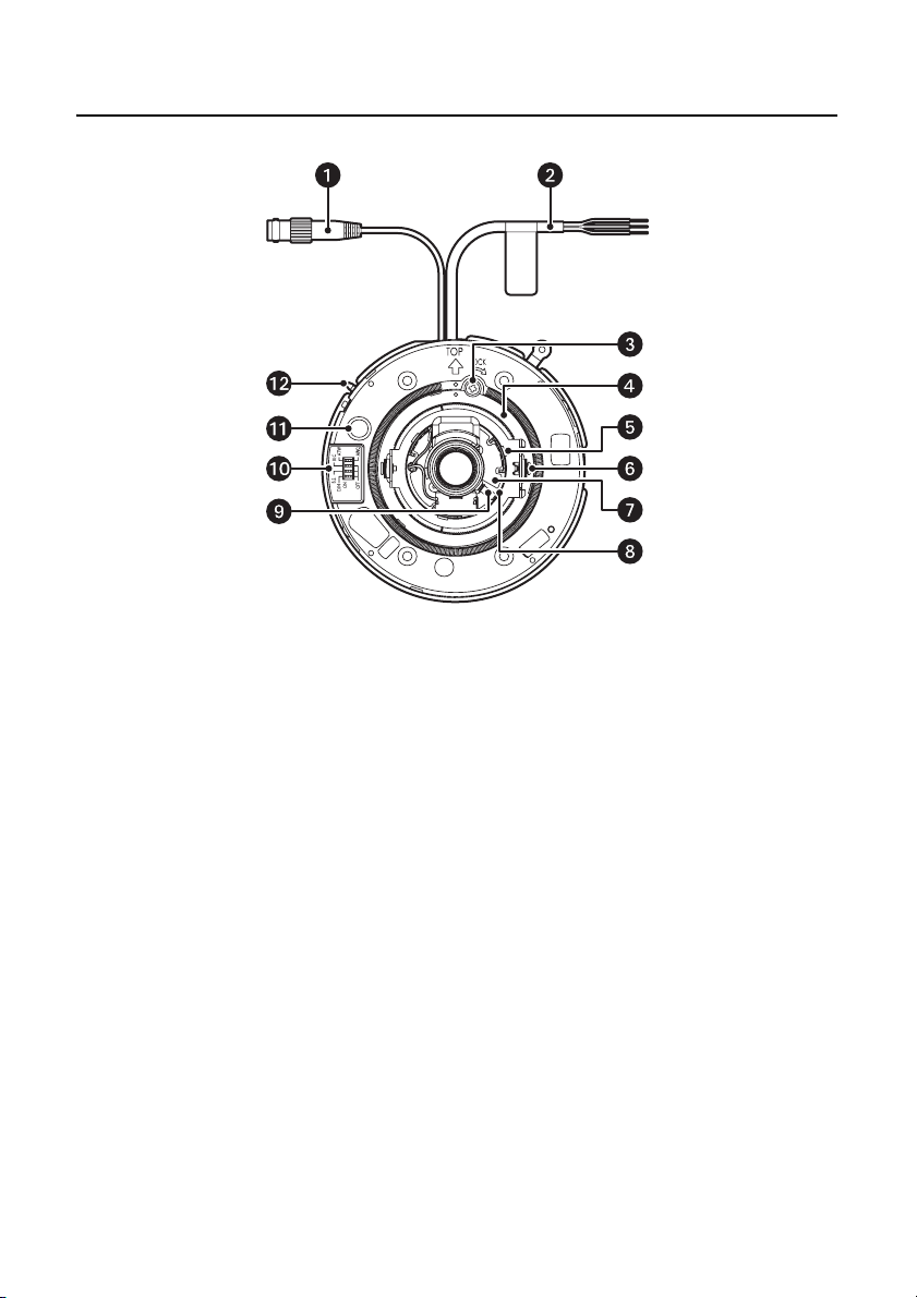
Product Overview
(Day/night model shown)
Figure 1. Product Overview of IS20-DN Camera
ì
Video Output Connector: Transmits composite video signals.
î
Power Cable: Supplies 24 V AC or 12 V DC from an external power source.
ï
Panning Table Lock Screw (LOCK): Fixes the panning table.
ñ
Panning Table: Adjusts the panning position of the camera.
ó
Tilting Table: Adjusts the tilting position of the camera.
r
Tilting Lock Screws (left and right): Fixes the tilting position.
s
Azimuth Adjuster: Adjusts the azimuth angle of the camera.
t
Zoom Lock Lever: Fixes the zoom position after adjusting.
u
Focus Lock Lever: Fixes the focus position after adjusting.
C3472M-C (9/10) 9
Page 10

~í
Dip Switch: Selects ON/OFF of white balance, backlight compensation, Adaptive Black Stretch or day/night
mode.
BLCB.S.
ATWD/N
ON
AWCOFF
Figure 2. Default Dip Switch Settings
Simple day/night mode selector (D/N) for color models:
ON: The camera selects black-and-white mode if the picture is dark, or color mode if the picture is bright
enough.
OFF (default): Color picture is displayed normally.
NOTE: The simple day/night function is established by using the SENSE UP function for black-white images.
The IR filter is secured.
Day/night mode selector [D/N] for day/night models:
ON: The camera selects black-and-white mode if the picture is dark, or color mode if the picture is bright
enough. When set to ON, The camera switches from color to black/white images when the ambient brightness
(illuminance) of the camera is approximately 0.6 lx or less.
OFF (default): Color picture is displayed normally.
NOTES:
• To obtain color images, a sufficient level of illuminance (approximately 30 lx or more) is required.
• The switching illuminance level varies depending on subjects and light sources.
• The switching illuminances described above are reference values. The switching illuminance shall be
decided based on the actual installation environment.
Adaptive black stretch selector (B.S.):
ON (default): The dark area of the object is automatically corrected to lighten it.
OFF: Does not compensate.
NOTE: In the case of “ON” setting, noise may be increased in the dark area of the object.
In addition, darkness and brightness may be emphasized in the vicinity of the boundary between the dark and
bright areas.
Backlight compensation selector (BLC):
ON: Compensates the background automatically if it is brighter than the object.
OFF (default): This mode is used when the front of the object is extremely bright.
NOTE: Under some conditions, such as extremely strong backlight, the desired compensation effect may not
be achieved even if the mode is set to ON to detect the backlight level.
White balance selector (ATW/AWC):
ATW (default): Activates the automatic color temperature tracking mode. The camera continuously measures
the color temperature of the light source and automatically adjusts the white balance. The adjustment of the
color temperature ranges from approximately. 2700 K to 6000 K.
AWC: Activates the automatic white balance control mode. This adjustment is suitable for a location where a
light source is stable. The adjustment of the color temperature ranges from approximately 2000 K to 10000 K.
~â
Monitor Output Jack (RCA jack): Connects the LCD monitor and such devices for checking images.
~ä
Marker: This marker is used when the top cover is installed.
10 C3472M-C (9/10)
Page 11

Installation
The following installation should be performed by qualified service personnel or system installers.
NOTES:
• Procure 4 mounting screws according to the material of the installation area. In this case, wood screws and
nails should not be used.
• The recommended tightening torque is M4: 1.6 N·m (16 kgf·cm).
• The required pullout capacity of a single screw/bolt is 196 N (20 kgf) or more.
• If a ceiling board, such as plaster board, is too weak to support the total weight, the area shall be sufficiently
reinforced.
• The protection sheet attached to the dome cover should be peeled off after installation.
DISASSEMBLING THE CAMERA
1. Peel off the protection sheet from the top cover (refer to Figure 3).
Do not remove completely as this protects the dome during installation.
Figure 3. Removing the Protection Sheet
2. Remove the top cover.
a. Unscrew the top cover fixing screw (refer to Figure 4).
Figure 4. Removing the Top Cover Fixing Screw
C3472M-C (9/10) 11
Page 12

b. Adjust the marker on this unit to “I” on the top cover, and turn the top cover counterclockwise to
remove it (refer to Figure 5).
NOTE: The dome cover and the inner dome cover are joined into a single unit; therefore, never try to
remove them.
Figure 5. Adjusting the Top Cover Marker
12 C3472M-C (9/10)
Page 13

MOUNTING THE CAMERA
The mounting requirements are shown as follows:
Mounting
Site Model
Ceiling/wall
Two-gang junction
box
Ceiling/wall
Surface mount M4 (or appropriate),
Recommended Screw and
Tightening Torque
M4 (or appropriate),
1.6 N·m (16 kgf·cm)
Number of
Screws
Minimum Pullout
Strength
4 pcs. 196 N/pc.(20 kgf/pc.)
4 pcs. 196 N/pc.(20 kgf/pc.)
1.6 N·m (16 kgf·cm)
Ceiling
*Make sure that the installed mount bracket can support more than five times the weight of the camera.
Flush mount – – *
USING A 2-GANG JUNCTION BOX
1. Install the 2-gang junction box (not supplied) onto the wall/ceiling.
a. When using a 2-gang junction box (4 x 4 inches), procure one locally that meets the dimensions in
Figure 6.
b. Locally procure four camera mounting screws suitable for the installation surface and structure of the
wall/ceiling or 2-gang junction box.
2. Mount the camera onto the 2-gang junction box with four screws (not supplied).
3. Fasten all of the mounting screws (refer to Figure 6).
Figure 6. Mounting the Camera to a 2-Gang Junction Box
ì
46 mm (1.81 inches)
î
83.5 mm (3.27 inches)
C3472M-C (9/10) 13
Page 14

SURFACE MOUNTING
1. Prepare the mounting space.
• If the camera is directly mounted on a wall/ceiling, align the camera mounting position with the
position of the hole through which the cables are routed, and then make the hole.
• If no hole is made through a wall/ceiling and open wiring along a wall/ceiling is used, remove the dust
guard cap, take out the cable, replace the dust guard cap, and then process the cover so that the
cables can be routed through the side of the cover.
2. Place the camera onto the wall/ceiling and mark four screw positions with a pen.
3. Mount the camera onto the wall/ceiling with the four screws (not supplied).
4. Fasten all of the mounting screws.
FLUSH MOUNTING
WARNING: Be careful when preparing the mounting hole. If the mounting hole is too large, the
ceiling mount bracket cannot be mounted securely.
1. Using the supplied template, prepare a mounting hole that is 160 mm (6.29 inches) in diameter.
2. Position two of the spring hooks of the camera (refer to Figure 7).
When the ceiling mount bracket is installed after positioning the spring hooks in the opposite side, they may
become difficult to pull out.
Figure 7. Positioning the Spring Hooks
ì
Main Body
î
Spring Hook
14 C3472M-C (9/10)
Page 15

3. Attach the ceiling mount bracket onto the ceiling board (refer Figure 8).
NOTE: Maximum thickness of the ceiling board is 30 mm (1.18 inches) for installation.
Loosen the clamping screws until the length between the clamp plates becomes wider than the thickness of
the ceiling board, and then clamp the ceiling board by tightening the clamping screws. The recommended
tightening torque is 0.61 N·m (6.0 kgf·cm).
Figure 8. Attaching the Ceiling Mount Bracket
ì
Main Body
î
Triangle Mark
ï
Clamp Plates
ñ
Clamping Screws
4. Connect the video cable and the power cord to the camera (refer to Wiring on page 16).
5. Attach the camera to the ceiling mount bracket using 4 fixing screws (supplied).
C3472M-C (9/10) 15
Page 16

WIRING
Figure 9. Video Output Connector and Power Cable
ì
Video Output Connector
î
Power Cable
VIDEO OUTPUT CONNECTION
NOTE: When connecting the coaxial cable to the video output connector, make sure that the connector of the
coaxial cable is locked firmly.
Connect the video output connector to the monitor, or other system devices, with coaxial cable (not supplied).
Table A. Maximum Extensible Cable Length
Cable Type
RG-59/U (3C-2V) 250 m
RG-6/U (5C-2V) 500 m
RG-11/U (7C-2V) 600 m
RG-15/U (10C-2V) 800 m
16 C3472M-C (9/10)
Extensible Length
(approximate)
Page 17

POWER CONNECTION
Connect the 3-conductor cable of the camera to the power supply.
Table B. Power Wire Colors and Functions
Wire Color 12 V DC 24 V AC
Brown Positive Live
Blue Negative Neutral
Green/yellow — Grounding
Figure 10. Power Cable
WARNINGS:
• Be sure to connect the GND (grounding) lead of the camera and grounding terminal of the
power supply when using a 24 V AC power source.
• Only connect this product to a 24 V AC or 12 V DC Class 2 power supply.
C3472M-C (9/10) 17
Page 18

CABLE LENGTH AND WIRE GAUGE
24 V AC
The voltage supplied to the power terminals of the camera should be within 19.5 V AC and 28 V AC.
Table C. 24 V AC Recommended Cable Length and Thickness
Copper Wire Size (AWG)
Length of Cable (approx.)
(m)
#24
(0.22 mm
20 30 45 75
2
)
#22
(0.33 mm2)
#20
(0.52 mm2)
#18
(0.83 mm2)
12 V DC
Use the formula below to calculate the power cable and power supply. The voltage supplied to the power terminals
of the camera should be within 10.8 V DC and 16 V DC.
Table D. 12 V DC Resistance of Copper Wire (at 20 °C)
Copper Wire Size (AWG)
#24 (0.22 mm
Resistance Ω/m
10.8 V DC ≤ V
A - 2 (R x I x L) ≤ 16 V DC
L = Cable length (m)
R = Resistance of copper wire (Ω/m)
A = DC output voltage of power supply unit
V
I = DC current consumption (A). Refer to Specifications on page 25.
2
) #22 (0.33 mm2) #20 (0.52 mm2) #18 (0.83 mm2)
0.078 0.050 0.03 0.018
18 C3472M-C (9/10)
Page 19

IMAGE ADJUSTMENT
PAN, TILT, AND AZIMUTH ADJUSTMENT
WARNINGS:
• Do not touch the iris motor.
• Do not hold the camera by the lens unit when adjusting pan, tilt, or azimuth.
1. Rotate the panning table (320-degree range) to adjust the panning position of the camera (refer to Figure 11).
The adjusting range is from +180 degrees (clockwise) to –140 degrees (counterclockwise).
2. Tighten the panning table lock screw.
140°
180°
Figure 11. Adjusting the Panning Position
ì
Indication
î
Panning Table Lock Screw
ï
Indication
ñ
Panning Table
C3472M-C (9/10) 19
Page 20

3. Rotate the tilting table (±75-degree range) to adjust the tilting position of the camera (refer to Figure 12).
NOTES:
• This lens can also be rotated in the reverse direction, but the image azimuth is reversed. In such a
case, turn the panning table to the 180-degree side to correct the azimuth image.
• When used at an angle that is close to horizontal, the shadow of the dome cover may be projected.
75°75°
Figure 12. Adjusting the Tilting Position (Day/Night Model Shown)
ì
Tilting Lock Screw
4. Tighten both the panning table lock screw and the tilting lock screws on both sides after adjusting the tilt
position of the camera. The recommended tightening torque is 0.59 N.m (6 k
5. Rotate the azimuth adjuster (±100-degree range) to adjust the azimuth angle of the image (refer to Figure 13).
g
f.cm).
100°100°
Figure 13. Adjusting the Azimuth Angle (Color Model Shown)
ì
Indication
î
Azimuth Adjuster
20 C3472M-C (9/10)
Page 21

ZOOM AND FOCUS ADJUSTMENT
1. Loosen the zoom lock lever and move the lever between TELE and WIDE to obtain the appropriate angle of
view (refer to Figure 14).
2. Tighten the zoom lock lever.
3. Loosen the focus lock lever and move the lever between FAR and NEAR to obtain the optimum focus.
4. Tighten the focus lock lever.
NOTE: You can change the angle of view by moving the zoom lock lever, and you can move the focus lock lever to
adjust the focus.
Figure 14. Adjusting the Zoom and Focus
ì
Focus Lock Lever
î
Zoom Lock Lever
C3472M-C (9/10) 21
Page 22

ASSEMBLING THE CAMERA
1. Mount the top cover (refer to Figure 15):
a. Adjust the marker of this unit to “I” on the top cover to install the top cover.
Figure 15. Mounting the Top Cover
ì
Marker
î
Top Cover
ï
Dome Cover Block
b. Rotate the top cover clockwise to adjust the marker to “II.”
22 C3472M-C (9/10)
Page 23

c. Turn the dome cover block to the right and left while watching the monitor. Make adjustments so that
no eclipse is caused.
WARNING: If the dome cover block is moved with unreasonable force, it may break.
d. Rotate the top cover clockwise to adjust the marker to “III.”
2. Secure the top cover and the camera main unit with an accessory fixing screw (M3).
Figure 16. Securing the Top Cover
C3472M-C (9/10) 23
Page 24

3. (Flush mount models only) Attach the supplied flush mount cover:
a. Match the logos on the cover and on the main body of the camera.
b. Pull out both of the spring hooks and attach the hooks to the cover.
c. Make sure that the cover is attached to the ceiling with no space between them.
Figure 17. Attaching the Flush Mount Cover
ì
Spring Hooks
î
Cover
24 C3472M-C (9/10)
Page 25

Specifications
Power Source and Consumption
PAL 24 V, 50 Hz, 2.7 W (AC); 12 V, 220 mA (DC)
NTSC 24 V, 60 Hz, 2.7 W (AC); 12 V, 220 mA (DC)
Image Sensor 1/3 inch interline transfer CCD
Effective Pixels
PAL 752 (H) x 582 (V)
NTSC 768 (H) x 494 (V)
Scanning Area 4.9 (H) x 3.7 (V) mm (0.19" x 0.15")
Scanning System 2:1 interlace
Scanning Lines
PAL 625 lines
NTSC 525 lines
Scanning Frequency PAL NTSC
Horizontal 15.625 kHz 15.734 kHz
Vertical 50.00 Hz 59.94 Hz
Synchronization Internal
Resolution
Horizontal 540 TV lines (at center)
Vertical 400 TV lines (PAL, at center); 350 TV lines (NTSC at center)
Video Output 1.0 V[p-p] PAL/NTSC composite 75 Ω
White Balance ATW/AWC
Signal-to-Noise Ratio 50 dB (equivalent to AGC Off, weight On)
Minimum Illumination at F1.3 (WIDE)
Clear Dome 0.6 lx (C/L), 0.05 lx (B/W, day/night models), 0.4 lx (B/W, color models)
Smoked Dome 1.7 lx (C/L), 0.15 lx (B/W, day/night models), 1.1 lx (B/W, color models)
Switch Function White balance selector (ATW/AWC), backlight compensation selector
Lens 3.6X variable focal lens
Focal Length 2.8 to 10.0 mm (0.11 to 0.39")
F Number F1.3 (WIDE) to F3.1 (TELE)
Focus Range ∞ to 1.2 m (3.9 ft)
Angle of View HorizontalVertical
Day/Night Models 100°50’ (WIDE) to 27°39’ (TELE) 73°51’ (WIDE) to 20°45’ (TELE)
Color Models 100°18’ (WIDE) to 27°39’ (TELE) 73°33’ (WIDE) to 20°45’ (TELE)
Adjusting Angle
Panning range +180° to –140°
Tilting range ±75°
Azimuth range ±100°
Ambient Temperature –10 °C to +50 °C
Ambient Humidity Less than 90%
Dimensions
Surface Mount ø129.5 mm x 93 mm (H) (ø5.1 x 3.66")
Flush Mount ø186 mm x 110 mm (H) (ø7.32 x 4.33")
Weight
Surface Mount 430 g (0.95 lb)
Flush Mount 710 g (1.57 lb)
(ON/OFF), adaptive black stretch selector (ON/OFF), day/night mode
selector (ON/OFF)
C3472M-C (9/10) 25
Page 26

(Weights and dimensions indicated are approximate.)
5.10 (12.95)
3.66 (9.30)
1.89 (4.80)
3.29 (8.35)
Ø 5.10 (12.95)
0.18 (0.45)
1.81 (4.60)
Ø 0.16-0.18
(0.40-0.45)
Ø 1.58 (4.00)
7.32 (18.60)
Ø 1.58 (4.00)
HOLE IN THE CEILING Ø 6.30 (16.00)
Ø 1.18-1.97
(3.00-5.00)
2.36 (6.00)1.97 (5.00)
MAX 1.18 (3.00)0.30 (0.75)
NOTE: VALUES IN PARENTHESES ARE CENTIMETERS; ALL OTHERS ARE INCHES.
Information on disposal for users of waste electrical and electronic equipment (private households)
This symbol on the products and/or accompanying documents means that used electrical and electronic products should not
be mixed with general household waste.
For proper treatment, recovery and recycling, please take these products to designated collection points, where they will be
accepted on a free of charge basis. Alternatively, in some countries you may be able to return your products to your local
retailer upon the purchase of an equivalent new product.
Disposing of this product correctly will help to save valuable resources and prevent any potential negative effects on human
health and the environment which could otherwise arise from inappropriate waste handling. Please contact your local
authority for further details of your nearest designated collection point.
Penalties may be applicable for incorrect disposal of this waste, in accordance with national legislation.
For business users in the European Union
If you wish to discard electrical and electronic equipment, please contact your dealer or supplier for further information.
Information on disposal in other countries outside the European Union
This symbol is only valid in the European Union.
If you wish to discard this product, please contact your local authorities or dealer and ask for the correct method of disposal.
26 C3472M-C (9/10)
Page 27

PRODUCT WARRANTY AND RETURN INFORMATION
WARRANTY
Pelco will repair or replace, without charge, any merchan dise proved defective in material or workmanship for a period of one year after the date of shipment.
Exceptions to this warranty are as noted below:
• Five years:
– Fiber optic products
– Unshielded Twisted Pair (UTP) transmission products
– CC3701H-2, CC3701H-2X, CC3751H-2, CC3651H-2X, M C3651H-2, and MC3651H-2X camera models
• Three years:
– Pelco-designed fixed network cameras and n etwork dome cameras with Sarix™ technology.
– Pelco-branded fixed camera models (CCC1390H Series, C10DN Se ries, C10CH Series, and IP3701H Series)
– EH1500 Series enclosures
®
– Spectra
IV products (including Spectra IV IP)
– Camclosure
– DX Series digital video recorders (except DX9000 Series which is cove red for a period of one year), DVR5100 Series digital video recorders, Digital Sent ry
– Endura
– Genex® Series products (multiplexers, server, and keyboard)
– PMCL200/300/400 Series LCD monitors
– PMCL5xx Series FHD monitors
• Two years:
– Standard varifocal, fixed foca l, and motorized zoom lenses.
– DF5/DF8 Series fixed dome products
– Legacy® Series integrated positioning systems
– Spectra III™, Spectra Mini, Spectra Mini IP, Esprit®, ExSite®, and PS20 scanners, including when u sed in continuous motion applications.
– Esprit Ti and TI2500 Series thermal imaging products
– Esprit and WW5700 Series window wip er (excluding wiper blades).
– CM6700/CM6800/CM9700 Series matrix
– Digital Light Processing (DLP®) displays (except lamp and color wheel). The lamp and color wheel will be covered for a period of 90 days. The air filter is
– Intelli-M
•One year:
– Video cassette recorders (VCRs), except video heads. Video heads will be covered for a period of six month s.
• Six months:
– All pan and tilts, scanners, or preset lenses u sed in continuous motion applications (preset scan, tour, and auto scan modes).
Pelco will warrant all replacement par ts and repairs for 90 days from the date of Pelco shipment. All goods requir ing warranty repair shall be sent freight prepaid
to a Pelco designated location. Repairs m ade necessary by reason of misuse, alteration, normal wear, or accident are not covered under this warranty.
Pelco assumes no risk and shall be subject to no liability for damages or loss resulting from the specific use or applica tion made of the Products. Pelco’s liability for any
claim, whether based on breach of contract, negligence, infringement of any rights of any party or product liability, relating to the Products shall not exceed the price
paid by the Dealer to Pelco for such Products. In no event will Pelco be liable for any special, incidental, or consequential damages (including loss o f use, loss of profit,
and claims of third parties) however caused, whet her by the negligence of Pelco or otherwise.
The above warranty provides the Dealer w ith specific legal rights. The Dealer may also have additional rights, which are subject to variation from state to state.
If a warranty repair is required, the Dealer must contact Pelco at (800) 289-9100 or (559) 292-1981 to obtain a Repair Authorization number (RA), and provide the
following information:
1. Model and serial number
2. Date of shipment, P.O. number, sales order number, or Pelco invoice number
3. Details of the defect or problem
If there is a dispute regarding the warranty of a product that does not fall under the warranty conditions stated above, please include a written explana tion with
the product when returned.
Method of return shipment shall be the same or equal to the method by which the item was received by Pelco.
RETURNS
To expedite parts returned for repair or credit, please call Pelco at (800) 289-9100 or (559) 292-1981 to obtain an authorization number (CA number if returned for
credit, and RA number if returned for r epair) and designated return location.
All merchandise returned for credit may be subject to a 20 percent restocking and refurbishing charge.
Goods returned for repair or credit should be clearly identified with the assigned CA or RA number and freight should be prepaid.
REVISION HISTORY
Manual # Date Comments
C3472M 6/10 Original version.
C3472M-A 7/10 Made minor formatting and specification changes, including a new dimension drawing.
C3472M-B 8/10 Made changes to Important Safety Instructions and Regulatory Notices to comply with manufacturing
C3472M-C 9/10 Added color and day/night model information to cover page and product description.
Pelco, the Pelco logo, and other trademarks associat ed with Pelco products referred to in this publication are trademarks of Pelco, I nc. or its affiliates.
All other product names and services are t he property of their respective companies.
Product specifications and availability are subject to change without notice.
©Copyright 2010, Pelco, Inc. All rights reserved.
®
Series (IS, ICS, IP) integrated camera systems
Series hardware products, DVX Series digital vid eo recorders, and NVR300 Series network video recorders
®
Series distributed network-based video products
not covered under warranty.
®
eIDC controllers
requests.
2-10-10
®
Page 28

www.pelco.com
Pelco, Inc. Worldwide Headquarters 3500 Pelco Way Clovis, California 93612 USA
USA & Canada Tel (800) 289-9100 Fax (800) 289-9150
International Tel +1 (559) 292-1981 Fax +1 (559) 348-1120
 Loading...