

Page 1

Addendum
IS90/IS110/IS150
Series Camclosure
®
C3438M (5/07)
Page 2

Introduction
This addendum updates the camera adjustment sections in the IS90, IS110, and IS150 Series
Camclosure
• IS90 (C3425M)
• IS110 (C3426M)
• IS150 (C3427M)
For all DN/CH/C models, refer to DN/CH/C Series Adjustments on page 3.
For all DW/CW models, refer to DW/CW Series (Wide Dynamic Range) Adjustments on page 7.
®
Installation manuals.
– DN/CH/C Series Adjustments (pages 18-20)
– DW/CW Series Adjustments (pages 21-23)
– DN/CH Series Adjustments (pages 18-20)
– DW/CW Series Adjustments (pages 21-23)
– DN/CH/C Series Adjustments (pages 15-17)
– DW/CW Series Adjustments (pages 18-20)
2 C3438M (5/07)
Page 3
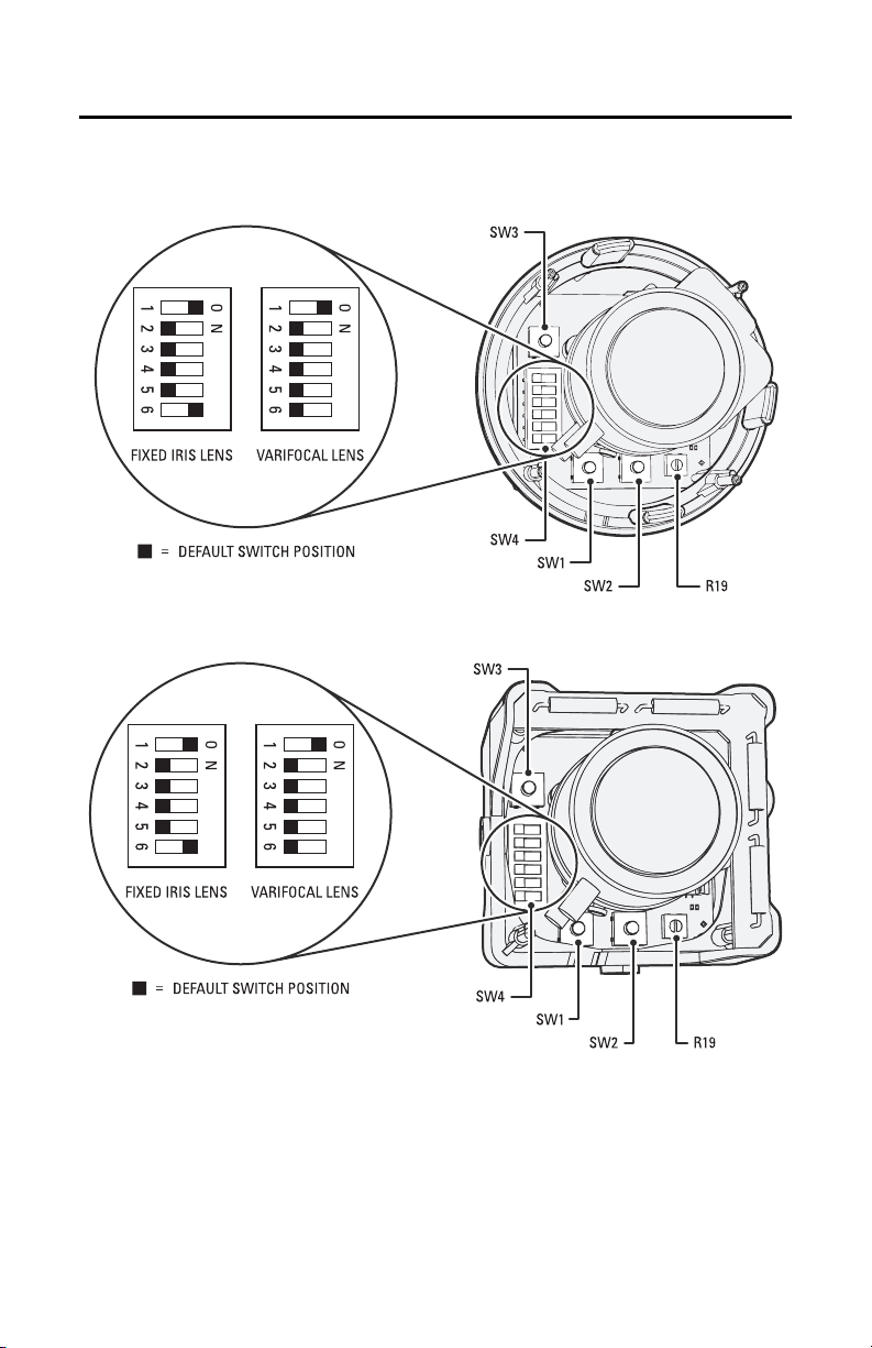
DN/CH/C Series Adjustments
Refer to Figure 1 to adjust IS90-DN/CH/C models. Refer to Figure 2 to adjust IS110-DN/CH or
IS150-DN/CH models.
Figure 1. Adjusting an IS90-DN/CH/C Series Camclosure
Figure 2. Adjusting an IS110-DN/CH or IS150-DN-CH Series Camclosure
C3438M (5/07) 3
Page 4

SWITCH SETTINGS
Locate the DIP switch. Then set the switches for your installation.
SW4-1: AGC (Auto Gain Control)
The AGC (automatic gain control) adjusts the image automatically to compensate for changes in light
levels.
Set to ON to enable AGC. Set to OFF to disable AGC. The default is ON.
SW4-2: BLC (Backlight Compensation)
The BLC (backlight compensation) feature compensates for backlit scenes by enhancing objects in the
center of the scene.
Set to ON to enable BLC. Use this setting if a bright backlight is present and the subject in the center
of the picture appears dark or as a silhouette.
Set to OFF to disable backlight compensation. This is the default.
SW4-3: Line Sync
When multiple cameras are connected to the same switching device, vertical roll may occur on the
monitor. AC line lock eliminates vertical roll by locking the frame rate to the power supply frequency.
Each camera output is synchronized to the power supply frequency. (Refer to Vertical Phase
Adjustment on page 5 for more information.)
Internal line sync disables line lock and synchronizes cameras internally.
Set to OFF to use AC line lock. Set to ON to use internal line sync. The default is OFF.
SW4-4: Flickerless
In certain lighting conditions, a flicker in the light source may affect camera operation. Flickering can
be caused by a number of conditions, including the quality of the source power and the age and type
of fluorescent bulbs and ballasts.
Set to ON to enable flickerless operation. The camera will remove the effects of flickering when
present. The shutter speed will be set to 1/120 (NTSC) or 1/100 (PAL).
Set to OFF to disable flickerless operation. This is the default.
NOTE: If you enable flickerless operation, you should use AC line lock for best results.
SW4-5: AWB (Auto White Balance)/MWB (Manual White Balance)
Auto white balance is enabled by default (OFF).
To manually set and lock the white balance:
1. Set SW4-5 to OFF.
2. Hold a white background in front of the lens until the video shows all white.
3. While holding the background in place, set SW4-5 to ON. A blue blinking block appears on the video image for a few seconds. When the block changes to solid green, the manual white balance process is complete.
SW4-6: Reserved
Do not change SW4-6 from its factory setting. SW4-6 must be set to OFF for Varifocal models; it must
be set to ON for fixed-iris lenses.
4 C3438M (5/07)
Page 5

AUTO IRIS LEVEL ADJUSTMENT
To adjust the auto iris DC-drive level (refer to Figure 1 or Figure 2 on page 3):
1. Tilt or rotate the camera module until you can access the auto iris level control (R19).
2. Turn the screw clockwise to increase the brightness level or counterclockwise to decrease the brightness level.
VERTICAL PHASE ADJUSTMENT
NOTE: Use this procedure for 24 VAC operation only.
When using more than one camera power supply, a brief vertical roll may occur on the monitor when
switching from one camera to another.
To eliminate vertical roll, reverse the 24 VAC connections on one camera. If both cameras are
connected to the same transformer, this should solve the problem. If the problem still exists, adjust
the phase control by synchronizing, or line-locking, the cameras to one another.
NOTE: When adjusting vertical phase, line sync (SW4-3) must be set to OFF for AC line lock.
Adjusting Vertical Phase
You may need two people when synchronizing the cameras: one at the camera, the other at the
monitor to observe the vertical roll and the effect of any camera adjustments.
To synchronize the cameras:
1. Choose a reference camera to which all other cameras will be phased.
2. Select the camera to synchronize. Use buttons SW1 and SW2 to synchronize the camera to the reference camera (refer to Figure 1 or Figure 2 on page 3). SW1 increases vertical phase; SW2 decreases vertical phase.
3. Each time an adjustment is made, switch back and forth between the camera you are adjusting and the reference camera. Repeat this process as many times as necessary until the roll between the cameras is no longer noticeable.
4. Adjust the phase of all other cameras by repeating steps 2 through 3. Always adjust to the reference camera selected in step 1.
NOTE: The preferred method for camera phase adjustment is to use a dual trace oscilloscope to align
the vertical sync pulses of the reference camera to the selected camera(s).
BLEMISH DETECTION
If small white or color spots appear in the video image, one or more pixels on the camera imager may
be defective. (This condition is common for both CCD and CMOS imagers.)
DN, CH, and C Series cameras with auto iris lenses automatically detect and correct defective pixels
during startup. Video turns on, then off, and then on again. If white or color spots still appear, you can
correct the defective pixels manually.
CH and C Series cameras with fixed iris lenses do not automatically detect and correct defective
pixels. You can correct the defective pixels manually.
C3438M (5/07) 5
Page 6

To manually correct defective pixels (refer to Figure 1 or Figure 2 on page 3):
1. Cover the lens completely. Make sure no light can enter the lens.
NOTE: The mechanical iris lens aperture does not completely block the light.
2. Press and hold button SW3 for one second. The camera will find and correct defective pixels.
NOTE: Any defective pixels that cannot be completely corrected may still appear.
3. Release button SW3.
4. Uncover the lens for normal camera operation.
DAY/NIGHT OPERATION
NOTE: This section only applies to DN modelcameras.
DN model cameras regularly check the brightness level of the field of view to determine when to
switch between day (color) and night (black-white) operation.
Actual brightness threshold levels are affected by camera angle, amount of zoom, field of view, lens,
and type of lighting. The switching process lasts from seven to 10 seconds.
Figure 3 and Table A show how the camera switches between color and black-white operation.
MODE
COLOR
MODE
3.0 lux
COLOR
B-W
1.5 lux
MODE
FALLING LIGHT LEVEL
B-W
RISING LIGHT LEVEL
MODE
Figure 3. Threshold Switching Levels
Tab le A. Approximate Switching Thresholds
Color to B-W 1.5 lux ±1.0 lux
B-W to Color 3.0 lux ±1.0 lux
NOTE: These switching thresholds are approximate. Actual thresholds are affected by lens type and
setting, field of view, scene, and other factors. Use the thresholds in Table A as a guide when
installing the unit.
6 C3438M (5/07)
Page 7

DW/CW Series (Wide Dynamic Range) Adjustments
Refer to Figure 4 to adjust IS90-DW/CW models. Refer to Figure 5 to adjust IS110-DW/CW or
IS150-DW/CW models.
R7
Figure 4. Adjusting an IS90-DW/CW Series Camclosure
R7
Figure 5. Adjusting an IS110-DW/CW or IS150-DW/CW Series Camclosure
C3438M (5/07) 7
Page 8

SWITCH SETTINGS
Locate the DIP switch. Then set the switches for your installation.
SW1-1: Video Format
Set to ON for NTSC. Set to OFF for PAL. The default is ON.
SW1-2: Line Sync
When multiple cameras are connected to the same switching device, vertical roll may occur on the
monitor. AC line lock eliminates vertical roll by locking the frame rate to the power supply frequency.
Each camera output is synchronized to the power supply frequency. (Refer to Vertical Phase
Adjustment on page 10 for more information.)
Internal line sync disables line lock and synchronizes cameras internally.
Set to ON to use AC line lock. Set to OFF to use internal line sync. The default is ON.
SW1-3: Interlaced Scanning/Progressive Scanning
Interlaced scanning is the standard for analog recording installations. Each frame contains one odd
and one even field, each processed separately.
Progressive scanning is better for digital recording installations. Each frame is processed as a whole,
which results in less blurring and cleaner digital conversion. It also saves storage space on digital
video recorders.
Set to ON to select interlaced scanning. Set to OFF to select progressive scanning. The default is ON.
SW1-4: AWB (Auto White Balance)/MWB (Manual White Balance)
Auto white balance is enabled by default (ON).
To manually set and lock the white balance:
1. Set SW1-4 to ON.
2. Hold a white background in front of the lens until the video shows all white.
3. While holding the background in place, set SW1-4 to OFF. A green block and a white block alternate briefly on the video image until the manual white balance process is complete.
SW1-5: Fluorescent/General
Enable this option to adjust the camera for best operation under fluorescent lighting.
Set to OFF for fluorescent lighting. Set to ON for general lighting. The default is ON.
NOTE: If you use fluorescent operation, you should use AC line lock for best results.
SW1-6: General WDR/Maximum WDR
Maximum WDR supports about 36 dB of additional dynamic range over a standard camera. Use it for
installations that require the maximum WDR.
General WDR supports about 20 dB of additional dynamic range over a standard camera. Use it for
installations that do not require the maximum WDR.
Set to ON to select maximum WDR. Set to OFF to select general WDR. The default is ON.
8 C3438M (5/07)
Page 9

SW1-7: DSS (Digital Slow Shutter)
The default shutter speed for NTSC is 30 frames per second (fps). It is 25 fps for PAL. This is also
known as SENS 2X.
You can decrease the shutter speed to 7.5 fps (NTSC) or 6.25 fps (PAL). This is known as SENS 8X,
which improves low light sensitivity.
Set to ON to select SENS 2X. Set to OFF to select SENS 8X. The default is ON.
SW1-8: Day/Night Operation (DW models only)
NOTE: On CW models, SW1-8 is unused and does not affect camera operation.
DW model cameras regularly check the brightness level of the field of view to determine when to
switch between day (color) and night (black-white) operation. Use SW1-8 to set the general light
levels at which the camera will automatically switch.
Set to ON (dark) to use standard thresholds to switch between color and black-white operation. This
is the default.
Set to OFF (dusk) to use higher light thresholds to switch between color and black-white operation.
Actual brightness threshold levels are affected by camera angle, amount of zoom, field of view, lens,
and type of lighting. The switching process lasts from seven to 10 seconds.
Figure 6 and Table B show how the camera switches between color and black-white operation for
each setting.
MODE
COLOR
B-W
MODE
RISING LIGHT LEVEL
MODE
COLOR
3.0 lux
FALLING LIGHT LEVEL
1.0 lux
B-W
MODE
MODE
COLOR
B-W
MODE
RISING LIGHT LEVEL
FALLING LIGHT LEVEL
MODE
COLOR
B-W
MODE
7.0 lux
4.0 lux
DARK
DUSK
Figure 6. Threshold Switching Levels
Tab le B. Approximate Switching Thresholds
Dark (ON) Dusk (OFF)
Color to B-W 1.0 lux 4.0 lux
B-W to Color 3.0 lux 7.0 lux
NOTE: These switching thresholds are approximate and were measured using a 3.0 mm to 9.5 mm
lens at F1.0. Actual thresholds are affected by lens type and setting, field of view, scene, and other
factors. Use the thresholds in Table B as a guide when installing the unit.
C3438M (5/07) 9
Page 10

AUTO IRIS LEVEL ADJUSTMENT
The electronics of the IS90-DW and IS90-CW Series Camclosures automatically adjust the camera to
the auto iris. Auto iris level adjustments are not necessary.
VERTICAL PHASE ADJUSTMENT
NOTE: Use this procedure for 24 VAC operation only.
When using more than one camera power supply, a brief vertical roll may occur on the monitor when
switching from one camera to another.
To eliminate vertical roll, reverse the 24 VAC connections on one camera. If both cameras are
connected to the same transformer, this should solve the problem. If the problem still exists, adjust
the phase control by synchronizing, or line-locking, the cameras to one another.
NOTE: When adjusting vertical phase, line sync (SW1-2) must be set to ON for AC line lock.
Adjusting Vertical Phase
You may need two people when synchronizing the cameras: one at the camera, the other at the
monitor to observe the vertical roll and the effect of any camera adjustments.
To synchronize the cameras:
1. Choose a reference camera to which all other cameras will be phased.
2. Select the camera to synchronize. Use the phase adjustment control (R7) to synchronize the
camera to the reference camera (refer to Figure 4 or Figure 5 on page 7). Turn R7 clockwise to
increase vertical phase; turn R7 counterclockwise to decrease vertical phase.
3. Each time an adjustment is made, switch back and forth between the camera you are adjusting and the reference camera. Repeat this process as many times as necessary until the roll between the cameras is no longer noticeable.
4. Adjust the phase of all other cameras by repeating steps 2 through 3. Always adjust to the reference camera selected in step 1.
NOTE: The preferred method for camera phase adjustment is to use a dual trace oscilloscope to align
the vertical sync pulses of the reference camera to the selected camera(s).
BLEMISH DETECTION
If small white or color spots appear in the video image, one or more pixels on the camera imager may
be defective. (This condition is common for both CCD and CMOS imagers.)
DW and CW Series cameras have auto iris lenses and automatically detect and correct defective
pixels during startup. Manual pixel correction is not available.
10 C3438M (5/07)
Page 11

PRODUCT WARRANTY AND RETURN INFORMATION
WARRANTY
Pelco will repair or replace, without charge, an y merchandise proved defective in material or workmanship for a period of one year after the date of
shipment.
Exceptions to this warranty are as noted below:
• Five years on fiber optic products and TW3000 Serie s unshielded twisted pair transmission products.
• Three years on Spectra® IV products.
• Three years on Genex® Series products (multiplexers, server, and keyboard).
• Three years on Camclosure® and fixed camera models, except the CC3701H-2, CC3701H-2X, CC3751H-2, CC3651H-2X, MC3651H-2, and
MC3651H-2X camera models, which have a five-year warranty.
• Three years on PMCL200/300/400 Series LCD monit ors.
• Two years on standard motorized or fixed focal length lenses.
• Two years on Legacy®, CM6700/CM6800/CM9700 Series matrix, and DF5/DF8 Series fixed dome products.
• Two years on Spectra III™, Esprit®, ExSite®, and PS20 scanners, including when used in continuous mot ion applications.
• Two years on Esprit and WW5700 Series window wiper (excluding wiper blades).
• Two years (except lamp and color wheel) on Digital Light Processing (DLP®) displays. The lamp and color wheel will be cover ed for a period of
90 days. The air filter is not covered un der warranty.
• Eighteen months on DX Series digital video recorders, NVR300 Series network video recorders, and Endura™ Series distributed network-based video
products.
• One year (except video heads) on video cassette recorders (VCRs). Video heads will be covered for a period of six months.
• Six months on all pan and tilts, scanners or prese t lenses used in continuous motion applications (that is, preset scan, tour and auto scan mode s).
Pelco will warrant all replacement p arts and repairs for 90 days from the date of P elco shipment. All goods requiring warranty rep air shall be sent freight
prepaid to Pelco, Clovis, California. Repairs made necessary by reason of misuse, alteration, normal wear, or accident are not covered under this
warranty.
Pelco assumes no risk and shall be subject to no liability for damages or loss resulting from the sp ecific use or application made of the Products. Pelco’s
liability for any claim, whether based on breach of contract, negligence, infringement of an y rights of any party or product liability, relating to the Products
shall not exceed the price paid by the Dealer to Pelco for such Products. In no event will Pelco be liable for any special, incidental or consequential
damages (including loss of use, loss of prof it and claims of third parties) however caused, whether by the negligence of Pelco or otherwise.
The above warranty provides the Dealer with spe cific legal rights. The Dealer may also have additional right s, which are subject to variation from state
to state.
If a warranty repair is required, the Dealer must contact Pelco at (800) 289-9100 or (559) 292-1981 to obtain a Repair Authorization number (RA), and
provide the following information:
1. Model and serial number
2. Date of shipment, P.O. number, Sales Order number, or Pelco invoice number
3. Details of the defect or problem
If there is a dispute regarding the warranty of a p roduct which does not fall under the warranty conditions stated above, please in clude a written
explanation with the product wh en returned.
Method of return shipment shall be the same or equal to the method by which the item was received by Pelco.
RETURNS
In order to expedite parts returned to the factory for repair or credit, plea se call the factory at (800) 289-9100 or (559) 292-1981 to obtain an autho rization
number (CA number if returned for credit, and RA number if returned for repair).
All merchandise returned for credit may be subject to a 20% restocking and refurbishing charge.
Goods returned for repair or credit sh ould be clearly identified with the assigned CA or RA number and fr eight should be prepaid. Ship to the appropriate
address below.
If you are located within the continental U.S., Alaska, Hawaii or Puerto Rico, send goods to:
Service Department
Pelco
3500 Pelco Way
Clovis, CA 93612-5699
If you are located outside the continental U.S., Alaska, Hawaii or Puerto Rico and are instructed to return goods to the USA, you may do one of the
following:
If the goods are to be sent by a COURIER SERVICE, send the go ods to:
Pelco
3500 Pelco Way
Clovis, CA 93612-5699 USA
If the goods are to be sent by a FREIGHT FORWARDER, send the good s to:
Pelco c/o Expeditors
473 Eccles Avenue
South San Francisco, CA 94080 USA
Phone: 650-737-1700
Fax: 650-737-0933
REVISION HISTORY
Manual # Date Comments
C3438M 5/07 Original version.
Pelco, the Pelco logo, Camclosure, Esprit, Genex, Legacy, and Spectra are registered trademarks of Pelco. ©Copyright 2007, Pelco.
Endura, ExSite, and Spectra III are trademarks of Pelco. All rights reserved.
DLP is a registered trademark of Texas Instruments, Inc.
Page 12

Worldwide Headquarters
3500 Pelco Way
Clovis, California 93612 USA
USA & Canada
Tel: 800/289-9100
Fax: 800/289-9150
International
Tel: 1-559/292-1981
Fax: 1-559/348-1120
www.pelco.com
ISO9001
Australia|Canada|Finland|France|Germany|Italy|Macau|The Netherlands|Russia|Singapore
South Africa
Spain|Sweden|United Arab Emirates|United Kingdom|United States
|
 Loading...