

Page 1
INSTALLATION
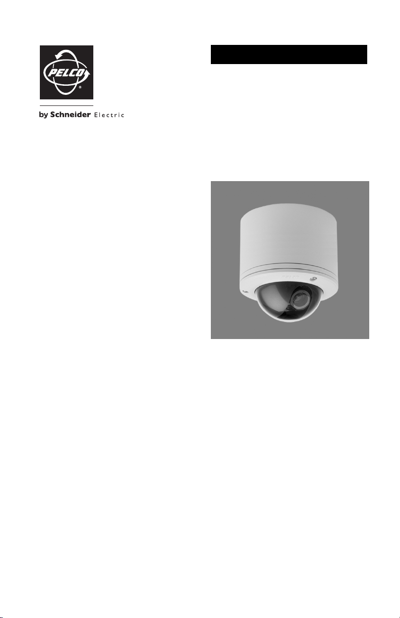
IP110 Series
Camclosure
Integrated Camera System
®
C3432M-G (4/09)
Page 2

Page 3

Contents
Important Safety Instructions. . . . . . . . . . . . . . . . . . . . . . . . . . . . . . . . . . . . . . . . . . . . . . . . . . . . . . . . . . . . . 6
Regulatory Notices. . . . . . . . . . . . . . . . . . . . . . . . . . . . . . . . . . . . . . . . . . . . . . . . . . . . . . . . . . . . . . . . . . . . . 7
Open Source Software Notice . . . . . . . . . . . . . . . . . . . . . . . . . . . . . . . . . . . . . . . . . . . . . . . . . . . . . . . . . . . . 8
Description . . . . . . . . . . . . . . . . . . . . . . . . . . . . . . . . . . . . . . . . . . . . . . . . . . . . . . . . . . . . . . . . . . . . . . . . . . . 9
Models . . . . . . . . . . . . . . . . . . . . . . . . . . . . . . . . . . . . . . . . . . . . . . . . . . . . . . . . . . . . . . . . . . . . . . . . . 9
Parts List. . . . . . . . . . . . . . . . . . . . . . . . . . . . . . . . . . . . . . . . . . . . . . . . . . . . . . . . . . . . . . . . . . . . . . . . 9
Basic System Configurations . . . . . . . . . . . . . . . . . . . . . . . . . . . . . . . . . . . . . . . . . . . . . . . . . . . . . . . . . . . . 10
Cover and Back Box Installation. . . . . . . . . . . . . . . . . . . . . . . . . . . . . . . . . . . . . . . . . . . . . . . . . . . . . . . . . . 12
Basic Surface Installation . . . . . . . . . . . . . . . . . . . . . . . . . . . . . . . . . . . . . . . . . . . . . . . . . . . . . . . . . 12
4S Electrical Box Installation . . . . . . . . . . . . . . . . . . . . . . . . . . . . . . . . . . . . . . . . . . . . . . . . . . . . . . . 13
404 Plaster Ring Installation . . . . . . . . . . . . . . . . . . . . . . . . . . . . . . . . . . . . . . . . . . . . . . . . . . . . . . . 14
Side Conduit Installation . . . . . . . . . . . . . . . . . . . . . . . . . . . . . . . . . . . . . . . . . . . . . . . . . . . . . . . . . . 15
Wiring Tables . . . . . . . . . . . . . . . . . . . . . . . . . . . . . . . . . . . . . . . . . . . . . . . . . . . . . . . . . . . . . . . . . . . . . . . . 16
Cat5 Cable . . . . . . . . . . . . . . . . . . . . . . . . . . . . . . . . . . . . . . . . . . . . . . . . . . . . . . . . . . . . . . . . . . . . . 16
Alarm and 24 VAC Wires . . . . . . . . . . . . . . . . . . . . . . . . . . . . . . . . . . . . . . . . . . . . . . . . . . . . . . . . . . 17
Connecting a Relay Device. . . . . . . . . . . . . . . . . . . . . . . . . . . . . . . . . . . . . . . . . . . . . . . . . . . . 17
Connecting Alarms . . . . . . . . . . . . . . . . . . . . . . . . . . . . . . . . . . . . . . . . . . . . . . . . . . . . . . . . . . 18
Camera Module . . . . . . . . . . . . . . . . . . . . . . . . . . . . . . . . . . . . . . . . . . . . . . . . . . . . . . . . . . . . . . . . . . . . . . 19
Camera Orientation . . . . . . . . . . . . . . . . . . . . . . . . . . . . . . . . . . . . . . . . . . . . . . . . . . . . . . . . . . . . . . 19
Module Installation . . . . . . . . . . . . . . . . . . . . . . . . . . . . . . . . . . . . . . . . . . . . . . . . . . . . . . . . . . . . . . 20
Camera Adjustments . . . . . . . . . . . . . . . . . . . . . . . . . . . . . . . . . . . . . . . . . . . . . . . . . . . . . . . . . . . . . . . . . . 21
Varifocal Lens Zoom and Focus Adjustments . . . . . . . . . . . . . . . . . . . . . . . . . . . . . . . . . . . . . . . . . . 22
DN/CH Series Adjustments . . . . . . . . . . . . . . . . . . . . . . . . . . . . . . . . . . . . . . . . . . . . . . . . . . . . . . . . 24
Switch Settings . . . . . . . . . . . . . . . . . . . . . . . . . . . . . . . . . . . . . . . . . . . . . . . . . . . . . . . . . . . . 24
Blemish Detection . . . . . . . . . . . . . . . . . . . . . . . . . . . . . . . . . . . . . . . . . . . . . . . . . . . . . . . . . . 25
Day/Night Operation . . . . . . . . . . . . . . . . . . . . . . . . . . . . . . . . . . . . . . . . . . . . . . . . . . . . . . . . . . . . . 26
DW/CW Series (Wide Dynamic Range) Adjustments . . . . . . . . . . . . . . . . . . . . . . . . . . . . . . . . . . . . 27
Switch Settings . . . . . . . . . . . . . . . . . . . . . . . . . . . . . . . . . . . . . . . . . . . . . . . . . . . . . . . . . . . . 27
Auto Iris Level Adjustment. . . . . . . . . . . . . . . . . . . . . . . . . . . . . . . . . . . . . . . . . . . . . . . . . . . . 29
Camera Positioning. . . . . . . . . . . . . . . . . . . . . . . . . . . . . . . . . . . . . . . . . . . . . . . . . . . . . . . . . . . . . . . . . . . . 30
Install Dome and Trim Ring . . . . . . . . . . . . . . . . . . . . . . . . . . . . . . . . . . . . . . . . . . . . . . . . . . . . . . . . . . . . . 31
Service Connector. . . . . . . . . . . . . . . . . . . . . . . . . . . . . . . . . . . . . . . . . . . . . . . . . . . . . . . . . . . . . . . . . . . . . 32
Reset Button. . . . . . . . . . . . . . . . . . . . . . . . . . . . . . . . . . . . . . . . . . . . . . . . . . . . . . . . . . . . . . . . . . . . . . . . . 34
Troubleshooting . . . . . . . . . . . . . . . . . . . . . . . . . . . . . . . . . . . . . . . . . . . . . . . . . . . . . . . . . . . . . . . . . . . . . . 35
Specifications. . . . . . . . . . . . . . . . . . . . . . . . . . . . . . . . . . . . . . . . . . . . . . . . . . . . . . . . . . . . . . . . . . . . . . . . 38
C3432M-G (4/09) 3
Page 4

List of Illustrations
1 DHCP Network Example. . . . . . . . . . . . . . . . . . . . . . . . . . . . . . . . . . . . . . . . . . . . . . . . . . . . . . . . . . . 10
2 Endura Network Example. . . . . . . . . . . . . . . . . . . . . . . . . . . . . . . . . . . . . . . . . . . . . . . . . . . . . . . . . . 10
3 Private Network Example. . . . . . . . . . . . . . . . . . . . . . . . . . . . . . . . . . . . . . . . . . . . . . . . . . . . . . . . . . 11
4 Static Network Example. . . . . . . . . . . . . . . . . . . . . . . . . . . . . . . . . . . . . . . . . . . . . . . . . . . . . . . . . . . 11
5 Basic Surface Installation . . . . . . . . . . . . . . . . . . . . . . . . . . . . . . . . . . . . . . . . . . . . . . . . . . . . . . . . . 12
6 4S Electrical Box Installation . . . . . . . . . . . . . . . . . . . . . . . . . . . . . . . . . . . . . . . . . . . . . . . . . . . . . . . 13
7 404 Plaster Ring Installation . . . . . . . . . . . . . . . . . . . . . . . . . . . . . . . . . . . . . . . . . . . . . . . . . . . . . . . 14
8 Side Conduit Installation . . . . . . . . . . . . . . . . . . . . . . . . . . . . . . . . . . . . . . . . . . . . . . . . . . . . . . . . . . 15
9 Cat5 Cable Pin Descriptions. . . . . . . . . . . . . . . . . . . . . . . . . . . . . . . . . . . . . . . . . . . . . . . . . . . . . . . . 16
10 Relay Wiring. . . . . . . . . . . . . . . . . . . . . . . . . . . . . . . . . . . . . . . . . . . . . . . . . . . . . . . . . . . . . . . . . . . . 17
11 Unsupervised Alarm Input Wiring . . . . . . . . . . . . . . . . . . . . . . . . . . . . . . . . . . . . . . . . . . . . . . . . . . . 18
12 Camera Orientation . . . . . . . . . . . . . . . . . . . . . . . . . . . . . . . . . . . . . . . . . . . . . . . . . . . . . . . . . . . . . . 19
13 Back Box Connectors . . . . . . . . . . . . . . . . . . . . . . . . . . . . . . . . . . . . . . . . . . . . . . . . . . . . . . . . . . . . . 20
14 Camera Module Bracket. . . . . . . . . . . . . . . . . . . . . . . . . . . . . . . . . . . . . . . . . . . . . . . . . . . . . . . . . . . 20
15 Location of Zoom and Focus Locking Screws . . . . . . . . . . . . . . . . . . . . . . . . . . . . . . . . . . . . . . . . . . 22
16 Adjusting the Focus . . . . . . . . . . . . . . . . . . . . . . . . . . . . . . . . . . . . . . . . . . . . . . . . . . . . . . . . . . . . . . 23
17 Adjusting the IP110-DN/CH Series Camclosure . . . . . . . . . . . . . . . . . . . . . . . . . . . . . . . . . . . . . . . . 24
18 DN Models Threshold Switching Levels . . . . . . . . . . . . . . . . . . . . . . . . . . . . . . . . . . . . . . . . . . . . . . 26
19 Adjusting the IP110-DW/CW Series Camclosure . . . . . . . . . . . . . . . . . . . . . . . . . . . . . . . . . . . . . . . 27
20 DW Models Threshold Switching Levels. . . . . . . . . . . . . . . . . . . . . . . . . . . . . . . . . . . . . . . . . . . . . . 29
21 Positioning the Camera . . . . . . . . . . . . . . . . . . . . . . . . . . . . . . . . . . . . . . . . . . . . . . . . . . . . . . . . . . . 30
22 Dome Liner Adjustment . . . . . . . . . . . . . . . . . . . . . . . . . . . . . . . . . . . . . . . . . . . . . . . . . . . . . . . . . . . 31
23 Service Connector . . . . . . . . . . . . . . . . . . . . . . . . . . . . . . . . . . . . . . . . . . . . . . . . . . . . . . . . . . . . . . . 32
24 Attaching the 2.5 mm Monaural Headphone Plug. . . . . . . . . . . . . . . . . . . . . . . . . . . . . . . . . . . . . . . 33
25 Location of Reset Button and LEDs . . . . . . . . . . . . . . . . . . . . . . . . . . . . . . . . . . . . . . . . . . . . . . . . . . 34
4 C3432M-G (4/09)
Page 5

List of Tables
A IP110 Series Models . . . . . . . . . . . . . . . . . . . . . . . . . . . . . . . . . . . . . . . . . . . . . . . . . . . . . . . . . . . . . . 9
B Wire Descriptions. . . . . . . . . . . . . . . . . . . . . . . . . . . . . . . . . . . . . . . . . . . . . . . . . . . . . . . . . . . . . . . . 17
C DN Models Switching Thresholds . . . . . . . . . . . . . . . . . . . . . . . . . . . . . . . . . . . . . . . . . . . . . . . . . . . 26
D DW Models Switching Thresholds . . . . . . . . . . . . . . . . . . . . . . . . . . . . . . . . . . . . . . . . . . . . . . . . . . 29
E Reset Button Modes and Descriptions . . . . . . . . . . . . . . . . . . . . . . . . . . . . . . . . . . . . . . . . . . . . . . . 34
F Troubleshooting the IP110 Series. . . . . . . . . . . . . . . . . . . . . . . . . . . . . . . . . . . . . . . . . . . . . . . . . . . . 35
C3432M-G (4/09) 5
Page 6

Important Safety Instructions
1. Read these instructions.
2. Keep these instructions.
3. Heed all warnings.
4. Follow all instructions.
5. Do not use this apparatus near water.
6. Do not block any ventilation openings. Install in accordance with the manufacturer’s instructions.
7. Only use attachments/accessories specified by the manufacturer.
8. Apparatus shall not be exposed to dripping or splashing and that no objects filled with liquids, such
as vases shall be placed on the apparatus.
9. Installation should be done only by qualified personnel and conform to all local codes.
10. Unless the unit is specifically marked as a NEMA Type 3, 3R, 3S, 4, 4X, 6, or 6P enclosure, it is
designed for indoor use only and it must not be installed where exposed to rain and moisture.
11. Use only installation methods and materials capable of supporting four times the maximum
specified load.
12. Use stainless steel hardware to fasten the mount to outdoor surfaces.
13. Only use replacement parts recommended by Pelco.
14. After replacement/repair of this unit’s electrical components, conduct a resistance measurement
between the line and exposed parts to verify the exposed parts have not been connected to the line
circuitry.
6 C3432M-G (4/09)
Page 7

Regulatory Notices
This device complies with Part 15 of the FCC Rules. Operation is subject to the following two conditions:
(1) this device may not cause harmful interference, and (2) this device must accept any interference
received, including interference that may cause undesired operation.
RADIO AND TELEVISION INTERFERENCE
This equipment has been tested and found to comply with the limits of a Class B digital device, pursuant to
Part 15 of the FCC Rules. These limits are designed to provide reasonable protection against harmful
interference in a residential installation. This equipment generates, uses, and can radiate radio frequency
energy and, if not installed and used in accordance with the instructions, may cause harmful interference
to radio communications. However there is no guarantee that the interference will not occur in a particular
installation. If this equipment does cause harmful interference to radio or television reception, which can
be determined by turning the equipment off and on, the user is encouraged to try to correct the
interference by one or more of the following measures:
• Reorient or relocate the receiving antenna.
• Increase the separation between the equipment and the receiver.
• Connect the equipment into an outlet on a circuit different from that to which the receiver is
connected.
• Consult the dealer or an experienced radio/TV technician for help.
You may also find helpful the following booklet, prepared by the FCC: “How to Identify and Resolve
Radio-TV Interference Problems.” This booklet is available from the U.S. Government Printing Office,
Washington D.C. 20402.
Changes and Modifications not expressly approved by the manufacturer or registrant of this equipment
can void your authority to operate this equipment under Federal Communications Commission’s rules.
This Class B digital apparatus complies with Canadian ICES-003.
Cet appareil numérique de la classe B est conforme à la norme NMB-003 du Canada.
C3432M-G (4/09) 7
Page 8

Open Source Software Notice
This product includes certain open source or other software originated from third parties that is subject to
the GNU General Public License (GPL), GNU Library/Lesser General Public License (LGPL), and different
and/or additional copyright licenses, disclaimers, and notices.
The exact terms of GPL, LGPL, and some other licenses are provided to you with this product. Please refer
to the exact terms of the GPL and LGPL at http://www.fsf.org (Free Software Foundation) or
http://www.opensource.org (Open Source Initiative) regarding your rights under said license. You may
obtain a complete corresponding machine-readable copy of the source code of such software under the
GPL or LGPL by sending your request to digitalsupport@pelco.com; the subject line should read Source
Code Request. You will then receive an e-mail with a link for you to download the source code.
This offer is valid for a period of three (3) years from the date of the distribution of this product by Pelco.
WARNING: This product is sensitive to Electrostatic Discharge (ESD). To avoid ESD damage to this
product, use ESD safe practices during installation. Before touching, adjusting or handling this product,
correctly attach an ESD wrist strap to your wrist and appropriately discharge your body and tools. For more
information about ESD control and safe handling practices of electronics, please refer to ANSI/ESD S20.201999 or contact the Electrostatic Discharge Association (www.esda.org).
The materials used in the manufacture of this document and its components are compliant to the requirements
of Directive 2002/95/EC.
This equipment contains electrical or electronic components that must be recycled properly to comply with
Directive 2002/96/EC of the European Union regarding the disposal of waste electrical and electronic
equipment (WEEE). Contact your local dealer for procedures for recycling this equipment.
8 C3432M-G (4/09)
Page 9

Description
The IP110 Series Camclosure® is an indoor/outdoor, fixed mini dome system with a built-in 100Base-TX
network interface for live streaming to a standard Web browser (Microsoft
®
). The network mini dome features open architecture connectivity for third-party software recording
Firefox
solutions and is also Endura Enabled
The IP110 Series Camclosure also includes
camera through the network. If PoE is not available, the unit is prewired for 24 VAC.
Before installing your new system, thoroughly familiariz
™
to record, manage, configure, and view multiple live streams.
built-in Power over Ethernet (PoE), which supplies power to the
e yourself with the information in this manual.
®
Internet Explorer® or Mozilla®
MODELS
Tab le A . IP110
Camera Type
Day/Night, Wide
Dynamic Range
Day/Night, Wide
Dynamic Range
Day/Night Smoked 3.0 to 9.0 mm
Day/Night Clear 3.0 to 9.0 mm
Color, Wide
Dynamic Range
Color, Wide
Dynamic Range
Color, High
Resolution
Color, High
Resolution
Lower
Dome
Smoked 3.0 to 9.0 mm
Clear 3.0 to 9.0 mm
Smoked 3.0 to 9.0 mm
Clear 3.0 to 9.0 mm
Smoked 3.0 to 9.0 mm
Clear 3.0 to 9.0 mm
Lens Lens Type NTSC PAL
9.0 to 22.0 mm
9.0 to 22.0 mm
9.0 to 22.0 mm
9.0 to 22.0 mm
9.0 to 22.0 mm
9.0 to 22.0 mm
9.0 to 22.0 mm
9.0 to 22.0 mm
Series Models
Varifocal, Auto
Iris
Varifocal, Auto
Iris
Varifocal, Auto
Iris
Varifocal, Auto
Iris
Varifocal, Auto
Iris
Varifocal, Auto
Iris
Varifocal, Auto
Iris
Varifocal, Auto
Iris
IP110-DWV9
IP110-DWV22
IP111-DWV9
IP111-DWV22
IP110-DNV9
IP110-DNV22
IP111-DNV9
IP111-DNV22
IP110-CWV9
IP110-CWV22
IP111-CWV9
IP111-CWV22
IP110-CHV9
IP110-CHV22
IP111-CHV9
IP111-CHV22
IP110-DNV9X
IP110-DNV22X
IP111-DNV9X
IP111-DNV22X
IP110-CHV9X
IP110-CHV22X
IP111-CHV9X
IP111-CHV22X
PARTS LIST
The following parts are supplied with the IP110 Series Camclosure integrated camera system:
Qty Description
1 IP110 Series Camclosure integrated camera system
• Cover and back box (assembled)
• Trim ring with bubble and dome liner
• Camera module
1 1/8-inch hollow screwdriver bit
2 Screws (with washers), 8-32 x 0.
box)
3 Screws, 6-32 x 0.75-inch, Phillips pan head
2 Screws, 8-32 x 0.75-inch, Phillips flat head
2 Screws, 8-32 x 0.75-inch, Phillips pan head
C3432M-G (4/09) 9
375-inch, Phillips pan head (attached to cover and back
Page 10
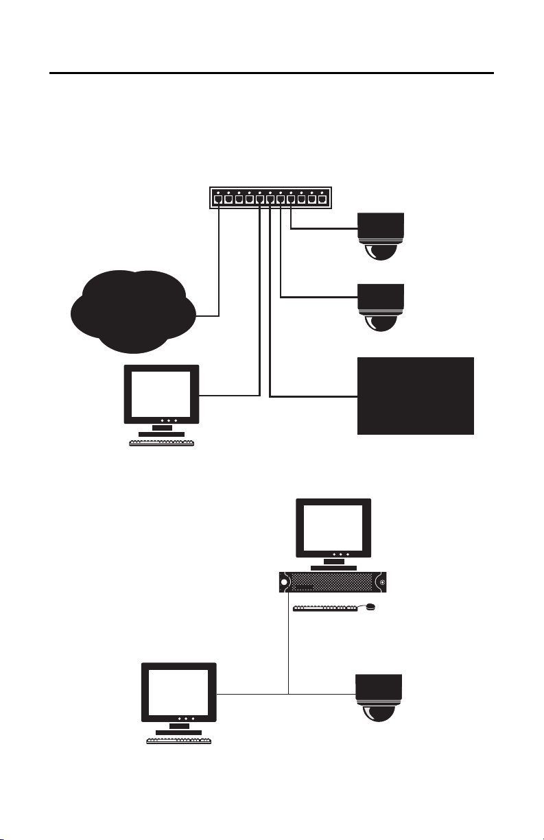
Basic System Configurations
TCP / IP / INTERNET
3rd PARTY
RECORDING SOLUTION
IMPORTANT NOTE. PLEASE READ. The network implementa
tions in this document are shown as
general representations only and are not intended to show detailed network topologies. Your actual
network will differ, requiring changes or perhaps additional network equipment to accommodate the
systems as illustrated. Please contact your local Pelco representative to discuss your specific
requirements.
CABLE MODEM ROUTER / SWITCH
WITH DHCP SERVER
NOTE: FOR A SECURE NETWORK,
PELCO RECOMMENDS THE IP110
CAMERA IS PLACED BEHIND A
FIREWALL.
IP110
TCP / IP / INTERNET
IP110
WEB
BROWSER
DHCP NETWORK
3rd PARTY
RECORDING SOLUTION
Figure 1. DHCP Network Example
ENDURA
WEB
BROWSER
IP110
Figure 2. Endura Network Example
10 C3432M-G (4/09)
Page 11
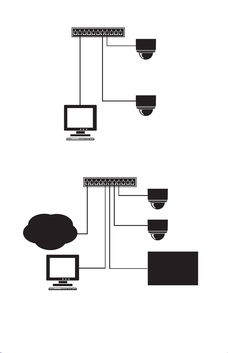
NETWORK SWITCH
TCP / IP / INTERNET
3rd PARTY
RECORDING SOLUTION
IP110
IF NOT DHCP, CAMERA IS ASSIGNED
DEFAULT IP ADDRESS 192.168.0.20 ON
NETMASK 255.255.255.0
NOTE: FOR A SECURE NETWORK,
PELCO RECOMMENDS THE IP110
CAMERA IS PLACED BEHIND A
FIREWALL.
TCP / IP / INTERNET
PRIVATE NETWORK
WEB
BROWSER
WEB
BROWSER
Figure 3. Private Network Example
CABLE MODEM ROUTER / SWITCH
(DHCP SERVER DISABLED)
IP110
IP110
IP110
RECORDING SOLUTION
CAMERA 1 FIXED BUT
UNIQUE IP ADDRESS,
SAME SUBNET MASK
AS COMPUTER
CAMERA 2 FIXED BUT
UNIQUE IP ADDRESS,
SAME SUBNET MASK
AS COMPUTER
3rd PARTY
STATIC NETWORK
(FIXED BUT UNIQUE IP ADDRESS
SAME SUBNET MASK AS CAMERAS)
Figure 4. Static Network Example
C3432M-G (4/09) 11
Page 12
Cover and Back Box Installation
The IP110 Series Camclosure integrated camera system mounts only to a surface. It can be wired through
the cover into a surface, electrical box, plaster ring, or through a side conduit opening.
flash mount adaptor ring is available. Refer to the IP110-F Flush Mount Adaptor Installation
NOTE: A
manual (C2238M) for installation instructions.
BASIC SURFACE INSTALLATION
1. Remove the two 8-32 x 0.375-inch Phillips pan head screws and washers (supplied) to separate the
cover from the back box.
2. Cut out the hole for the cable and wiring. Pull the cable a
then through the hole of the cover.
3. Attach the cover to the mounting surface (hardware not supplie
when installing the system outdoors.
4. Install the camera module into the back box before instal
camera module to access the mounting holes inside the back box (refer to Camera Module on
page 19 for more information).
5. Connect the cable and wires (refer to Wiring Tables on page 16 for information).
6. Reinstall the back box inside the cover. Use the two 8-32 x 0.375-inch Phillips pan head screws and
washers (removed
earlier) to secure the back box to the cover.
nd wires through the mounting surface and
d). Use stainless steel hardware
ling the back box into the cover. Rotate the
COVER
MOUNTING
SCREWS
(NOT SUPPLIED)
8-32 X 0.375-INCH
PHILLIPS PAN HEAD
SCREWS WITH WASHERS
12 C3432M-G (4/09)
(SUPPLIED)
Figure 5. Basic Su
rface Installation
BACK BOX
Page 13
4S ELECTRICAL BOX INSTALLATION
1. Attach an ICS110-AP adapter plate (not supplied) to a 4S electrical box. Use two 8-32 x 0.75-inch
Phillips flat head screws (supplied with both the IP110 and the adapter plate).
2. Remove the two 8-32 x 0.375-inch Phillips pan head screws and washers to separate the cover from
the back
box.
3. Pull the cable and wires into the cover.
4. Attach the cover to the adapter plate with four 8-32 x 0.375-inch Phillips pan head screws (supplied
with the ada
5. Install the camera module into the back box before instal
camera module to access the mounting holes inside the back box (refer to Camera Module on
page 19 for more information).
6. Connect the cable and wires (refer to Wiring Tables on page 16 for information).
7. Reinstall the back box inside the cover. Use the two 8-32 x 0.375-inch Phillips pan head screws and
washers (removed
pter plate). Use stainless steel hardware when installing the system outdoors.
ling the back box into the cover. Rotate the
earlier) to secure the back box to the cover.
4S STANDARD
ELECTRICAL BOX
CEILING/
WALL
8-32 X 0.75-INCH
PHILLIPS FLAT
HEAD SCREWS
(SUPPLIED)
8-32 X 0.375-INCH
PHILLIPS PAN HEAD
SCREWS WITH WASHERS
(SUPPLIED)
Figure 6. 4S Ele
C3432M-G (4/09) 13
ADAPTER PLATE
(ICS110-AP)
ctrical Box Installation
COVER
8-32 X 0.375-INCH
PHILLIPS PAN
HEAD SCREWS
(SUPPLIED WITH
ICS110-AP)
BACK BOX
Page 14
404 PLASTER RING INSTALLATION
1. Remove the two 8-32 x 0.375-inch Phillips pan head screws and washers (supplied) to separate the
cover from the back box.
2. Pull the cable and wires into the cover. Use three 6-32 x
(supplied) or two 8-32 x 0.75-inch Phillips pan head screws (supplied) to attach the cover to an
installed 404 plaster ring. Use stainless steel hardware when installing the system outdoors.
3. Install the camera module into the back box before instal
camera module to access the mounting holes inside the back box (refer to Camera Module on
page 19 for more information).
4. Connect the cable and wires (refer to Wiring Tables on page 16 for info
5. Reinstall the back box inside the cover. Use the two 8-32 x 0.375-inch Phillips pan head screws and
washers (removed
6-32 X 0.75-INCH
OR 8-32 X 0.75-INCH
HEAD SCREWS
earlier) to secure the back box to the cover.
CEILING/
WALL
404 PLASTER RING
(NOT SUPPLIED)
PHILLIPS PAN
(SUPPLIED)
0.75-inch Phillips pan head screws
ling the back box into the cover. Rotate the
rmation).
COVER
BACK BOX
8-32 X 0.375-INCH
PHILLIPS PAN HEAD
SCREWS WITH WASHERS
(SUPPLIED)
Figure 7. 404 Plaster Ring Installation
14 C3432M-G (4/09)
Page 15

SIDE CONDUIT INSTALLATION
1. Remove the two 8-32 x 0.375-inch Phillips pan head screws and washers (supplied) to separate the
cover from the back box.
2. Remove the conduit plug from the cover. Install a 0.7
(not supplied) into the conduit hole in the cover.
3. Attach the cover to the mounting surface (hardware not supplie
when installing the system outdoors.
4. Install the camera module into the back box before instal
camera module to access the mounting holes inside the back box (refer to Camera Module on
page 19 for more information).
5. Connect the cable and wires (refer to Wiring Tables on page 16 for information).
6. Reinstall the back box inside the cover. Use the two 8-32 x 0.375-inch Phillips pan head screws and
washers (removed
0.75-INCH CONDUIT
CONDUIT PLUG
earlier) to secure the back box to the cover.
CONNECTOR
REMOVE
5-inch (1.91 cm) threaded conduit connector
d). Use stainless steel hardware
ling the back box into the cover. Rotate the
COVER
BACK BOX
8-32 X 0.375-INCH
PHILLIPS PAN HEAD
SCREWS WITH WASHERS
C3432M-G (4/09) 15
(SUPPLIED)
Figure 8. Sid
e Conduit Installation
Page 16

Wiring Tables
8
8
1
1
CAT5 CABLE
Connect a Cat5 cable to the RJ-45 network connector. The 8-pin connector includes video and PoE for the
camera. PoE (IEEE 802.3af) injects power over the same cabling that carries the network data, eliminating
the need for a separate power supply. This simplifies the installation and operation of the camera without
any degradation of network performance.
NOTE: The IP110 Camclosure will autosense
Refer to Figure 9 for pin descriptions
1
2
3
4
5
6
7
8
and work with either a cross over cable or straight cable.
8
7
6
5
4
3
2
1
Pin Function
1TX+
2TX-
3RX+
4 PoE 1-2
5 PoE 1-2
6RX-
7 PoE 3-4
8 PoE 3-4
Figure 9. Cat5 Cable Pin Descriptions
16 C3432M-G (4/09)
Page 17

ALARM AND 24 VAC WIRES
+
_
Tab le B . Wire Descriptions
Wire Color Description
Black 24 VAC (use only if PoE is not connected)
Red 24 VAC (use only if PoE is not connected)
Blue Alarm In
Blue/White Alarm In, Return
Green Relay Out
Green/White Relay Out, Return
CONNECTING A RELAY DEVICE
The IP110 Camclosure has an output for triggering an external device. It supports both momentary and
continuous relay operation.
You can operate the relay interactively, during an active
certain events. Typical applications include activating a door, gate or lock, or switching on lights or other
electrical devices.
WARNING: Do not exceed the maximum rating of 12 VDC, 0.15 A.
Figure 10 shows how to wire the relay with its power source to the Camclosure.
CONNECTING A RELAY DEVICE
(CONNECTION EXAMPLE)
connection, or automatically to coincide with
DC
GREEN WIRE
GREEN / WHITE WIRE
Figure 10. Relay Wiring
NOTE: The green/white wire is internally connected to the Camclosure chassis. Any connected signaling
device should remain floating with respect to the Camclosure chassis; otherwise damage could result.
C3432M-G (4/09) 17
Page 18

CONNECTING ALARMS
The IP110 Camclosure provides an alarm input for external signaling devices, such as door contacts or
motion detectors. Both normally open and normally closed devices are supported. The IP110 Series
Camclosure supports supervised and unsupervised alarms.
Figure 11 shows how to wire the IP110 Camclosure to an alarm.
ALARM RETURN: BLACK / WHITE WIRE
ALARM: BLACK WIRE
Figure 11. Unsupervised Alarm Input Wiring
NOTE: The black wire is internally connected to the Camclosure chassis. Do not connect directly to any
potential except chassis ground.
18 C3432M-G (4/09)
Page 19

Camera Module
The IP110 Series Camclosure camera module includes the camera, camera bracket, and heater board.
To perform most camera adjustments, you must remove the module from the back box.
Use the following instructions to install or remove the c
WARNING: Heater elements could be hot! When camera power is on, use caution when adjusting
the camera. This applies to all models.
CAMERA ORIENTATION
The camera module is configured for ceiling mounting at the factory. For wall mounting, you must change
the camera orientation or the video image will be upside down.
To change the camera orientation (refer to Figure 12):
1. Remove the camera module from the back box (if necessary).
2. Remove the tilt adjustment screw and lock washer from each side of the camera.
3. Carefully rotate the camera one-half turn.
4. Reinstall the tilt adjustment screw and lock washer on each side of the camera.
5. Verify the camera orientation.
amera module.
Make sure the wiring harness does not bind.
CEILING MOUNT (DEFAULT)
TILT ADJUSTMENT
SCREW AND
LOCK WASHER
BOTTOM
OF CAMERA
TILT ADJUSTMENT
SCREW AND
LOCK WASHER
Figure 12. Camera Orientation
WALL MOUNT
TOP OF
CAMERA
C3432M-G (4/09) 19
Page 20

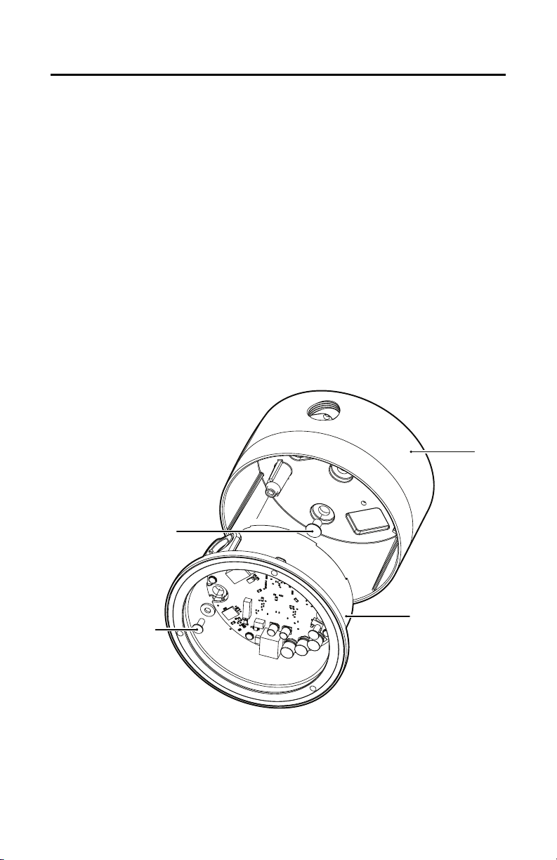
MODULE INSTALLATION
To install the camera module into the back box:
1. Plug the camera (10-pin), heater board (4-pin), and
to Figure 13).
HEATER
CONNECTOR
Figure 13. Back Box Connectors
2. Make sure the tabs on the camera bracket and the service connector are pointing out of the
enclosure and away from the ceiling or wall.
3. Gently squeeze the bracket, place it against the groove inside the back box, and then gently release
fer to Figure 14).
(re
service (3-pin) connectors into the back box (refer
SERVICE
CONNECTOR
CAMERA
CONNECTOR
BRACKET
Figure 14. Camera Module Bracket
20 C3432M-G (4/09)
Page 21

Camera Adjustments
To perform camera adjustments:
1. Make sure the camera and service connectors are connected to the board inside the back box.
You
may have to remove the camera module from the back box.
2. Connect a monitor to the service connector (refer to Service Connector on page 32). Turn on the
monitor.
3. Turn on the camera. The camera will start the following configuration process:
• The green LED inside the back box flashes five times per second for approximately two
minutes, or until the PC or server recognizes the mini dome.
• If the dome is not connected to a Dynamic Host Configuration Protocol (DHCP) PC/server, the
green LED will flash for approximately four minutes before the camera switches to an
automated private IP addressing mode.
NOTE: If the IP110 is connected to a DHCP network, the server will automatically assign an
IP
address to the camera. If the IP110 is connected to static network, the IP address
192.168.0.20 on netmask 255.255.255.0 is automatically assigned to the camera. If the camera
has an older software version installed (versions 01.00.0038 and older for IP110 and versions
01.00.0018 for IP3701H), the network will automatically cycle through the IP address range of
169.254.200.0 through 169.254.200.255, on netmask 255.255.255.0. The first available address
located will be assigned to the IP110. If the network cannot find an open address in the default
range, contact your network administrator.
4. To adjust the camera, you will need a miniature trimpot adjustment tool with a 0.05-inch (1.27 mm)
blade. Suggested tools include a miniature flat-tip screwdriver, a Philmore trimpot tool (#63-6808),
and the Philmore 10-piece tool set (#63-910).
5. Refer to the following sections for detailed information on camera adjustments:
• Varifocal Lens Zoom and Focus Adjustments on page 22
• DN/CH Series Adjustments on page 24
• DW/CW Series (Wide Dynamic Range) Adjustments on page 27
6. After you have adjusted the unit, reinstall the camera module into the back box, and then install the
trim ring, bubble, and dome liner (refer to
page 31).
C3432M-G (4/09) 21
Page 22

VARIFOCAL LENS ZOOM AND FOCUS ADJUSTMENTS
NOTE: You will need a miniature Phillips or flat-tip screwdriver to loosen and tighten the locking screws.
To adjust the field of view:
1. Loosen the zoom locking screw (refer to Figure 15).
2. Turn the zoom adjustment ring clockwise or counterclockwise to s
3. Tighten the zoom locking screw.
FOCUS
ZOOM
elect the field of view.
Figure 15. Location of Zoom and Focus Locking Scr
22 C3432M-G (4/09)
ews
Page 23

To adjust the focus:
1. Loosen the focus locking screw.
2. Position the inverted dome approximately 0.125 inch (3.175 mm) from the front of the lens. Make
sure that the len
s and the dome are centered (refer to Figure 16).
3. Turn the focus locking screw clockwise or counterclockwise to adjust the focus.
4. When the optimal focus is reached, tighten the focus locking screw.
ZOOM
FOCUS
0.125 INCH (3.175 mm)
CENTER BUBBLE
WITH LENS
Figure 16. Adjusting the Focus
C3432M-G (4/09) 23
Page 24

DN/CH SERIES ADJUSTMENTS
Refer to Figure 17 to adjust the IP110-DN or IP110-CH model.
Figure 17. Adjusting the IP110-DN/CH Series Camclosure
SWITCH SETTINGS
Locate the DIP switch. Then set the switches for your installation.
SW4-1: Auto Gain Control
The automatic gain control (AGC) adjusts the image automatically to compensate for changes in light
levels.
Set SW4-1 to ON to enable AGC. Set it to OFF to
disable AGC. The default setting is ON.
SW4-2: Backlight Compensation
The backlight compensation (BLC) feature compensates for backlit scenes by enhancing objects in the
center of the scene.
Set SW4-2 to ON to enable BLC. Use this setting if a b
center of the picture appears dark or as a silhouette.
Set it to OFF to disable backlight compensation.
right backlight is present and the subject in the
This is the default setting.
SW4-3: N/A
24 C3432M-G (4/09)
Page 25

SW4-4: Flickerless
In certain lighting conditions, a flicker in the light source may affect camera operation. Flickering can be
caused by a number of conditions, including the quality of the source power and the age and type of
fluorescent bulbs and ballasts.
Set SW4-4 to ON to enable flickerless operation. The camera will remove the effects of flickering when
present. The shutter speed will be set to 1/120 (NTSC) or 1/100 (PAL).
Set it to OFF to disable flickerless operation. This is the default setting.
NOTE: If you enable flickerless operation, you should use AC line lock for best results.
SW4-5: Auto White Balance/Manual White Balance
Auto white balance (AWB) is enabled by default (OFF).
To manually set and lock the white balance:
1. Set SW4-5 to OFF.
2. Hold a white background in front of the lens until the video shows all white.
3. While holding the background in place, set SW4-5 to ON. A blue blinking block appears on the video
image for a few seconds. When the block changes to solid green, the manual white balance (MWB)
process is complete.
SW4-6: Reserved
Do not change SW4-6 from its factory setting. SW4-6 must be set to OFF for Varifocal models; it must be
set to ON for fixed iris lenses.
BLEMISH DETECTION
If small white or color spots appear in the video image, one or more pixels on the camera imager may be
defective. (This condition is common for both CCD and CMOS imagers.)
DN and CH Series cameras with auto iris lenses automatically detect and correct defective pixels during
startup. Video turns on, then off, and then on again. If white or color spots still appear, you can correct the
defective pixels manually.
CH Series cameras with fixed iris lenses do not automatically detect and correct defective pixels. You can
correct the defective pixels manually.
To manually correct defective pixels:
1. Cover the lens completely. Make sure no light can enter the lens.
NOTE: The mechanical iris lens aperture does not completely block the light.
2. Press and hold button SW3 for one second. The camera will find and correct defective pixels.
NOTE: Any defective pixels that cannot be completely corrected may still appear.
3. Release button SW3.
4. Uncover the lens for normal camera operation.
C3432M-G (4/09) 25
Page 26

DAY/NIGHT OPERATION
NOTE: This section only applies to DN model cameras.
DN model cameras regularly check the brightness level of t
between day (color) and night (black-white) operation.
Actual brightness threshold levels are affected by camera angle, amount of zoom, field of view, lens, and
lighting. The switching process lasts from seven to 10 seconds.
type of
Figure 20 and Table C show how the camera switches between color and black-white operation.
MODE
3.0 lux
COLOR
he field of view to determine when to switch
MODE
COLOR
B-W
MODE
1.5 lux
B-W
FALLING LIGHT LEVEL
Figure 18. DN Models Threshold Switching L
Tab le C . DN
Models Switching Thresholds
RISING LIGHT LEVEL
MODE
evels
Color to B-W 1.5 lux ±1.0 lux
B-W to Color 3.0 lux ±1.0 lux
NOTE: These switching thresholds are approximate. Use the thresholds in Table C as a guide when
installing the unit.
26 C3432M-G (4/09)
Page 27

DW/CW SERIES (WIDE DYNAMIC RANGE) ADJUSTMENTS
Refer to Figure 19 to adjust the IP110-DW or IP110-CW model.
SW1
DEFAULT SWITCH POSITION
Figure 19. Adjusting the IP110-DW/CW Series Camclosure
R7
SWITCH SETTINGS
Locate the DIP switch. Then set the switches for your installation.
SW1-1: Video Format
Set SW1-1 to ON for NTSC. Set it to OFF for PAL. The default setting is ON.
SW1-2: N/A
SW1-3: Interlaced Scanning/Progressive Scanning
Interlaced scanning is the standard for analog recording installations. Each frame contains one odd and
one even field, each processed separately.
Progressive scanning is better for digital recording installations.
which results in less blurring and cleaner digital conversion. It also saves storage space on digital video
recorders.
Set SW1-3 to ON to select interlaced scanning.
Set it to OFF to select progressive scanning. The default setting is ON.
Each frame is processed as a whole,
C3432M-G (4/09) 27
Page 28

SW1-4: Auto White Balance/Manual White Balance
Auto white balance (AWB) is enabled by default (ON).
To manually set and lock the white balance:
1. Set SW1-4 to ON.
2. Hold a white background in front of the lens until the video shows all white.
3. While holding the background in place, set SW1-4 to OFF. A green block and a white block alternate
briefly on the video image until the manual white balance (MWB) process is complete.
SW1-5: Fluorescent/General
Enable this option to adjust the camera for best operation under fluorescent lighting.
Set SW1-5 to OFF for fluorescent lighting. Set it to ON for general lighting. The default setting is ON.
NOTE: If you use fluorescent operation, you should use AC line lock for best results.
SW1-6: General/Maximum Wide Dynamic Range
Maximum wide dynamic range (WDR) supports about 36 dB of additional dynamic range over a standard
camera. Use it for installations that require the maximum WDR.
General WDR supports about 20 dB of additional dynamic range over a standard camera. Use it for
installations that do not require the maximum WDR.
Set SW1-6 to ON to select maximum WDR. Set it to OFF to select general WDR. The default setting is ON.
SW1-7: Digital Slow Shutter
The default shutter speed for NTSC is 30 frames per second (fps). It is 25 fps for PAL. This is also known as
SENS 2X.
You can decrease the shutter speed to 7.5 fps (NTSC) or 6.25 fps (PAL). This is known as SENS 8X, which
improves low light sensitivity.
Set SW1-7 to ON to select SENS 2X. Set it to OFF to select SENS 8X. The default setting is ON.
SW1-8: Day/Night Operation (DW models only)
NOTE: On CW models, SW1-8 is unused and does not affect camera operation.
DW model cameras regularly check the brightness level of the field of view to determine when to switch
between day (color) and night (black-white) operation. Use SW1-8 to set the general light levels at which
the camera will automatically switch.
Set SW1-8 to ON (dark) to use standard thresholds to switch between color and black-white operation.
This is the default.
Set it to OFF (dusk) to use higher light thresholds to switch between color and black-white operation.
Actual brightness threshold levels are affected by camera angle, amount of zoom, field of view, lens, and
type of lighting. The switching process lasts from seven to 10 seconds.
28 C3432M-G (4/09)
Page 29

Figure 18 and Table D show how the camera switches between color and black-white operation for each
setting.
MODE
COLOR
B-W
MODE
RISING LIGHT LEVEL
MODE
COLOR
3.0 lux
FALLING LIGHT LEVEL
1.0 lux
B-W
MODE
MODE
COLOR
B-W
MODE
RISING LIGHT LEVEL
FALLING LIGHT LEVEL
MODE
COLOR
B-W
MODE
7.0 lux
4.0 lux
DARK
DUSK
Figure 20. DW Models Threshold Switching Levels
Table D. DW Models Switching Thresholds
Dark (ON) Dusk (OFF)
Color to B-W 1.0 lux 4.0 lux
B-W to Color 3.0 lux 7.0 lux
NOTE: These switching thresholds are approximate and were measured using a 3.0 to 9.5 mm lens at
f/1.0. Use the thresholds in Tab l e D as a guide when installing the unit.
AUTO IRIS LEVEL ADJUSTMENT
The electronics of the IP110-DW and IP110-CW Series Camclosures automatically adjust the camera to
the auto iris. Auto iris level adjustments are not necessary.
C3432M-G (4/09) 29
Page 30

Camera Positioning
Manually rotate and tilt the camera module to position the camera, and then tighten the tilt screws
(axis 1 in Figure 21).
NOTE: Do not over-rotate the module. Excessively turning the module in
damage to the wiring.
one direction could result in
ì Tilt 80° (20° to 100°) î Pan 360° ï Rotation 360°
Figure 21. Positioning the Camera
30 C3432M-G (4/09)
Page 31

Install Dome and Trim Ring
1. To adjust the dome liner (refer to Figure 22):
a. Align the screw holes in the trim ring with those in the back box to identify the proper dome
liner positio
b. Loosen the three Phillips screws located in the trim ring.
c. Insert the blade of a standard screwdriver in one of the adjustment groo
liner to position the viewing window over the camera lens.
d. Tighten the three Phillips screws to lock the dome liner in
2. Align the screw holes in the trim ring with those in the back box.
3. Tighten the tamper-resistant screws through the trim ring
screwdriver bit (supplied).
n.
ADJUSTMENT
GROOVE
LINER
LOOSEN SCREWS
Figure 22. Dome Liner Adjustment
ves. Rotate the dome
place.
into the back box. Use the 1/8-inch hollow
C3432M-G (4/09) 31
Page 32

Service Connector
The IP110 Series Camclosure integrated camera system includes a service connector that outputs camera
vide
o. Use it at the installation site to set up the field of view and focus the camera.
SERVICE
CONNECTOR
Figure 23. Service Connector
Pelco offers two optional items (CST150 and ICS-SC) that plug directly into the service connector. Before
using either option, you must loosen the tamper-resistant screws to remove the trim ring from the back
box. Use the 1/8-inch hollow screwdriver bit (supplied).
The CST150 has a 3-foot (0.9 m) cable and microdisplay fo
connector and view the video.
NOTE: The three buttons on the CST150 are not used with the IP110 Series Camclosure.
The ICS-SC has a 4-foot (1.2 m) cable with a servic
connector into the unit. Then connect the other end to any standard BNC (VIDEO IN) connector on a
monitor.
To assemble a longer service cable for the Camclosure
items from a local electronics supply store:
Qty Description
1 2.5 mm monaural headphone plug
1 CPM 88 miniature coaxial connector
1 RG174/U coaxial cable
To assemble the cable:
1. Attach the CPM 88 miniature coaxial connector to one
supplied with the miniature coaxial connector.
2. Attach the 2.5 mm monaural plug to the other end of the coaxial cable (refer to Figure 24):
a. Remove the support sleeve from the plug.
b. Slip the support sleeve over the end of the cable.
c. Prepare the cable.
r viewing camera video. Plug it into the service
e connector and a BNC connector. Plug the service
integrated camera system, purchase the following
end of the cable. Follow the directions
32 C3432M-G (4/09)
Page 33

d. Solder the center connector of the cable to the center pin of the plug.
e. Thread the braid of the cable through the hole in the crimp pin.
f. Solder the braid to the top of the crimp pin.
g. Crimp the end of the crimp pin around the cable.
h. Reassemble the support sleeve and the plug.
CENTER CONDUCTOR
COAXIAL
CABLE
BRAID (SHIELD)
2.5 MM MONAURAL
HEADPHONE PLUG
Figure 24. Attaching the 2.5 mm Monaural Headphone Plug
C3432M-G (4/09) 33
Page 34

Reset Button
Use the reset button located on the board inside the back box to access the following modes described in
Table E.
Table E. Reset Button Modes and Descriptions
Mode Function Unit Status Indicator Light
Configuration Starts the reset LED
Reboot Restarts the unit. Flashes green and red simultaneously, when entering
Reset Resets the unit to factory
Cancel Cancels any configuration
To access one of these modes:
1. Press and hold the reset button. The unit starts cycling through the modes; hold the button for four
seconds
current mode (refer to the table above).
2. When the color of the desired mode appears, release the button.
NOTES:
• If there is no configuration activity for 15 minutes, th
mode.
• The LED is not lit during normal operation.
selection sequence.
default settings, and then
restarts the unit.
or reset action.
to access (cycle through) each mode. The unit status indicator flashes the color for the
Flashes green.
this mode. The LED then flashes green when mode is
selected and during the reboot.
Flashes red when entering this mode. Flashes red
when the mode is selected, and then flashes green
when the camera restarts. The camera is off line
during reset mode.
No light.
e camera will automatically exit the reset
RESET
BUTTON
RED / GREEN LEDS
Figure 25. Location of Reset Button and LEDs
34 C3432M-G (4/09)
Page 35

Troubleshooting
If the following instructions fail to solve your problem, contact Pelco Product Support at 1-800-289-9100
(USA and Canada) or +1-559-292-1981 (international) for assistance. You should have the serial number
from the product label available.
Do not try to repair the unit yourself. Opening it immediately voids any warranty. Leave maintenance and
repairs to qualified technical personnel. Exchange the defective unit and return it for repair.
Tab le F. Troubleshooting the IP110 Series (1 of 3)
Problem Possible Cause Suggested Remedy
No video PoE power issue • Check Cat5 cable connection.
• Verify PoE is enabled.
• Disconnect the Cat5 cable from the PoE, and then
reconnect the cable. Check the LED inside the back
box to verify that it is flashing green, indicating the
camera has power.
Power issue (24 VAC) • Check the 24 VAC power supply connection.
• Disconnect the network cable, and then reconnect it
to the camera. Check the LED inside the back box to
verify that it is flashing green, indicating the camera
has power.
Image too dark/
black image
Network connectivity
issues
Defective camera • Check the camera’s 10-pin connector inside the back
Installation error • Make sure the lens cover in not installed.
• Check network cable connections.
• Disconnect the network cable, and then reconnect it
to the camera. Check the LED inside the back box to
verify that it is flashing green.
• Replace network cable with new cable.
box to make sure it is connected.
• Use a service connector to check camera operation.
Connect one end of the service connector to the
service connector input inside the back box. Then
connect the other end of the service connector to a
monitor.
• Replace camera module with new camera.
• Make sure camera is not located in an environment
with zero light.
• Use a service connector to check camera operation.
Connect one end of the service connector to the
service connector input inside the back box. Then
connect the other end of the service connector to a
monitor.
• Replace camera module with new camera.
C3432M-G (4/09) 35
Page 36

Tab le F. Troubleshooting the IP110 Series (2 of 3)
Problem Possible Cause Suggested Remedy
Image too light Installation error • Check DIP switch settings.
• Use a service connector to check camera operation.
Connect one end of the service connector to the
service connector input inside the back box. Then
connect the other end of the service connector to a
monitor.
• Replace camera module with new camera.
Image only
displayed in
black and white
Color level setting • Check DIP switch settings.
• Use a service connector to check camera operation.
Connect one end of the service connector to the
service connector input inside the back box. Then
connect the other end of the service connector to a
monitor.
• Replace camera module with new camera.
IR cut filter setting • Check DIP switch settings.
• Use a service connector to check camera operation.
Connect one end of the service connector to the
service connector input inside the back box. Then
connect the other end of the service connector to a
monitor.
• Add direct light to camera. Wait 30 seconds to see if
IR cut filter is functioning.
• Replace camera module with new camera.
Flickering in
image
Flickerless setting • Check DIP switch settings.
• Check power supply specifications.
• Replace camera module with new camera.
Camera not
discovered
No camera power Verify the camera is powered correctly with PoE or with
24 VAC. Confirm power consumption with Web
interface of PoE-capable switch or through blinking
green LED during camera power up.
Network conflict • Verify the camera is physically connected to the
same network as the PC running the Device Utility.
• The utility will not work on a network that blocks
multicast traffic.
• Confirm that the green LED flashes when power is
applied to the camera, indicating network
connectivity.
36 C3432M-G (4/09)
Page 37

Tab le F. Troubleshooting the IP110 Series (3 of 3)
Problem Possible Cause Suggested Remedy
Network not
working
Faulty cable
connection
Incorrect serial device
configuration
Check all cable connections and ensure all plugs are
properly plugged in.
A hub will not work with the available network
bandwidth shared across all ports. Use a Fast Ethernet
switch, Gigabit Ethernet switch, or a cable modem
router with an n-Port switch.
Network connectivity
Contact your network administrator.
issues
Unable to sync
to an Endura
®
system manager
or NTP server
after changing
networks
Network connectivity
issues
• Disconnect the power cable (either PoE or 24 VAC)
and then reconnect it to the camera. Power is
indicated by the LED. The LED will flash (green) five
times per second for approximately two minutes if
the camera has power.
• Reset the camera’s factory defaults (refer to Reset
Button on page 34).
C3432M-G (4/09) 37
Page 38

Specifications
GENERAL
Pan/Tilt Adjustment Manual
Pan 360°
Tilt 80° (20° to 100° range)
Rotation 360°
Construction Aluminum with steel camera mounting bracket and polycarbonate dome
Impact IP110 is a rugged product that exceeds an IK10++ rating of Standard
Cable Entry One 0.75-inch (1.91 cm) NPT threaded opening on side; two 0.75-inch
Finish Gray polyester powder coat
Light Attenuation
Smoked f/1.5 light loss
Clear Zero light loss
Unit Weight 2.2 lb (1.0 kg)
ELECTRICAL
Ports RJ-45 connector for 100Base-TX
Cabling Type Cat5 or better for 100Base-TX
Input Voltage 24 VAC (18-36) or PoE (IEEE802.3af)
Power Consumption <7.5 W, <13 W with heaters
Alarm Input 10 VDC maximum, 5mA maximum
Alarm Output 0 to 15 VDC maximum, 75 mA maximum
Service Connector Internal to housing 3-connector, 2.5 mm connector providing NTSC/PAL
EN62262 and can withstand up to 100J in a vertical impact
(1.91 cm) openings on NEMA cover
Auto MDI/MDI-X
Autonegotiate/Manual setting
24VAC: <0.5 A, <0.9 A with heaters
video outputs
38 C3432M-G (4/09)
Page 39

VIDEO
Signal System NTSC or PAL
Compression MPEG-4, MJPEG in Web viewing mode
Video Streams 3, simultaneous
Video Resolutions NTSC PAL
4CIF 704 x 480 704 x 576
2CIF 704 x 240 704 x 288
CIF 352 x 240 352 x 288
QCIF 176 x 120 176 x 144
Bit Rate Configurable 20 kbps to 2 Mbps per stream, implements EnduraView
™
Video Access form
Web Browser Camera live view for up to 10 video sources
Users 10 simultaneous users, unlimited number of users using multicast
Minimum Web Browser
Requirements PC (Pentium® 4 microprocessor, 1.6 GHz) with Windows® 98,
Windows 2000, Windows XP (or later) or Mac
®
OS X 10.3.9 (or later)
RAM 512 MB
Ethernet Card 100 Megabits
Web Browser Internet Explorer 5.5 (or later) or Firefox 1.5 (or later)
Screen Resolution 1024 x 768 pixels or higher, 16- or 32-bit pixel color resolution
ENVIRONMENTAL
Environment Low temperature, indoor/outdoor
Operating Temperature -50° to 122°F (-46° to 50°C); de-ices to 25°F (-4°C)
Thermostat Operation Heater is thermostatically controlled to activate at <41°F (<5°C)
CAMERA
Service Connector 3-conductor, 2.5 mm connector for video output to optional ICS-SC cable
Imaging Device 1/3-inch imager
Picture Elements NTSCPA L
DW/CW 720 (H) x 540 (V) 720 (H) x 540 (V)
DN/CH 768 (H) x 494 (V) 752 (H) x 582 (V)
Dynamic Range
DW/CW 102 dB typical/120 dB maximum
Signal System NTSC or PAL
Scanning System
DW/CW 2:1 interlace/progressive scanning (DIP switch selectable)
DN/CH 2:1 interlace
Synchronization Internal
Electronic Shutter Range Auto (1/15~1/22,000)
C3432M-G (4/09) 39
Page 40

LENS
Type Varifocal with auto iris
Focal Length 3.0~9.5 mm
Format Size 1/3-inch
Operation
Iris Auto (DC drive)
Focus Manual
Zoom Manual
(Design and product specifications subject to change without notice.)
9.0~22.0 mm
Ø 5.50
(13.97)
3.63
(9.22)
Ø 3.79
(9.63)
NOTE: VALUES IN PARENTHESES ARE CENTIMETERS; ALL OTHERS ARE INCHES.
3.03
(7.70)
5.28
(13.41)
40 C3432M-G (4/09)
Page 41

C3432M-G (4/09) 41
Page 42

REVISION HISTORY
Manual # Date Comments
C3432M 3/07 Original version.
C3432M-A 5/07 Cable harnesses modified per ECO 07-17470. Added picture elements to specifications.
C3432M-B 8/07 Added FCC Class B and revised DIP switch setting adjustments.
C3434M-C 11/07 Revised figures 20 and 22.
C3432M-D 1/08 Added Open Source Software Notice.
C3432M-E 4/08 Removed references to JRE per CN21186.
C3432M-F 6/08 Changed static IP address to new default 192.168.0.20 per CN21529.
C3432M-G 4/09 Added a lens focus procedure to Cam
unsupervised alarms information from Connecting Alarms. Added adaptor ring note to Cover
and Back Box Installation, and added an input voltage note and impact statement to
Specifications.
Pelco, the Pelco logo, Camclosure, Digital Se ntry, Endura, Esprit, ExSite, Genex, Intelli-M, Legacy, and Spectra are registered trad emarks of Pelco, Inc.
Spectra III is a trademark of Pelco, Inc.
DLP is a registered trademark of Texas Instruments Incorporated.
All product names and services identified t hroughout this document are trademarks or registered trademarks of their re spective companies.
The absence of a trademark or registered tr ademark from this document does not constitute a waiver of intellectual property rights.
© Copyright 2009, Pelco, Inc. All rights rese rved.
42 C3432M-G (4/09)
era Adjustments. Removed supervised and
Page 43

PRODUCT WARRANTY AND RETURN INFORMATION
WARRANTY
Pelco will repair or replace, without charge, an y merchandise proved defective in material or workmanship for a period of one year after the date of
shipment.
Exceptions to this warranty are as noted below:
• Five years:
– Fiber optic products
– TW3000 Series unshielded twisted pair (UTP) transmission pro ducts
– CC3701H-2, CC3701H-2X, CC3751H-2, CC3651H-2X, MC3651H-2, and MC3651H-2X camera models
• Three years:
– Pelco-branded fixed camera models (CCC1390H Series, C10DN Series, C10CH Series, an d IP3701H Series)
– EH1500 Series enclosures
®
– Spectra
IV products (including Spectra IV IP)
– Camclosure
– DX Series digital video recorders, DVR5100 Series digital video recorders, Digital Sent ry
– Endura
– Genex® Series products (multiplexers, server, and keyboard)
– PMCL200/300/400 Series LCD monitors
• Two years:
– Standard varifocal, fixed focal, and mot orized zoom lenses.
– DF5/DF8 Series fixed dome products
– Legacy® Series integrated positioning systems
– Spectra III™, Spectra Mini, Spectra Mini IP, Esprit®, ExSite®, and PS20 scanners, including when u sed in continuous motion applications.
– Esprit Ti and TI2500 Series thermal imaging products
– Esprit and WW5700 Series window wiper (excludi ng wiper blades).
– CM6700/CM6800/CM9700 Series matrix
– Digital Light Processing (DLP®) displays (except lamp and color wheel). The lamp and color wheel will be covered for a period of 90 days.
– Intelli-M
•One year:
– Video cassette recorders (VCRs), except video heads. Video heads will be covered for a period of six months.
• Six months:
– All pan and tilts, scanners, or preset lenses used in contin uous motion applications (preset scan, tour, and auto scan modes).
Pelco will warrant all replacement parts and repairs for 90 days from the date of Pelco shipment. All goods requiring warranty repair shall be sent
freight prepaid to a Pelco designated locatio n. Repairs made necessary by reason of misuse, alteration, normal wear, or accident are no t covered under
this warranty.
Pelco assumes no risk and shall be subject to no li ability for damages or loss resulting from the specific use or application made of the Products.
Pelco’s liability for any claim, whether based on breach of contract, negligence, infringement of any rights of any party or product liability, relating to
the Products shall not exceed the price paid by the Dealer to Pelco for such Products. In no event will Pelco be liable for any special, incidental, or
consequential damages (including loss of use, loss of profit, and claims of third parties) however caused, whether by the negligence of Pelco or
otherwise.
The above warranty provides the Dealer with spe cific legal rights. The Dealer may also have additional right s, which are subject to variation from state
to state.
If a warranty repair is required, the Dealer must contact Pelco at (800 ) 289-9100 or (559) 292-1981 to obtain a Repair Authorization number (RA), and
provide the following information:
1. Model and serial number
2. Date of shipment, P.O. number, sales order number, or Pelco invoice number
3. Details of the defect or problem
If there is a dispute regarding the warranty of a product that does not fall un der the warranty conditions stated above, please include a written
explanation with the product wh en returned.
Method of return shipment shall be the same or equal to the method by which the item was received by Pelco.
RETURNS
To expedite parts returned for repair or credit, please call Pelco at (800) 289-9100 or (559) 292-1981 to obtain an authorization number (CA number if
returned for credit, and RA number if returned for repair) and designated return location.
All merchandise returned for credit may be subject to a 20 percent restocking and refurbishing charge.
Goods returned for repair or credit should be clearly identified with the assigned CA or RA number and freight should be prepaid
®
Series (IS, ICS, IP) integrated camera systems
recorders, and NVR300 Series network video r ecorders
®
Series distributed network-based video pro ducts
The air filter is not covered unde r warranty.
®
eIDC controllers
®
Series hardware products, DVX Series digital vide o
12-23-08
Page 44

www.pelco.com
Pelco, Inc. Worldwide Headquarters 3500 Pelco Way Clovis, California 93612 USA
USA & Canada Tel (800) 289-9100 Fax (800) 289-9150
International Tel +1 (559) 292-1981 Fax +1 (559) 348-1120
 Loading...