


Optera™ IMM-DF5 Series Camera Adapter Kit
Important Safety Instructions
Prior to installation and use of this product, the following warnings should be observed:
1. Installation and servicing should only be done by qua
INSTALLATION MANUAL
C2287M (5/15)
lified service personnel and conform to all local codes.
2. Installation shall be done in ac
3. Use only installation methods and materials capable of supporting four times the maximum specified load.
cordance with all local and national electrical and mechanical codes utilizing only approved materials.
Description
The IMM-DF5 Series camera adapter kit is designed to install Optera™ IMM Series cameras inside DF5 Series fixed mount back boxes. The
camera adapter kit is compatible with in-ceiling mount models.
Adapter Kit and Dome Compatibility
The following DF5 Series domes are compatible with the IMM-DF5 Series camera adapter kit.
•DF5-0
•DF5-1
•DF5-2
•DF5-3
The IMM-DF5 Series camera adapter kit cannot be used with the DF5-0F, DF5S-0, and DF5S-1 Series dome models.
NOTE:
Parts List
Qty Description
1 IMM-DF5 Series camera adapter
1 DF5 in-ceiling adapter plate
3 8-32 Hex nut
1 1/4-20 x 1/2-inch Hex cap screw
1 1/4-inch split lock washer
1 1/4-inch flat washer
1 IMM-DF5 Series Installation manual
2 6-32 x 1/2-inch pan head, Phillips screw (optional; for use with PoE installations only)
2 #6 lock washer (optional; for use with PoE installations only)
User-Supplied Parts List
Qty Description
1 PoE+ injector (optional)
Product Overview
1
3
5
6
4
7
2
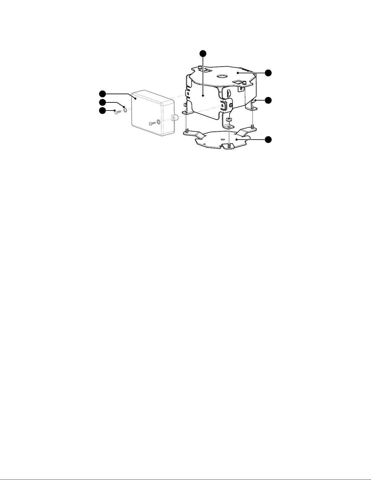
Figure 1. IMM Series Camera Adapter Kit Assembly
ì IMM-DF5 Series Camera Adapter Kit ó #6 Lock Washer
î 8-32 Hex Nut r PoE+ Injector
(optional, not supplied))
ï DF5 In-Ceiling Adapter Plate s PoE Injector Mount Bracket
ñ 6-32 x 1/2-Inch Pan Head,
Phillips Screw
2 C2287M (5/15)

Installing the Camera Adapter Kit
1. Ensure that the mounting surface is capable of supporting the full load of the IMM-DF5 Series camera adapter kit and IMM Series camera.
The camera adapter kit weighs 0.34 kg (0.75 lb).
2. Remove the lower dome assembly from the back box:
a. Locate one of the two small indentations along the trim ring between the Pelco logo and the ceiling tile. The bubble and trim ring fit
together as one piece called the lower dome, and they are removed as one piece.
b. Use a small flat head screwdriver and gently pry the lower dome away from the back box.
c. Gently pry the clip on the end of the trim ring leash from the hole on the lip of the back box. Set aside the dome for re-installation
later.
d. If your lower dome assembly has a liner, this will need to be removed by unscrewing the two fasteners and removing the retaining
clips.
3. Remove the existing camera and all mounting brackets from inside the housing. The mounting assembly and camera should be disposed of
according to the environmental standards in your area.
4. (If applicable) Pull the Cat5/Cat5e/Cat6 cable and the 24 AWG, 8-wire multiconductor cable (if using alarm, relays, and/or line-in and lineout audio) through the back box.
5. Attach the DF5 in-ceiling adapter plate (supplied) to the back box using the 1/4-inch flat washer, 1/4-inch split lock washer, and 1/4-20 x
1/2-inch Hex cap screw (all supplied).
6. (Optional) Attach the POE+ injector (not supplied) to the PoE injector mounting bracket using the 6-32 x 1/2-inch pan head Phillips screw
(supplied) and the #6 lock washer (supplied). Then connect the Cat5/Cat5e/Cat6 cable to the PoE+ injector.
7. Attach the IMM-DF5 Series camera adapter (supplied) to the DF5 in-ceiling adapter plate using the three 8-32 Hex nuts (supplied).
8. Install the IMM Series camera (refer to the IMM Series Installation manual for more information).
Installing the Lower Dome
1. Snap the clip on the end of the trim ring leash into the hole on the lip of the back.
2. Align the snaps on the trim ring with the mounting screws on the back box.
3. Snap the trim ring into the plastic snap washers on the mounting screws.
C2287M (5/15) 3

WARRANTY STATEMENT
For information about Pelco’s product warranty and thereto related information, refer to www.pelco.com/warranty.
Pelco, the Pelco logo, and other trademarks associa ted with Pelco products referred to in this publication are trademarks of Pelco, Inc. or its affilia tes. © Copyright 2015, Pelco, Inc.
ONVIF and the ONVIF logo are trademarks of ONVIF Inc. All other product names and services are the property of their respective companies. All rights reserved.
Product specifications and availability are subject to change without notice.
Pelco by Schneider Electric 3500 Pelco Way Clovis, California 93612-5699 United States
USA & Canada Tel (800) 289-9100 Fax (800) 289-9150
International Tel +1 (559) 292-1981 Fax +1 (559) 348-1120
www.pelco.com www.pelco.com/community
 Loading...